Back to Contents Page
Dell™ PowerConnect™ 2016 and 2024 Systems
User's Guide
 Package Contents
Front Panel Indicators
Mounting Kit Instructions
Technical Information
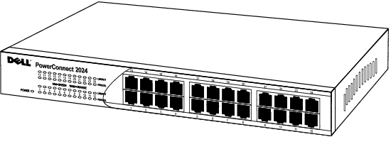
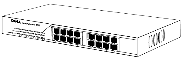
The PowerConnect 2016 and 2024 switches provide 16 and 24 10/100-Mbps ports respectively. With complete switching features like auto-sensing of line speed and auto-negotiation of duplex mode, the switches offer smooth network migrations and easy upgrades to network capacity.
These switches have the following features:
- Complies with IEEE 802.3 Type 10Base-T and IEEE 802.3 Type 100Base-TX
- 16 (PowerConnect 2016) or 24 (PowerConnect 2024) 10/100-Mbps switching ports
- Automatic negotiation for speed and duplex mode on all ports
- Backpressure flow control in half-duplex operation
- IEEE 802.3x PAUSE frame flow control in full-duplex operation
- Auto MDI/MDI-X
- 4-KB MAC address entries supported with hardware based aging
- Comprehensive LED indicator panel to monitor overall switching condition
- 19-inch rack-mountable
- Standard 1U chassis
- Internal power supply
Before you install a switch, please verify that your package contains the following items:
- Switch
- Self-adhesive rubber pads for desktop installation
- Rack mount kit for rack installation
- PowerConnect 2016 and 2024 User's Guide
- AC power cord
The LEDs on the front panel display the following information:
- Status of the power supply
- Connection speed of either 10-Mbps or 100-Mbps
- Data activity on the segment
- Full- or half-duplex operation mode
- Green — The unit is on and ready for use.
- Off — The unit is off.
- Green — 10-Mbps link pulses are detected.
- Blinking Green — A 10-Mbps connection is established and data is being transmitted or received on the port.
- Solid Orange — 100-Mbps IDLE symbols are detected.
- Blinking Orange — A 100-Mbps connection is established and data is being transmitted or received on the port.
- Off — No link is established.
- Orange — The port is operating at full-duplex mode.
- Off — No link established or the port is operating at half-duplex mode.
- Green — The unit is on and ready for use
- Off — The unit is off.
- Green — The port is operating at 100-Mbps.
- Off — The port is operating at 10-Mbps.
- Green — A link is established.
- Blinking Green — Data is being received or transmitted on this port.
- Off — No link is established.
- Green — The port is operating at full-duplex mode.
- Off — No link is established or the port is operating at half-duplex mode.
There are either 16 or 24 RJ-45 connectors on the front panel of the switch. The switches provide 10/100-Mbps switching ports that can sense the 10/100M speed and negotiate full or half-duplex mode automatically. These switching ports allow users to connect the switches to 10Base-T and 100Base-TX devices.
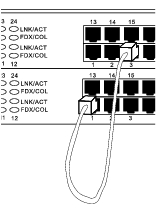
Each port supports Auto MDI & MDI-X functionality. When cascading with other switches or hubs, each port can connect directly to a switch or hub with straight through twisted pair cable.
By connecting a switch to desktop systems, you can form a small network. To improve network efficiency, use 100-Mbps full-duplex operation between the server and switch if the LAN adapter on the server can operate in full-duplex mode.
The switch is supplied with mounting brackets and screws for rack mounting, and rubber feet for stationing it on a flat surface.
The switch can be installed on any appropriate level surface that can safely support the weight of the hubs and their attached cables. There must be adequate space around the switch for ventilation and access cable connectors.
To install the switch on a flat surface, complete the following steps:
- Set the switch on the flat surface and check for proper ventilation.
Allow at least 2 inches (5.1 cm) on each side for proper ventilation and 5 inches (12.7 cm) at the back for power cord clearance.
- Attach rubber feet on each marked location on the bottom of the
chassis.
The rubber feet are optional but recommended to keep the unit from slipping.
The switch can be installed in most standard 19-inch racks.
 |
NOTE: For racks that
are not pre-threaded,
cage nuts are provided.
|
To install the switch in a rack, complete the following steps:
- Use the supplied screws to attach a mounting bracket to each side of
the switch.
- Position the switch in the rack and align the holes in the mounting
bracket with the holes in the rack.
- Insert and tighten two screws appropriate for your rack through each of
the mounting brackets.
|
Network Protocol and Standards Compatibility
|
| IEEE 802.3 CSMA/CD (ISO/IEC 8802-3) |
| IEEE 802.3 10Base-T (ISO/IEC 8802-3) |
| IEEE 802.3u 100Base-TX (ISO/IEC 8802-3) |
| IEEE 802.3x Flow Control (ISO/IEC 8802-3) |
|
Interface
|
| RJ-45 Connector |
| |
|
Power Supply
|
| 100-240VAC/50-60 Hz universal input |
|
Physical Dimensions
|
24 port | 341 x 230.5 x 43.2 mm (W x D x H)
13.43x9.07x1.70 inch |
16 port | 266 x 162 x 44 mm (W x D x H)
10.5 x 6.38 x 1.73 inch |
|
Environmental Specifications
|
Operating temperature | 0 to 40 |
Storage temperature | -20 to 70 |
Operating Humidity | 10 to 90% RH |
Storage Humidity | 10 to 95% RH |
Back to Contents Page