Back to Contents Page
Removing and Replacing Parts
Dell™ PowerVault™ 715N Systems Service Manual
The procedures in this section require that you remove the cover
and work inside the system. While working inside the system, do not attempt to
service the system except as explained in this manual and elsewhere in your
system documentation. Always follow the instructions closely. Make sure to review all
of the procedures in "Safety Instructions" in your System Information
document.
This section provides servicing procedures for components inside the system. Before you
start any of the procedures in this section, perform the following tasks:
When a replacement procedure is not provided, use the removal procedure in
reverse order to install the replacement part.
You need the following items to perform the procedures in this section:
- #0, #1, and #2 Phillips screwdrivers
- Wrist grounding strap
Removing the bezel provides access to the hard drives.
 |
CAUTION: See the
safety instructions in your System Information booklet before working inside your system. |
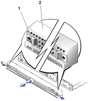
To remove the bezel, push the levers on the outside inward and pull the bezel
away from the system (see Figure 1).
Figure 1. Bezel Removal
To replace the bezel, push the levers inward and push the bezel onto the front
of the system.
The system has a cover that provides access to system board components and
the PCI expansion card. To service the system, remove the cover to gain access
to internal components.
 |
CAUTION: See the
safety instructions in your System Information booklet before working inside your system. |
- Push the latches on the top of the system inward (see Figure
2).
- Slide the system cover backward about 16 mm (0.6 inch) until the
embossed arrowheads on the sides of the cover and chassis are aligned (see Figure
2).
- Carefully lift the cover away from the system.
Figure 2. System Cover Removal
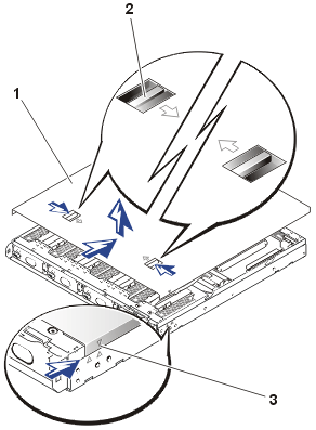 |
| 1 |
Cover |
| 2 |
Latches (2) |
| 3 |
Arrowheads aligned for removal |
|
- Ensure that tools, parts, or unconnected cables are not left inside the
system.
- Fit the cover over the sides of the chassis until the embossed rear
arrowhead is aligned with the arrowhead on the side of the cover (see Figure
2).
- Slide the cover forward
until the latches snap into place.
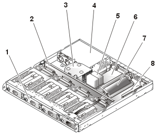
In Figure 3, the system cover and bezel are removed to provide an interior
view of the system.
Refer to this illustration to locate interior features and components discussed later in
this manual.
Figure 3. Inside the System
 |
| 1 |
Hard drives (4) |
| 2 |
Midplane board |
| 3 |
Cooling fan assembly |
| 4 |
Power supply |
| 5 |
Microprocessor and heat sink |
| 6 |
System board |
| 7 |
Memory modules (2) |
| 8 |
PCI riser card |
|
|
|
The system board holds the system's control circuitry and other
electronic components. Several hardware options such as the microprocessors and memory are
installed directly on the system board. The system board can
accommodate one PCI expansion card.
The hard-drive bays provide space for up to four, 1-inch hard drives. The hard drives are connected to an integrated
hard-drive controller on
the system board through a backplane board.
Power is supplied to
the backplane board, the system board, and internal peripherals through the
power supply. The backplane board provides power to
the hard drives.
During a service procedure, you might be required to change a jumper
or switch setting. For more information about the system board jumpers, see "Jumpers, Switches, and Connectors."
Your system comes with four IDE hard drives in a RAID configuration. The
drives are not hot swappable. Each hard drive is mounted in a hard-drive carrier.
 |
CAUTION: Read the safety instructions
in your System Information document. |
 |
CAUTION: Read the safety instructions
in your System Information document. |
- Shut down the system and disconnect the power cables from their outlets.
- Remove the bezel.
- Remove the power cord from the system power input
receptacle.
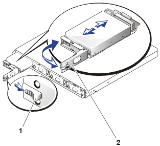
- Open the
drive carrier handle by pushing the release lever to the right (see Figure 4).
- Pull open the latch and use it to pull the drive carrier out of the drive
bay (see Figure 4).
Figure 4. Hard Drive and Carrier Removal
- Ensure that all configuration jumpers on the replacement drive are set to
the same settings as the drive you removed.
- If your replacement hard drive is installed in its carrier, open
the handle on the carrier.
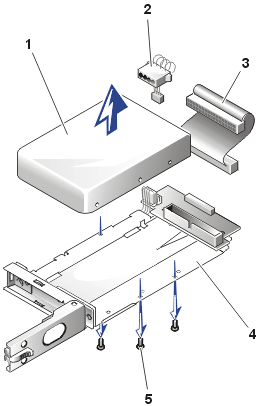
- If the replacement hard drive has no carrier, remove the faulty hard drive
from its carrier:
- Using a #1 Phillips screwdriver, remove
the screws that secure the drive to the carrier (see Figure
5).
- Remove the hard drive from the carrier.
Figure 5. Hard-Drive
Removal From Carrier
 |
| 1 |
Hard drive |
| 2 |
Power connector |
| 3 |
Interface cable |
| 4 |
Hard-drive carrier |
| 5 |
Screws (4) |
|
- Insert the replacement hard drive into the carrier
and install the screws you removed in step 2a to secure the drive.
 |
NOTICE: Ensure
that the hard drive's power cables do not extend beyond the outside (left)
edge of the carrier, which might cause damage to the wires. |
- Open the handle on the carrier and install the replacement hard drive and carrier
into its slot in the drive bay (see Figure
4).
- Close the handle until it engages the front panel, locking the drive in place.
- Replace the bezel.
- Run the system diagnostics
to test and prepare the new drive.
- Follow the appropriate procedure for restoring your data and adding
mirrors in the section, "Managing Hard Drives" in the System
Administrator's Guide.
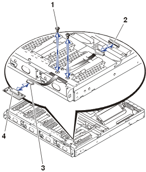
In Figure 6, the control panel is shown removed from the system chassis.
Figure 6. Control Panel Removal
 |
| 1 |
6-32 x 0.25-inch Phillips screw (3) |
| 2 |
Midplane connector (JP5) |
| 3 |
Ribbon cable connector |
| 4 |
Control panel board |
|
To remove the control panel assembly, perform the following steps.
 |
CAUTION: Read the safety instructions
in your System Information document. |
- Turn off the system.
- Remove the bezel.
- Disconnect the system power cables from their electrical outlets.
- Remove the system cover.
- Disconnect the ribbon cable from connector JP5 on the midplane board (see Figure
6).
- Using a #0 Phillips screwdriver, remove the two screws that secure the control panel to the
chassis.
- Push the ribbon cable forward until the control panel comes out of the front of the system chassis.
- Disconnect the ribbon cable from the control panel board.
A single fan assembly is mounted beside the microprocessor and heat-sink socket. This cooling fan directs cooling air across the microprocessor and heat
sink and across the memory modules and the PCI expansion card before exiting
the chassis through holes in the back panel.
 |
CAUTION: Read the safety instructions
in your System Information document. |
If you observe that a fan is not operating or if the server management application issues a fan-related error message, perform the following steps to replace the faulty
fan:
- Turn off the system.
- Remove the bezel.
- Disconnect the system power cables from their electrical outlets.
- Remove the system cover.
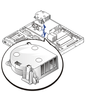
- Lift the fan assembly out of the chassis carefully, making sure that the
connector disconnects from the system board (see Figure
7).
Figure 7. Fan Assembly
When replacing the fan assembly, ensure that the fan fits over the pegs on
the chassis floor, as well as the fan power connector on the corner of the
system board.
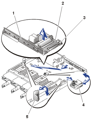
The system board and midplane board are joined together with a connector and secured to a metal bracket. Connectors on the front of the midplane
board connect to the four hard drives. On the back of the
midplane board is a single large connector that connects to the system board,
providing control and data signals and power for the four hard drives (see
Figure 8). A
ribbon cable from the midplane board connects to the control panel board.
 |
CAUTION: Read the safety instructions
in your System Information document. |
Figure 8. System Board and Midplane Board
Removal
 |
| 1 |
Midplane board |
| 2 |
System board |
| 3 |
Thumbscrew |
| 4 |
Center release latch |
| 5 |
Side latches (2) |
|
 |
CAUTION: Read the safety instructions
in your System Information document. |
- Turn off the system, including any attached peripherals, and disconnect the system from
its electrical outlet.
- Remove the bezel.
- Remove the system cover.
- Remove the fan assembly.
- Pull each hard-drive carrier partially out of its slot,
approximately 2.5 cm (1 inch).
- Label and disconnect the control panel ribbon cable attached to the
midplane
board (JP5).
- Disconnect the two DC power cables from their power
input connector on the system board.
- Remove all external peripheral cables from their connectors at the back of the system.
- Record the locations and remove all internal cables attached to
the system board.
- Remove the expansion card, if one is
installed.
- Remove the riser card.
- Release the side latches on each end of the midplane
board.
- Press the center release latch tab toward the midplane while pulling on
the latch's right edge.
The latch pivots away from the midplane board.
- Unscrew the thumbscrew securing the system board to the chassis floor.
- Slide the system board and midplane board toward the front of the system chassis about 6.3 mm
(0.25 inch).
- Carefully pivot the system board and midplane board up and out of the chassis.
Be sure to lift the midplane board first, and when it is free of the
chassis, pull the system board away from the back panel.
- Place the system board and midplane board on a smooth, antistatic surface.
- Remove the microprocessor.
- Remove the memory modules.
- Pivot the system board and midplane board assembly into
the chassis, first lowering the system board end, and then lowering the midplane
board. When the midplane board reaches the chassis floor, slide the assembly
to the rear about 6.3 mm (0.25 inch).
The grounding pins enter their holes on the
system board and the serial port connector protrudes from its opening
in the back panel.
- Tighten the thumbscrew to secure the system board to the chassis floor.
- Lock the side latches on each end of the midplane board.
- Pivot the center release latch tab toward the midplane until it locks in
place with a click.
- Install the memory modules.
- Install the microprocessor.
- Ensure that the system board jumpers and switches are set to the same settings as
the board you removed.
- Connect the two DC power cables to their power
input connectors (CN1 and CN2) on the system board.
- Install the riser card.
- Install the expansion card.
- Install the fan assembly.
- Replace the system cover.
- Replace the bezel.
- Reconnect any external peripheral cables that you disconnected from their connectors at the back of the system.
- Connect the power to the system and turn on the system.
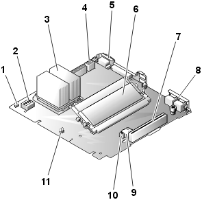
Figure 9 defines the system board features. The system board labels are in
parentheses. Refer to this figure when replacing your system
board or components that attach to the system board.
Figure 9. System Board Features
 |
| 1 |
Fan power connector (CPUFAN1) |
| 2 |
DIP switch (SW3) |
| 3 |
Microprocessor and heat sink (CPU) |
4 |
Power supply connectors (CN1 and CN2) |
| 5 |
Serial port connector (COM1) |
6 |
Memory modules (DIMM1 and DIMM2) |
7 |
PCI riser card slot (PCI1) |
8 |
LAN connectors (LAN1 and LAN2) |
| 9 |
Battery connector (BT1) |
| 10 |
Clear CMOS jumper (JP1) |
| 11 |
System version jumper (JP5) |
|
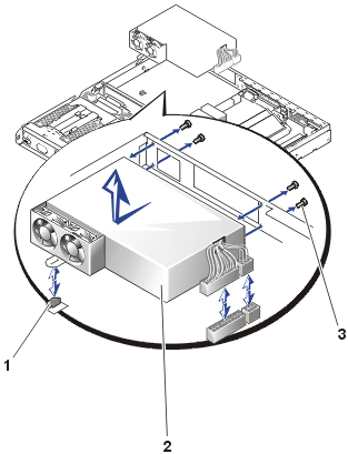
Your system has a single power supply, which is secured by a locking tab and four
screws (see Figure 10).
 |
CAUTION: Read the safety instructions
in your System Information document. |
Figure 10. Power Supply
Removal
 |
| 1 |
Locking tab |
| 2 |
Power supply |
| 3 |
Screws (4) |
|
To remove a power supply, perform the following steps.
 |
CAUTION: Avoid
touching the cable connectors on the power supply. Wait 10 to 20 seconds after
disconnecting the power cord before removing the power supply or coming into contact
with its cable connectors. |
- Turn off the system, including any attached peripherals, and disconnect the system from its electrical outlet.
- Open the bezel.
- Remove the system cover.
- Remove the fan assembly.
- Disconnect the two DC power connectors on the system
board (see Figure 9).
- Using a #1 Phillips screwdriver, remove the four Phillips screws securing the power supply
to the back of the system chassis.
- Push the power supply forward (and away from the back panel) about 6.3 mm
(0.25 inch).
The power supply must clear the locking tab on the floor of the chassis.
- Lift the power supply out of the chassis.
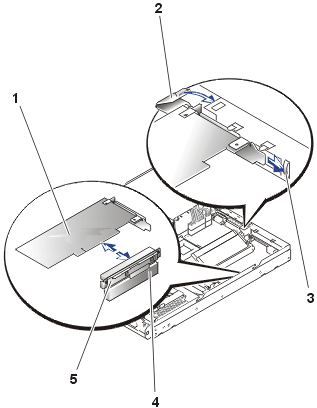
The system has a single PCI expansion-card socket that connects to the system
board through a riser card (see Figure 11).
 |
NOTICE: You can
only install low-profile PCI expansion cards in this system. |
 |
CAUTION: Read the safety instructions
in your System Information document. |
Figure 11. Expansion-Card
Replacement
 |
| 1 |
Expansion card |
| 2 |
Expansion-card latch |
| 3 |
Expansion-card bracket slot |
| 4 |
Riser-card slot |
| 5 |
Riser card |
|
 |
CAUTION: Read the safety instructions
in your System Information document. |
- Turn off the system, including any attached peripherals, and disconnect the system from
its electrical outlet.
- Remove the system cover.
- Release the expansion-card latch (see Figure
11).
- Remove any cables attached to the expansion card.
- Grasp the expansion card out and pull it away from the riser-card
connector.
Ensure that the expansion card's metal bracket is free of its slot.
- If you are removing the card permanently, install a metal filler bracket
over the empty card slot opening.
 |
NOTE: Installing a
filler bracket over an empty expansion slot is necessary to maintain
Federal Communications Commission (FCC) certification of the system. The
brackets also keep dust and dirt out of the system and aid in proper
cooling and airflow inside the system. |
- Replace the system cover.
- Reconnect the system and peripherals to the power source, and then turn on the
system.
To install a replacement or an additional expansion card, perform the following
steps:
- Prepare the replacement expansion card for installation.
See the documentation that came with the expansion card for information
about configuring the
card, making internal connections, or customizing the card for the
system.
- If the replacement card is an identical replacement, ensure that any
jumpers or configuration switches are set in an identical manner as the
expansion card you just removed.
- If not already installed, install the riser card.
 |
NOTICE: The riser
card must be properly seated in its system board connector before
attempting to install an expansion card. |
- Insert the expansion card's card-edge connector firmly into the riser
card, and ensure that the mounting bracket enters its slot on the chassis
back panel (see Figure 11).
- When the card is fully seated in the connector and the card-mounting
bracket is in its slot, close the
expansion-card latch.
- Connect any cables that should be attached to the card.
See the documentation that came with the card for information about cable connections.
- Replace the system cover.
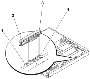
The riser card supports a single PCI expansion card and connects to the riser-card
slot on the system board and the side of the system chassis (see
Figure 12).
 |
CAUTION: Read the safety instructions
in your System Information document. |
- Turn off the system, including any attached peripherals, and disconnect the system from
its electrical outlet.
- Remove the system cover.
- Remove the expansion card.
- Grasp the riser card on each end and lift it out of its slot on the system
board. Use care to lift it out evenly so that the metal tabs easily leave
their slots on the chassis wall (see Figure 12).
Figure 12. Riser Card Removal
 |
| 1 |
Riser-card slot |
| 2 |
Riser card |
| 3 |
Tabs |
| 4 |
Slots on chassis |
|
 |
NOTICE: The riser
card must be properly seated in its system board connector before
attempting to install an expansion card. |
When installing a replacement riser card, align the tabs on the back of
the riser card with the mating slots on the wall of the system chassis. When properly
aligned, the card-edge connector should be properly positioned. Firmly press the
riser card into its system board connector.
The two memory module sockets on the system board can accommodate from 256 MB to 1 GB of registered SDRAM. Memory modules installed in the sockets must be
PC-133 compliant.
 |
CAUTION: Read the safety instructions
in your System Information document. |
System Memory Upgrade Kits
You can upgrade the system memory by installing combinations of 256- or
512-MB registered memory modules. If you receive an error message
stating that the maximum memory has been exceeded, see "Codes,
Error Messages, and Indicators." You can purchase memory upgrade kits as needed.
 |
NOTE: The memory modules must be
PC-133 compliant. |
Memory Module Installation Guidelines
 |
NOTE: Parts of
this procedure require you to use the console redirection function on the
serial port. See your System Administrator's Guide for information about
connecting to the system through console redirection. |
Table 1 illustrates two sample memory configurations based on
these guidelines.
Table 1. Sample DIMM Configurations
Desired
Memory |
DIMM1 |
DIMM2 |
| 256 MB |
256 MB |
Open |
| 512 MB |
512 MB |
Open |
 |
CAUTION: Before
you perform this procedure, you must turn off the system and disconnect it
from its power source. For more information, see the safety instructions
in your System Information document. |
 |
CAUTION: See
"Protecting Against Electrostatic Discharge" in the safety instructions
in your System Information document. |
- Turn off the system, including any attached peripherals, and disconnect
the system from the electrical outlet.
- Remove the cover.
- Locate the memory module sockets in which you want to install or replace
memory module pairs.
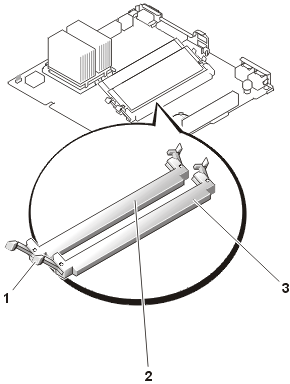
Figure 13 shows the location of the memory module sockets.
Figure 13. Memory Module Socket Locations
 |
| 1 |
Extractor lever |
| 2 |
DIMM2 |
| 3 |
DIMM1 |
|
- Install or replace the memory module(s) as necessary to reach the
memory total you want (see "Installing Memory Modules" or "Removing
Memory Modules").
- Replace the system cover.
- Reconnect the system to the electrical outlet, and then turn on the system.
 |
NOTE: To perform the next step, you
must
use the console redirection function on the serial port (COM1). See the System
Administrator's Guide for more information about console redirection. |
- (Optional) Press <F2> to enter the BIOS Setup
utility, and then check the
Extd Memory setting on the Standard CMOS Setup screen.
 |
NOTE: If you use a
version of Windows 2000 earlier than Service Pack 2, the function keys do
not work. You must press <Esc><2>. |
The
system should have already changed the value in the Extd Memory
setting to reflect the newly installed memory.
- If the Extd Memory value is incorrect, one or more of the memory
modules might not be installed properly. Repeat steps 2–5,
ensuring that the memory modules are firmly seated in their
sockets.
- Run the system memory test in the system diagnostics.
- Replace the system cover.
 |
CAUTION: Before
you perform this procedure, you must turn off the system and disconnect it
from its power source. For more information, see the safety instructions
in your System Information document. |
 |
CAUTION: See
"Protecting Against Electrostatic Discharge" in the safety instructions
in your System Information document. |
To install a memory module, perform the following steps.
 |
CAUTION: Read the safety instructions
in your System Information document. |
- Turn off the system, including any attached peripherals, and disconnect the
power cord from the electrical outlet.
- Remove the system cover.
- Locate the memory module sockets in which you want to install a memory
module.
Figure 13 shows
the location of the memory module sockets.
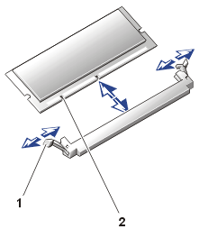
- Press down and outward on the ejectors on the memory module socket, as shown in Figure
14,
to allow the memory module to be inserted into the socket.
Figure 14. Adding or Removing a Memory Module
 |
| 1 |
Memory module socket ejectors (2) |
| 2 |
Memory module |
|
|
|
- Align the memory module's edge connector with the
alignment keys of the memory module socket, and then insert the memory module in the socket.
The memory module socket has two alignment keys that allow the memory module
to be installed in the socket
in only one way.
- Press down on the memory module with your thumbs while pulling up on the
ejectors with your index fingers to lock the memory module into the socket (see Figure 14).
- When the memory module is properly seated in the
socket, the ejectors on the memory module socket align with the ejectors on the other
sockets with memory modules installed.
- Repeat steps 4–7 to install the remaining memory modules.
- Perform steps 5–10 of the procedure, "Performing
a Memory Upgrade."
 |
CAUTION: Before
you perform this procedure, you must turn off the system and disconnect it
from its power source. For more information, see the safety instructions
in your System Information document. |
 |
CAUTION: See
"Protecting Against Electrostatic Discharge" in the safety instructions
in your System Information document. |
- Turn off the system, including any attached peripherals, and disconnect the
power cord from its power source.
- Remove the system cover.
- Locate the memory module sockets in which you want to remove a memory module.
Figure 13 shows
the location of the memory module sockets.
- Press down and outward on the ejectors on each end of the socket
until the memory module pops out of the socket (see Figure 14).
To take advantage of future options in speed and functionality, you can
replace the microprocessor.
Each microprocessor and its associated Level 2 cache are contained in a pin grid
array (PGA)
package that is installed in a ZIF socket on the system board. The following
subsection describes how to install or remove the microprocessor.
To replace the microprocessor, perform the following steps.
 |
NOTE: Only a technically knowledgeable person should perform
this procedure. |
 |
CAUTION: See
"Protecting Against Electrostatic Discharge" in the safety instructions
in your System Information document. |
 |
CAUTION: The
microprocessor and heat-sink assembly can get extremely hot during system operation. Be
sure the assembly has had sufficient time to cool before you touch it. |
 |
CAUTION: When
handling the microprocessor and heat-sink assembly, take care to avoid sharp edges on the
heat sink. |
- Turn off the system, including any attached peripherals, and disconnect the
power cord from the electrical outlet.
- Remove the system cover.
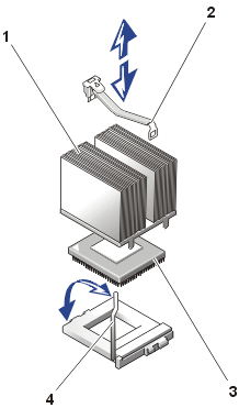
- Press down on the
heat- sink securing clip to release it from the retaining tab on the
ZIF socket (see Figure 15).
- Remove the securing clip.
- Carefully remove the heat sink and set it down with the underside of the heat sink
facing up.
 |
CAUTION: Ensure
that the thermal pad on the underside of the heat sink is not damaged
during handling. |
 |
NOTE: Observe the orientation of the heat sink with respect to the
microprocessor and its ZIF socket.
|
- Pull the socket release lever straight up until the microprocessor is
released (see Figure 15).
Figure 15. Microprocessor and Heat-Sink
Replacement
 |
| 1 |
Heat-sink assembly |
| 2 |
Securing clip |
| 3 |
Microprocessor |
| 4 |
ZIF socket release lever |
|
- Lift the microprocessor away from the ZIF socket and leave the release
lever in the upright position so that the socket is ready for the
replacement microprocessor (see Figure 15).
 |
NOTICE: Be careful
not to bend any of the pins when removing the microprocessor. Bending
the pins can permanently damage the microprocessor. |
- Unpack the new microprocessor.
If any of the pins on the microprocessor appear bent, contact technical
support.
- Identify the pin-1 corner of the microprocessor by locating the tiny gold
triangle that extends from one corner of the large central rectangular area.
The gold triangle points toward pin 1, which is also uniquely
identified by a square pad.
 |
NOTE: Identifying
the pin-1 corner is critical to positioning the microprocessor correctly. |
- Align the pin-1 corner of the microprocessor with the pin-1 corner of the
microprocessor socket.
- Install the microprocessor in the socket (see Figure
15).
 |
NOTICE: Positioning
the microprocessor incorrectly can permanently damage the microprocessor and
the system when you turn on the system. When placing the microprocessor in
the socket, be sure that all of the pins on the microprocessor enter the
corresponding holes. Be careful not to bend the pins. |
If the release lever on the microprocessor socket is not positioned all the
way up, move it to that position.
With the pin-1 corners of the microprocessor and socket aligned, set the
microprocessor lightly in the socket and make sure all pins are matched with the
correct holes in the socket. Because the system uses a ZIF microprocessor
socket, do not use force, which could bend the pins if the microprocessor is
misaligned. When the microprocessor is positioned correctly, it drops down
into the socket with minimal pressure.
When the microprocessor is fully seated in the socket, rotate the socket
release lever back down until it snaps into place, securing the microprocessor.
- Place the heat sink you removed in step 5 on top of the microprocessor (see Figure 15).
 |
CAUTION: Ensure
that the thermal pad on the underside of the heat sink is not damaged
during handling. |
- Orient the securing clip as shown in Figure 15.
- Hook the end of the clip without the heat-sink latch to the tab on the edge
of the socket.
- Push down and pivot the heat-sink latch until the hole on the clip latches
onto the ZIF socket tab.
Make sure that the latches engage.
Replace the system cover.
- Reconnect the system and peripherals to the power source, and then turn on the
system.
 |
NOTE: To perform the next step, you
must use the console redirection function on the serial port (COM1). See the System
Administrator's Guide for more information about console redirection. |
From console redirection, check to see that the presence of the new processor
is listed during the POST. As the system boots, it detects the presence of the
new processor and automatically changes the system configuration information in the BIOS Setup
utility.
- Run the system diagnostics to verify that the new microprocessor operates
correctly.
See "Running the System
Diagnostics" for information about
running the system diagnostics and troubleshooting any problems that might occur.
 |
NOTE: Parts of
this procedure require you to use the console redirection function on the
serial port (COM1). See your System Administrator's Guide for information about
connecting to the system through console redirection. |
The system battery maintains system configuration, date,
and time information in a special section of memory when you turn off the system. The
operating life of the battery ranges from 2 to 5 years, depending on how you use the
system (for example, if you keep the system on most of the time, the battery gets little
use and, thus, lasts longer).
You might need to replace the battery if an incorrect time or
date displays during the boot routine, along with a message about wrong
time, invalid configuration information, or bad CMOS checksum.
 |
NOTE: To perform this procedure, you
must use the console redirection function on the serial port (COM1). See the System
Administrator's Guide for more information about console redirection. |
To determine if the battery needs replacing, perform the following steps:
- Re-enter the time and date through the BIOS Setup
utility.
- Turn off and disconnect the system from the electrical outlet for a few
hours.
- Reconnect and turn the system on again.
- Enter the BIOS Setup utility.
If the date and time are not correct in the BIOS Setup utility, replace the
battery.
 |
NOTES: Some software
might
cause the system time to speed up or slow down. If the system seems to operate normally
except for the time kept in the BIOS Setup utility, the problem might be caused by
software rather than by a defective battery. If the system is turned off for long periods of time (for weeks or months), the NVRAM may lose its system configuration information. This situation is not caused by a defective battery. |
You can operate the system without a battery; however, the system configuration
information maintained by the battery in NVRAM is erased each time you shut down the
system. Therefore, you must re-enter the system configuration information and reset the
options each time the system initializes, until you replace the battery. The battery is a 3.0-volt (V), coin-cell CR2032-type
battery.
To remove the battery, perform the following steps.
 |
CAUTION: Before you perform this procedure, you must turn off the system and disconnect it
from its power sources. For more information, see the safety precautions in your
System Information document. |
 |
CAUTION: There is a danger of a new battery
exploding if it is incorrectly installed. Replace the battery only with the same or
equivalent type recommended by the manufacturer. Discard used batteries according to the
manufacturer’s instructions. |
- Enter the BIOS Setup utility and, if possible, make a printed copy of the
BIOS Setup
screens.
See "Using the BIOS Setup Utility."
- Shut down the system, including any attached peripherals, and disconnect the system from the electrical outlet.
 |
CAUTION: Read the safety instructions
in your System Information document. |
- Remove the system
cover.
- Remove the battery (see Figure 9 for the battery location).
Pull the tab back on the battery socket and remove the battery from its
socket with your fingers.
- Pull the tab back on the battery socket and install the new battery with the side labeled "+"
facing up (see Figure 16).
Figure 16. Battery Replacement
- Replace the system cover.
- Reconnect the system to the electrical outlet, and then turn on the system power.
- Enter the BIOS Setup utility to confirm that the battery
operates properly.
- Enter the correct time and date through the BIOS Setup utility's Standard
CMOS Setup
settings.
Also, re-enter any system configuration information that is no longer displayed on
the BIOS Setup screens, and then exit the BIOS Setup utility.
- To test the newly installed battery, shut down and
disconnect the system from the electrical source for at least an hour.
- After an hour, connect the system to an electrical
source and turn on the power.
- Enter the BIOS Setup utility and if the time and date are still incorrect,
replace the system board.
Back to Contents Page
