Back to Contents Page
Setting Up the Rack: Dell® PowerEdge® Rack-Mountable Solutions Installation Guide
Before You Begin | Safety Information | Recommended Tools | Setting up the Rack | Removing the Rack From the Pallet | Positioning the Rack | Removing the Doors From the Rack | Installing a Rack Coupling Kit | Installing the Stabilizer Feet | Installing or Removing a Side Panel | Removing a Cable Access Plate
Before setting up the rack, review the site requirements outlined in the Rack Configuration Guide, and complete any necessary preparations.
Carefully read the following safety information before you begin setting up the rack.

|
WARNING: Installing components in the rack without the front and side stabilizer feet installed could allow the rack to tip over and cause bodily injury under certain circumstances. Always install the stabilizer feet before installing components in the rack. |
The stabilizer feet help prevent the possibility of the rack tipping over when a component is installed and then pulled out of the rack to the fully extended position of the slide assemblies. For instructions on installing the stabilizer feet, refer to Installing the Stabilizer Feet.
To set up the rack, you should have the following tools:
- A pallet jack or forklift to move the rack pallet
- Large and medium-sized Phillips screwdrivers
You must perform the following tasks to set up the rack:
- Remove the rack from the pallet.
- Position the rack.
- Remove the doors.
- If you are setting up multiple racks, install an optional coupling kit.
- Install the stabilizer feet.
- If you are setting up a stand-alone rack, remove the side panels.
- Remove a cable access plate.
The sections that follow include instructions for performing these tasks.
Use the following procedure to remove the rack from the pallet.

|
WARNING: To prevent personal injury due to the size and weight of the rack, have at least two people move the rack. |
- Remove the top section from the packaging.
The top section is secured by plastic clips.
- Remove the two side pieces of the packaging.
Remove the Phillips screws from the boards at the base of the side pieces.
- Remove the two ramps and the package of Phillips screws stored between the rack's casters.
- Attach the ramps to the pallet using four Phillips screws (see Figure 1, Removing the Rack From the Pallet).
- Remove the two bolts securing each side of the rack to the pallet.
- With one or two people supporting the front of the rack and one person behind the rack, carefully roll the rack down the ramp and off of the pallet.
Figure 1. Removing the Rack From the Pallet

|
1 |
screws (4) |
|
2 |
bolts (4) |
|
3 |
ramps (2) |
When positioning the rack, allow the following minimum clearances:
- For operation, leave at least 46 cm (1.5 ft) of clearance in front of the rack and 31 cm (1 ft) behind the rack to allow adequate airflow.
- For servicing, allow 61 cm (2 ft) of space behind the rack and 165 cm (65 inches) in front of the rack.
Before installing the equipment in the rack, you may wish to remove the doors from the rack to improve access to the interior of the rack and to prevent damage to the doors. Use the following procedure to remove the doors.

|
WARNING: To prevent personal injury due to the size and weight of the doors, never attempt to remove or replace the doors by yourself. |
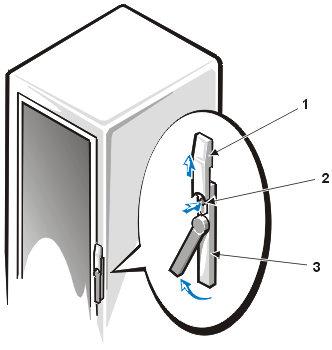
- Open the latch on the front door.
Slide the latch's push button cover up as far as it will go, press the push
button, rotate the handle clockwise until the latch releases, and then pull the door open (see Figure 2, Opening the Latch on the Door).
Figure 2. Opening the Latch on the Door
|
1 |
push button cover |
|
2 |
push button |
|
3 |
handle
|
- Remove the front door as shown in Figure 3, Removing the Doors.
- One person should grasp the top of the door to stabilize it. The other person should grasp the bottom of the door.
- The person holding the bottom of the door should press the release lever on the bottom hinge and then pull the bottom of the door away from the rack a few inches.
- The person holding the top of the door should press the release lever on the top hinge and then pull the door away from the rack.
- Store the door in an area where it cannot fall and hurt someone while you install the equipment in the rack.
Figure 3. Removing the Doors

- Repeat steps 1 and 2 to remove the back door.
If you are setting up a suite of racks, you should install a coupling kit between adjacent racks. Follow these steps to install a coupling kit:
- Position the two racks side by side.
- Install the four L-brackets (see Figure 4, Installing the L-Brackets).
The four brackets fit in the lower and upper corners of the rack's vertical rails. Secure each bracket to the vertical rails of the two racks using six 5.5 x 13-mm Phillips self-tapping screws.
Figure 4. Installing the L-Brackets

|
1 |
5.5 x 13-mm screws (24) |
|
2 |
coupling brackets (4) |
|
3 |
vertical rail
|
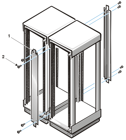
- Install the two coupling brackets using four 5.5 x 13-mm Phillips self-tapping screws per bracket (see Figure 5, Installing the Coupling Brackets).
Figure 5. Installing the Coupling Brackets
|
1 |
coupling brackets (2) |
|
2 |
5.5 x 13-mm screws (8) |
For safety reasons, you should install stabilizer feet on the rack, as follows:
- Install front and side feet on a stand-alone rack.
- Install front feet on all racks in a suite, as well as a left or right foot on the end racks in the suite.
Follow these steps to install a stabilizer foot:
- Extend the round levelling foot at each corner of the rack.
Turn each foot clockwise until it contacts the floor, then lock the foot in place by tightening the locknut counterclockwise.
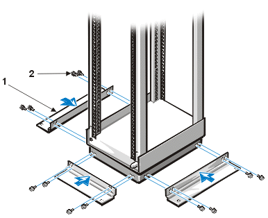
- Position the stabilizer foot against the rack such that the mounting holes in the foot are aligned with the corresponding holes in the rack (see Figure 6, Installing the Stabilizer Feet).
- Install the four hex-head screws to secure the foot to the rack.
Figure 6. Installing the Stabilizer Feet
|
1 |
stabilizer feet (3) |
|
2 |
screws (4 per foot) |
You may need to remove a side panel from a rack to gain access to the rack's interior or to transfer the panel to another rack in a suite of racks. Follow these steps to remove a side panel from the rack.

|
WARNING: To prevent personal injury due to the size and weight of the side panel, never attempt to remove or replace the side panels by yourself. |
- Remove or open the front door of the rack.
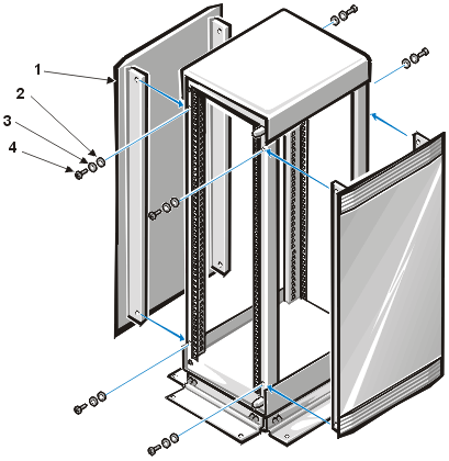
- Remove the two screws and washers securing the front edge of the side panel to the rack (see Figure 7, Removing the Side Panels).
Figure 7. Removing the Side Panels
|
1 |
side panels (2) |
|
2 |
serrated washers (4 per panel) |
|
3 |
washers (4 per panel) |
|
4 |
screws (4 per panel; 2 per edge)
|
- Open or remove the back door.
- While one person supports the side panel, remove the remaining two screws securing the side panel to the rack.
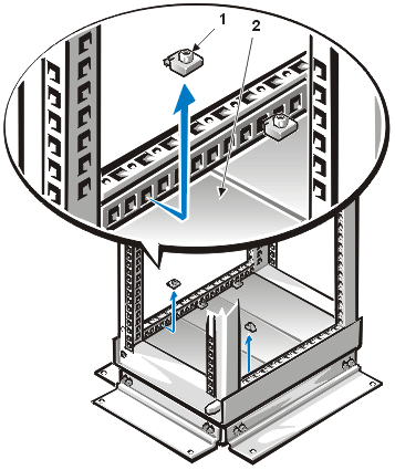
Before installing equipment in the rack, you should remove one of the cable access plates in the bottom of the rack to allow power cables to exit the rack. Follow these instructions to remove the cable access plate:
- Loosen the two hold-down screws securing the plate, and remove them from the rack (see Figure 8, Removing the Cable Access Plate).
Figure 8. Removing the Cable Access Plate
|
1 |
hold-down screws (2) |
|
2 |
cable access plate
|
- Reach underneath the rack and lift the plate from the rack.
You may need to strike the plate firmly to dislodge the plate.
Back to Contents Page


