F. E. C. O.
|
FECO:
|
COMMS#76-1 RouterBOARD ViBE
|
|
PRODUCT:
|
MikroTik
RouterBOARD
|
|
PRODUCT WEB SITE:
|
http://www.voipex.co.uk/
|
|
RELEASE DATE:
|
30 November
2018
|
|
ESTIMATED MAN HOURS:
|
0.5 hours
|
|
CLASS OF CHANGE:
|
N/A
|
|
REASON FOR CHANGE:
|
New product superseding P2PB-203
|
|
RELATED FECO/AB:
|
N/A
|
Configuration of the MikroTik RouterBOARD as ViBE
1. Note 1
2.
Introduction 1
3.
Specifications 2
4.
Prerequisites 2
5. Hardware
Configuration 2
6. Setting IP
Addresses 3
7. Set up the
ViBE tunnel 4
8. Using the
ViBE box for dhcp 7
9. Using the
ViBE box for wireless 7
10.
Defaulting the ViBE box 8
11. Example
ViBE Configuration Document 9
1. Note
1.1 Throughout
this document a carriage return is shown either by the symbol ¿ or <CR>, a SPACE in a string is shown by the symbol Ñ all other spaces are purely cosmetic.
A tab is shown as <Tab>, Function keys as <F10> and
control as <Ctrl>
2. Introduction
2.1 The
Voipex ViBE box P2PB-203 is superseded by the MikroTik RouterBOARD
EDP have been using Voipex
P2BB-203 to make use of 2 ADSL connections for resilience.
We will now use this device for
the same purpose
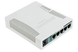
This is very different inasmuch as
it has 5 ports which can be configured in many ways, and it is a completely
different design
Also, there are no external LEDs
to see if the tunnel is established, see images below
Previous unit, black,
silver or red New
unit
3. Specifications
The
RB951G-2HnD is a wireless SOHO Gigabit AP with a new generation Atheros CPU and
more processing power. It has five Gigabit Ethernet ports, one USB 2.0 port and
a high power 2.4GHz 1000mW 802.11b/g/n wireless AP with antennas built in
It has the same form factor and price as the previous model
(RB751G-2HnD). But it has a 600Mhz CPU (400Mhz) and 128MB of RAM (64MB)
4. Prerequisites
Laptop (or PC) and a
CAT5 cable
LAN IP Address and subnet including DHCP range if required
WAN IP Address for first line
WAN IP Address for second line
Wireless settings if necessary
Access to both ADSL routers, login, password, IP Addresses
5. Hardware Configuration
5.1 Connect a CAT5 cable to port2 as dhcp
Browse
to the RouterBOARD on 192.168.3.1 and Login with admin, password
This will take you to the system Information screen: -
5.2 Note the MAC Address as this will
be used in the config form (example in section 11)
5.3 From the System tab, go to Settings
and enter the Host Name as appropriate
5.4 Check
the current time, if it is out set it under NTP Servers, in the Set
Time Manually field
Select Save Changes
5.5 Staying in the System tab, go to Password
Set a password
Select Save Changes and Apply Changes
The same password is used for ssh access, login as root
using the password set above
6. Setting IP Addresses
Select the Network tab
There will only be the following Network Interfaces
lan port2
none
wan port1
Management port5
We will be deleting Management and using it as wan2
6.1 From the Networks tab select Networks
Select Edit to the right of Management and at the
bottom, click Remove Network Management
Select Save Changes to the right hand side
6.2 Add a Network
for wan2 as follows
Type wan2 in the Add Network box, then select Add
Network
This will then take you to the Network Configuration
for wan2
Connection Type Static
IP
Type None
IP Address Set
as required
Netmask Set as required
Default Gateway Set
as required (This can only
be on one interface, choose the better connection)
Select Save Changes to the right hand side
6.3 Back at Interfaces, there will now
be three Networks shown; lan, wan & wan2
Using the drop down, allocate port5
to wan2
Select Save Changes and Apply
Changes to the right hand side
6.4 Select the Network tab, then Networks
Edit the lan network: -
Set the Connection Type to
Static IP and enter the IP Address
and subnet mask
Select Save Changes
6.5 Edit the wan network: -
Set the Connection Type to Static IP and enter the IP Address and subnet mask
Select Save Changes and Apply Changes
7. Set up the ViBE tunnel
There are four elements to this
1. Adding
forwarding rules to routers
2. Editing
/etc/vibe.conf
3. Adding
routes
4. Editing
/etc/init.d/tables to set up SNAT/DNAT
7.1 Amend each router firewall to forward UDP
65500 to the ViBE unit
Router Firewall Example: -
7.3 Select the ViBE tab, then Configuration
Copy the highlighted text below
into the /etc/vibe.conf box, edit the IP’s and remove the networks/lines as
necessary, e.g: –
remote 0.0.0.0
{ (start of section)
name =
“Customername_ViBE_Server”
provision_server =
10.88.89.241 (depends on whether it is
an EDP ADSL & which ViBE at MK)
symmetric = yes
network 10.1.2.21/32
{} (a server at MK)
network 10.1.5.25/32 {} (a second server at MK)
network 91.209.246.4/32 {} (server
to allow printing to 10.1.1 subnet)
network 91.209.246.131/32 {}
(server to allow printing to 10.1.2
subnet)
network 91.209.246.126/32 {} (server
to allow printing to 10.1.3 subnet)
network 91.209.246.236/32 {} (server
to allow printing to 10.1.4 subnet)
network 91.209.246.3/32 {} (server to allow printing to 10.1.5
subnet)
source_address =
10.193.85.253 (the interface
connected to the adsl see ‘wan’ above)
} (end of section)
remote 91.209.246.241
{ (start of section)
provision_server =
91.209.246.241 (assumes other provider on
ViBE 1, .242 for ViBE 2 at MK)
symmetric = yes
source_address =
192.168.55.253 (the interface
connected to the adsl see ‘wan2’ above)
parent = 0.0.0.0 (to go back to top of file)
} (end of section)
Select Save Changes and Apply
Changes
7.4 Go
to Network, Routes
Add into Configured IPv4 Static Routes
Example
Destination Gateway Netmask Metric Use
with Name
10.88.89.241 10.193.85.254 255.255.255.255 10 wan edp
(The EDP ADSL leg)
91.209.246.241 192.168.55.1 255.255.255.255 10 wan1 other
(The other provider ADSL leg)
192.168.96.211 10.193.85.254 255.255.255.255 10 wan support
(To allow browser access from MK even if the default gateway is
other provider)
The Destination numbers
depend on the contents of the /etc/vibe/conf file under Provision
Server
The Gateways
depend on the interfaces being used, it is the router
on the ViBE interface
The Netmask
is always 255.255.255.255 for the Provision Server
The Metric is
always 10
Use with applies to the name of the relevant
Interface under Network Configuration
Select Apply
Changes
If successful you
will see both tunnels up in the ViBE, Status page
If it is not
successful, one of the entries will be in red
Check: -
·
IP
Addresses of Interfaces, including Subnet masks
·
vibe.conf
·
Static Routes
·
That the
corresponding router is on line with corresponding UDP 65500 rules in place
7.5 Edit iptables to
allow access out to the Internet via the Default Gateway or in
using DNAT
ssh
to the ViBE as root on the corresponding interface to which you are connected
E.g. ssh Ñ root@10.193.85.253 ¿
Log in and list the interfaces and
note the interface names being used for each IP: -
# ifconfig
¿
Edit the tables file: -
# cd Ñ /etc/init.d ¿
# vi Ñ tables ¿
Insert the following lines using the interface names and IP’s as
shown in ifconfig: -
iptables -F
iptables -t nat -F
iptables -t nat -A POSTROUTING -o eth0.2 -j SNAT –to-source 10.193.85.253
#iptables -t nat -A POSTROUTING -o eth0.1 -j SNAT –to-source 192.168.55.253
iptables -t nat -L
Write away the file to save the changes: -
:wq! ¿
The interface used for SNAT
is the one that has the Default Gateway, hash/unhash as applicable
# chmod Ñ 755 Ñ tables ¿
Create a symbolic link in the rc.d
directory so that tables runs at startup:
-
# cd Ñ /etc/rc.d ¿
# ln Ñ -s Ñ ../init.d/tables Ñ S99tables ¿
Run
the tables: -
# sh Ñ S99tables ¿
List the live current rules to check: -
# iptables Ñ
-t Ñ nat Ñ -L ¿
8. Using the ViBE box for dhcp
If DHCP is required on the LAN, the vibe can be configured
to do this: -
Go to Network, DHCP
Select lan DHCP On
Enter the Start Last Octet and the Number of IPs
At the first Option dropdown
Select DNS Servers (6) and enter the IP’s as 8.8.8.8,1.1.1.1
At the second Option dropdown
Select Routers (3) and enter the IP of the Default
Gateway to publish to the dhcp Clients
(I.E. the ViBE LAN port ). E.g. 192.168.3.1
Select
Save Changes and Apply Changes to the right hand side
If static routes need to be
published
You need to add the DHCP service
" Classless Static Routes"
This option does not exist
initially. You need to add
it using a custom setting. So
create the file:-
# vi /etc/custom/dhcp_options
In this file add the line
121:Classless Static Route (121)
Then restart networking or reboot.
You will now see the new option in
the drop down menu.
– – –
You can set this in
Networks->DHCP
then select the service
"Classless Static Route (121)
in the Options Menu.
The way that routes are added is
using Hex values for
subnet mask, destination IP and
next hop router.
So for a static route to 8.8.8.8 /
32 host via 192.168.2.77
this will need to be translated to
the hex equivalent, eg:-
subnet Dest
IP Gateway
/32 8.8.8.8 192.168.2.77
Hex :
20 08.08.08.08 c0.a8.02.4d
The format for this is
20:08:08:08:08 :c0:a8:02:4d
To do the hex conversion, you can
use printf on the server/cpe command line
to convert from hex to dec and dec
to hex like so:
printf "%x\n" 192
c0
printf "%d\n" 0xc0
192
When you connect your host to the
vibe device and it requests the DHCP
info the routing table should
show. :-
Destination Gateway Genmask Flags Metric Ref Use Iface
0.0.0.0 192.168.2.77 0.0.0.0 UG
0 0 0 eth0
8.8.8.8 192.168.2.77 255.255.255.255 UGH
0 0 0 eth0
192.168.2.64 0.0.0.0 255.255.255.240 U 1
0
0 eth0
(Note: In this example host gets
an IP address of 192.168.2.71)
Also note that the subnet mask is
the first parameter to be checked.
It will only take into account the
following bytes for what is appropriate
for that subnet mask.
So for a /32 subnet mask it needs
all four bytes of the destination address.
For a /8 network it only looks at
the following single byte. Then what follows that must
be the next hop ip.
So for a static route of 10.0.0.0/
8 via 192.168.2.77 you will need
subnet network destination IP
08: 0a: c0:a8:02:4d
so its :-
08:0a:c0:a8:02:4d
This will give you :-
Kernel IP routing table
Destination Gateway Genmask Flags Metric Ref Use
Iface
0.0.0.0 192.168.2.77 0.0.0.0 UG 0
0 0
eth0
10.0.0.0 192.168.2.77 255.0.0.0 UG 0
0 0
eth0
If you try and use :-
08: 0a:00:00:00: c0:a8:02:4d
/8 10.0.0.0 192.168.2.77
It will be interpreted as :-
08: 0a: 00:00:00:c0 :a8:02:4d
/8 10.0.0.0 0.0.0.192 ignored
You will get:-
Destination Gateway Genmask Flags Metric Ref Use Iface
0.0.0.0 192.168.2.77 0.0.0.0 UG 0
0 0
eth0
0.0.0.192 0.0.0.0 255.255.255.255
UH 0
0 0
eth0 <- wrong
10.0.0.0 0.0.0.192 255.0.0.0 UG 0
0 0
eth0 <- wrong
You can append static routes
together using a colon. EG:-
20:08:08:08:08 :c0:a8:02:4d :08 :0a
:c0:a8:02:4d
Will give you :-
Destination Gateway Genmask Flags Metric Ref Use Iface
0.0.0.0 192.168.2.77 0.0.0.0 UG 0
0 0
eth0
8.8.8.8 192.168.2.77 255.255.255.255
UGH 0
0 0
eth0
10.0.0.0 192.168.2.77 255.0.0.0 UG 0
0 0
eth0
192.168.2.64 0.0.0.0 255.255.255.240 U 1
0 0
eth0
– --- --- ---
Example from Fielden Factors
You can only add 32 bit subnet
mask, 29 bit does not work to Windows PCs, so add each server separately
Subnet Mask Destination Gateway
32 10.1.4.9 10.192.32.254 Quantum LIVE
20: 0a:01:04:09:0a:c1:20:fe
32 10.1.4.11 10.192.32.254 Quantum TEST
20: 0a:01:04:0b:0a:c1:20:fe
9. Using the ViBE box for wireless
9.1 If wireless is required then the LAN interface needs to
be set to Bridged first
From the Networks tab select Networks
Edit lan
Set Type to Bridged
Select Save Changes and Apply
Changes to the right hand side
9.2 Go to Wireless
Under Wireless
Adapter radio0 Configuration: -
Country Code UNITED KINGDOM
Radio On
Under Wireless Virtual
Adaptor Configuration for Wireless Card radio0: -
Network lan
Mode Access
Point
ESSID Set
as required
Encryption Type WPA+WPA2(PSK)
WPA PSK as
required
Select Save Changes and Apply
Changes to the right hand side
Note you do not see any indication
on the MikroTik RouterBOARD to show if wireless is on
10. Defaulting
the ViBE box
10.1 With the MikroTik RouterBOARD powered off,
press and hold the reset button and power on, release button when the LEDS
start flashing
This will remove any additional
Network Interfaces that were added, including the Wireless. Reset the IP
Addresses and admin password back to the defaults.
11. Saving/Restoring the ViBE box
11.1 Go to System
11.2 Go to Backup
& Restore
11.3 Back up the
ViBE to the PC
11.4 On the ViBE
itself, note the Serial Number on the box, and in the GUI Info screen, they
should be the same
11.5 To restore to
either the same device or a replacement, go to Restore Configuration
Select the
config.tz file required
Follow the
prompts
11.6 If you are
restoring to a different unit, the serial number in the GUI will be overwritten
with the old unit details
To correct
this, ssh to the unit root password is
whatever you set for the admin
# vi
/etc/branding/device_name.txt
Edit
serial number as required :wq! To save and exit
Example
root@DovePennstreet:/etc/branding# cat device_name.txt
Voipex RB951G-2HnD ViBE
CPE. Ser No 8467089F8055
Reboot the
unit, check the Serial Number on the GUI Info page against the actual serial
number
11.7 Note that if
you are replacing a unit on site, the MK end need to know the new MAC Address
or the ViBE tunnel will not re-establish even though you have set everything
else correctly.
11. Example ViBE Configuration Document
Grayson ViBE
configuration document
|
Network Config
|
IP Address
|
Subnet Mask
|
Gateway
|
Router
|
Label
|
|
Lan IP Address
|
10.192.18.254
|
255.255.255.0
|
|
|
eth0
|
|
wan IP Address
|
10.193.85.253
|
255.255.255.0
|
|
10.193.85.254
|
eth1
|
|
wan2 IP Address
|
192.168.55.253
|
255.255.255.0
|
192.168.55.1
|
192.168.55.1
|
eth2
|
|
|
|
|
|
|
|
|
Hosted server/s
|
10.1.2.21
|
255.255.255.252
|
10.1.5.25
|
255.255.255.248
|
|
|
ADSL username
|
graysonv1@
|
1.edp.co.uk
|
10.193.85.254
|
|
|
|
ADSL username
|
other@
|
whatever
|
192.168.55.1
|
admin - dxtel57
|
|
|
Provision server
|
|
255.255.255.255
|
10.193.85.254
|
Use with - wan
|
|
|
Provision server
|
91.209.246.241
|
255.255.255.255
|
192.168.55.1
|
88.215.22.91
|
|
There will only be two
networks by default, lan & wan.
Default LAN is 192.168.1.1
Open Network, Network
Configuration, type wan1 in 'Add Network' box, then set as Static IP,
put in subnet mask etc. Click 'Save Changes' at bottom right (do
not Apply Changes, this is done later. Go back to Network Interfaces and change
the Interface(s) to eth2, Save Changes
Go to Network, DHCP lan DHCP click Off, Save Changes and Apply
Changes
Go to Network, Routes
Add into 'Configured IPv4
Static Routes
Destination Gateway Netmask Metric Use with Name
10.88.89.241 10.193.85.254 255.255.255.255 10 wan edp
(The EDP ADSL leg)
91.209.246.241 192.168.55.1 255.255.255.255 10 wan1 other (The
other provider ADSL leg)
192.168.96.211 10.193.85.254 255.255.255.255 10 wan support (To allow browser access from MK)
To select 'Use with' value
click in the box marked 'loopback' and select interface accordingly, click
'Add' button on right Repeat for
second Provision Server Apply
Changes
Go to Vibe, Configuration
Complete the box using the
values highlighted with the values in the table above
#
The remote section defines a remote Vibe box.
#
The special remote 0.0.0.0 means accept from anywhere and be provisioned
#
remotely.
remote
0.0.0.0
{
network 10.1.2.21/32 {}
network 10.1.5.25/29 {}
network 91.209.246.131/32 {}
provision_server
= 10.88.89.241
source_address = 10.193.85.253
}
remote
91.209.246.241
{
provision_server
= 91.209.246.241
source_address
= 192.168.55.253
parent =
0.0.0.0
}
Change password System,
Password, Password Change Raingrayson
Set Host Name System, Settings, System
Settings, Host Name Grayson
Set Time System, Settings, NTP Servers,
Set Time Manually yyyymmddtttt
Additional configuration
To set SNAT # vi /etc/init.d/tables insert
iptables
-F
iptables
-t nat -F
iptables
-t nat -A POSTROUTING -o eth1 -j SNAT --to-source 10.193.85.253
#iptables -t nat -A POSTROUTING -o eth2 -j SNAT
--to-source 192.168.55.253
!wq <cr>
# chmod 755 /etc/init.d/tables
#
cd ../rc.d
#
ln -s ../init.d/tables
MAC Address of unit to be used 6C:3B:6B:58:4F:52