Back to Contents Page
Dell™ PowerEdge™ 700 Systems
Service Manual
 Before You Begin
Recommended Tools
SCSI Backplane Board
Control Panel Assembly
Chassis-Intrusion Switch
Power Supply
System Board
Before You Begin
The procedures in this guide require that you remove the cover and work inside the system. While working inside the system, do not attempt to service the system except as explained in this manual and elsewhere in the system documentation. Always follow the instructions closely, and ensure that you review all information in "Safety Instructions" in the System Information Guide.

|
CAUTION: See the System Information Guide for complete information about safety precautions, working inside the computer, and protecting against electrostatic discharge. |
 |
NOTE: See the system Installation and Troubleshooting Guide for information on opening and closing
the system and removing or replacing all other components in your system.
|
Recommended Tools
You may need the following items to perform the procedures in this section:
- Key to the system keylock
- Wrist grounding strap
- #2 Phillips-head screwdriver
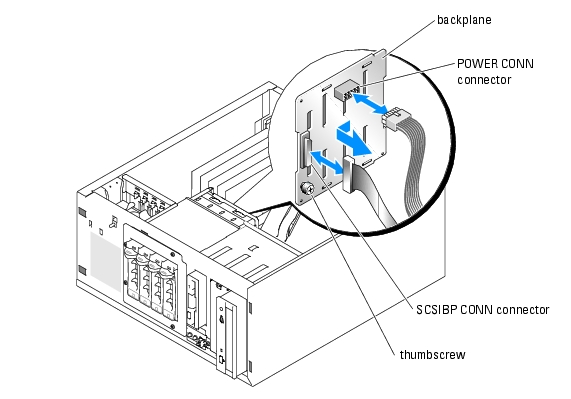
SCSI Backplane Board
The hard-drive bay provides space for up to four 1-inch SCSI hard drives. The SCSI backplane board connects the hard drives in the hard-drive bay to the SCSI or RAID controller.
|
NOTE: The SCSI backplane board does not support SATA hard drives.
|
Removing the SCSI Backplane Board
|
|
CAUTION: See the System Information Guide for complete information about safety precautions, working inside the computer, and protecting against electrostatic discharge. |
- Turn off the system and attached peripherals, and disconnect the system from the electrical
outlet.
- Open the system.
- Disconnect the following cables from the backplane board:
- The DC power cable from the POWER CONN connector
- The SCSI cable from the SCSIBP CONN connector
- Remove the SCSI hard drives from the hard-drive bay.
- Loosen the thumbscrew that secures the backplane board to the chassis. See Figure 1-1.
- Slide the backplane board toward the external drive bay about 12.7 mm (0.5 inch), and then
pull the backplane board away, off its grounding tabs (toward the back of the system), and out
of the chassis.
Figure 1-1. Removing the Backplane Board
Installing the SCSI Backplane Board
|
|
CAUTION: See the System Information Guide for complete information about safety precautions, working inside the computer, and protecting against electrostatic discharge. |
- Align the backplane board mounting holes with the grounding tabs inside the chassis.
- Insert the backplane board into the system chassis, and slide the backplane board toward the
front fan about 12.7 mm (0.5 inch).
- Tighten the thumbscrew that secures the backplane board to the chassis.
- Reconnect the following cables to the backplane board:
- The DC power cable to the POWER CONN connector
- The SCSI cable to the SCSIBP CONN connector
- Install the SCSI drives into the hard-drive bay.
- Close the system.
- Reconnect the system to its electrical outlet and turn the system on, including any attached
peripherals.
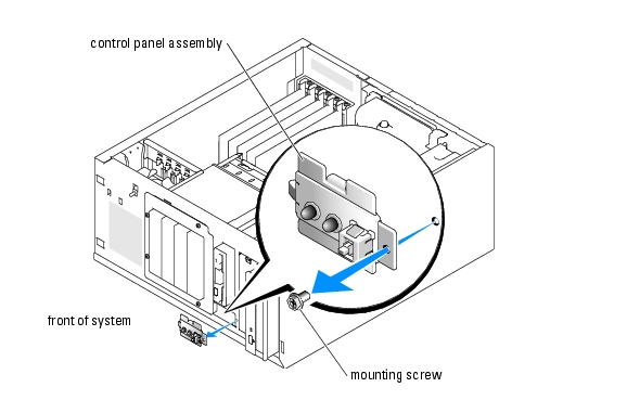
Control Panel Assembly
The control panel assembly contains the power button, power indicator, and hard-drive activity indicator.
Removing the Control Panel Assembly
|
|
CAUTION: See the System Information Guide for complete information about safety precautions, working inside the computer, and protecting against electrostatic discharge. |
|
NOTE: See the Installation and Troubleshooting Guide to identify the system board connectors.
|
- Turn off the system and attached peripherals, and disconnect the system from the electrical
outlet.
- Open the system.
- Disconnect the control panel assembly cable from the FRONT_PANEL connector on the
system board.
- Using a #2 Phillips screwdriver, remove the mounting screw that secures the control panel
assembly to the chassis and lift the control panel and its cable assembly away from the system.
See Figure 1-2.
Figure 1-2. Removing the Control Panel Assembly
Installing the Control Panel Assembly
- Insert the control panel cable connector through the front of the system and connect the
cable connector to the FRONT_PANEL connector on the system board.
- Insert the control panel mounting tab into the system chassis and align the mounting holes
on the chassis and control panel.
- Using a #2 Phillips screwdriver, install the screw that secures the control panel assembly to
the chassis.
- Close the system.
- Reconnect the system to its electrical outlet and turn the system on, including any attached
peripherals.
Chassis-Intrusion Switch
The chassis intrusion switch detects when the system cover is removed and logs the intrusion in the chassis-intrusion detector in the System Setup program.
To reset the chassis-intrusion detector, see "Resetting the Chassis-Intrusion Detector."
Removing the Chassis-Intrusion Switch
|
|
CAUTION: See the System Information Guide for complete information about safety precautions, working inside the computer, and protecting against electrostatic discharge. |
|
NOTE: See the Installation and Troubleshooting Guide to identify the system board connectors.
|
- Turn off the system and attached peripherals, and disconnect the system from the electrical
outlet.
- Open the system.
- Disconnect the fan cable from the FRONT_FAN connector on the system board.
- Remove the front fan assembly.
- Disconnect the chassis intrusion switch cable from the INTRUSION_SWITCH connector on
the system board.
- Slide the chassis-intrusion switch out of its slot, and lift the switch assembly away from the
system until the fan cable and connector are clear of the routing hole in the expansion-card
guide bracket. See Figure 1-3.
Figure 1-3. Removing the Chassis-Intrusion Switch

Replacing the Chassis Intrusion Switch
- Insert the chassis-intrusion switch cable into the routing hole in the expansion-card guide
bracket.
- Connect the chassis-intrusion switch cable to the INTRUSION_SWITCH connector on the
system board. See Figure 1-3.
- Insert the fan cable into the routing hole in the expansion-card guide bracket.
- Install the front fan assembly.
- Pull the fan cable through the routing hole in the expansion-card guide bracket.
- Connect the fan cable to the FRONT_FAN connector on the system board. See Figure 1-3.
- Close the system.
- Reconnect the system to its electrical outlet and turn the system on, including any attached
peripherals.
Resetting the Chassis-Intrusion Detector
- Turn on the system.
- Enter the System Setup program by pressing <F2> during POST.
|
NOTE: See the system User's Guide for instructions on using the System Setup program.
|
- Select System Security by pressing the up- or down-arrow key and press <Enter>.
- Select Chassis Intrusion by pressing the up- or down-arrow key and press <Enter>.
- Reset the Chassis Intrusion option by pressing the left- or right-arrow key to select Enabled,
Enabled-Silent, or Disabled.
|
NOTE: The default is Enabled.
|
|
NOTE: If a setup password has been assigned by someone else, contact the network administrator
for information on resetting the chassis-intrusion detector.
|
- Press <Esc> twice to exit the System Setup program, restart the system, and implement your
changes.
Power Supply
Removing the Power Supply
|
|
CAUTION: See the System Information Guide for complete information about safety precautions, working inside the computer, and protecting against electrostatic discharge. |
|
NOTE: See the Installation and Troubleshooting Guide to identify the system board connectors.
|
- Turn off the system and attached peripherals, and disconnect the system from the electrical
outlet.
- Open the system.
- Disconnect the DC power cables from the following components:
- POWER CONN connector on the backplane board (if applicable)
- PWR CONN and 12V connectors on the system board
- Hard drives
- Diskette drive (if applicable)
- CD, DVD, or CD-RW/DVD drive (if applicable)
- Tape backup drive (if applicable)
- Remove the cooling shroud.
- Disconnect the fan cable from the BACK_FAN connector on the system board.
- Pull the release tab on the fan assembly away from the back panel and slide the fan assembly
about 0.63 cm (0.25 inch) toward the expansion-card slots.
- Pull the fan assembly forward and lift the assembly out of the system.
- Remove the four screws securing the power supply to the back panel. See Figure 1-4.
Figure 1-4. Removing the Power Supply
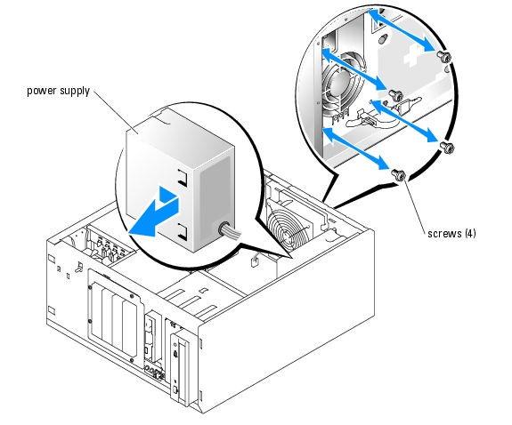
- Slide the power supply toward the front of the system approximately 2 cm (1 inch).
- Lift the power supply up and out of the system.
Replacing the Power Supply
- Insert the power supply into the system and align the mounting holes with the holes on the
back panel.
- Install the four screws securing the power supply to the back panel.
- Align the tabs on the cooling fan bracket with the mounting holes in the back panel and slide
the fan assembly toward the power supply about 0.63 cm (0.25 inch) until the fan bracket
release tab snaps into place.
- Connect the fan cable to the BACK_FAN connector on the system board.
- Install the cooling shroud.
- Connect the DC power cables to the following components:
- POWER CONN connector on the backplane board (if applicable)
- PWR CONN and 12V connectors on the system board
- Hard drives
- Diskette drive (if applicable)
- CD, DVD, or CD-RW/DVD drive (if applicable)
- Tape backup drive (if applicable)
- Close the system.
- Reconnect the system to its electrical outlet and turn the system on, including any attached
peripherals.
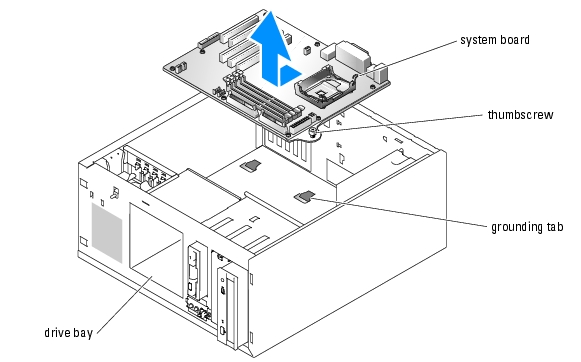
System Board
The system board provides interface signal routing between the system board and the SCSI hard-drive bay, the CD, DVD, or CD-RW/DVD drive, the diskette and tape drives (if applicable), and the control panel.
The system board and system board tray are removed and replaced as a single assembly.
|
|
CAUTION: See the System Information Guide for complete information about safety precautions, working inside the computer, and protecting against electrostatic discharge. |
|
|
CAUTION: The heat sink can get hot during operation. To avoid burns, ensure that the system has sufficient time to cool before removing the system board. |
Removing the System Board
- Turn off the system and attached peripherals, and disconnect the system from the electrical
outlet.
- Disconnect the cables to the I/O connectors on the back panel.
- Open the system.
- Disconnect the DC power and interface cable(s) from the hard drives or SCSI backplane
board.
- Remove the hard drives and drive bay.
- Remove the cooling shroud.
- Disconnect all cables attached to the system board:
- CD, DVD, or CD-RW/DVD drive interface cable (the PRIMARY_IDE connector on the system board)
- Diskette drive cable (the FDD connector on the system board)
- Control panel cable (the FRONT_PANEL connector on the system board)
- Chassis intrusion switch cable (the INTRUSION_SWITCH connector on the system board)
- Front fan cable (the FRONT_FAN connector on the system board)
- Back fan cable (the BACK_FAN connector on the system board)
- Any other cables attached to the system board, after recording their locations
- Remove the back fan.
- Remove the SCSI backplane board (if applicable). See "Removing the SCSI Backplane
Board."
- Remove the memory modules.
|
NOTE: Record the memory module socket locations to ensure proper installation.
|
- Remove all PCI expansion cards and any attached interface cables from the expansion slots.
- Remove the retention clips that secure the heat sink to the retention module.
 |
NOTICE: The processor and heat sink can become extremely hot. Allow sufficient time for the processor
and heat sink to cool before handling.
|
|
NOTICE: To prevent damaging the processor, do not pry the processor off the heat sink.
|
- Rotate the heat sink slightly to separate the heat sink from the processor, and then gently lift
the heat sink off the processor.
|
NOTE: Remove the heat sink while the processor is still warm.
|
|
NOTICE: Be careful not to bend any of the pins when removing the processor. Bending the pins can
permanently damage the processor.
|
- Remove the processor.
- Loosen the thumbscrew that secures the system board tray to the chassis.
- Slide the system board toward the front of the chassis about 6.3 mm (0.25 inch).
- Carefully lift the system board up and out of the chassis. See Figure 1-5.
Figure 1-5. Removing the System Board
Installing the System Board
|
NOTE: The new system board includes a new system board tray.
|
- Unpack the new system board.
- Lower the system board into the chassis, and press the system board evenly onto all of the
grounding tabs on the floor of the chassis. See Figure 1-5.
- Slide the system board toward the back of the chassis as far as it will go, about 6.3 mm (0.25
inch).
- Tighten the thumbscrew that secures the system board tray to the chassis.
- Ensure that the system board jumpers are set the same as on the board that you removed.
- Ensure that the processor socket release lever is in the fully open position.
|
NOTICE: Positioning the processor incorrectly can permanently damage the processor and the system
when you turn on the system. When placing the processor in the socket, be sure that all of the pins on the
processor go into the corresponding holes. Be careful not to bend the pins.
|
- Align pin 1 on the processor with pin 1 on the processor socket.
- Carefully install the processor in the socket and press it down lightly to seat it.
|
NOTE: No force is needed to install the processor in the socket. When the processor is aligned
correctly, it should drop into the socket.
|
- Locate the thermal grease packet that is included with your new system board.
- Apply the thermal grease to the heat sink, lower the heat sink onto the processor, and secure
the heat sink to the retention module.
|
NOTICE: Do not operate the system without the heat sink installed. The heat sink is required to maintain
proper thermal conditions.
|
|
NOTE: If you are installing a low-profile heat sink, install the heat sink in the retention module with
the cooling tubes pointing toward the center of the system.
|
- Install all PCI expansion cards into the expansion slots and connect their interface cables to
the appropriate components in the system.
- Install the memory modules.
- Install the SCSI backplane board (if applicable). See "Installing the SCSI Backplane Board."
- Install the back fan and connect the fan cable to the BACK_FAN connector on the system
board.
- Connect all remaining cables to the system board:
- Front fan cable to the FRONT_FAN connector
- Chassis intrusion switch cable to the INTRUSION_SWITCH connector
- Control panel cable to the FRONT_PANEL connector
- Diskette drive cable to the FDD connector
- CD, DVD, or CD-RW/DVD drive interface cable to the PRIMARY_IDE connector
- Any other cables that were attached to the previous system board
- Install the cooling shroud.
- Install the drive bay and hard drives. If SCSI drives are installed, close the hard-drive carrier
handles to lock the drives in place.
- Connect the DC power and interface cable(s) to the hard drives or SCSI backplane board.
- Carefully check for any cables or components that are not installed or improperly seated in
their connectors on the system board.
- Close the system.
- Reconnect the system to its electrical outlet and turn the system on, including any attached
peripherals.
Back to Contents Page