Back to Contents Page
Introduction
Dell™ PowerConnect™ 2216/2224/2324 Switches
User's Guide
 Package Contents
Front Panel Indicators
Connecting Devices
Typical Deployments
Class-of-Service
Mounting Kit Instructions
Technical Information
Dell™ PowerConnect™ switches provide 10/100-Mbps Gigabit or 10/100/1000-Mbps Gigabit Ethernet connectivity. The switches have the following features:
- Switch ports
- PowerConnect 2216 — 16 ports, 10/100-Mbps Gigabit
- PowerConnect 2224 — 24 ports, 10/100-Mbps Gigabit
- PowerConnect 2324 — 24 ports, plus two additional RJ-45 Gigabit Ethernet ports, 10/100/1000-Mbps Gigabit.
- Complies with IEEE 802.3 10Base-T, IEEE 802.3u 100Base-TX, IEEE 802.3z/ab 1000Base-T
- Tag-based IEEE 802.1p Class-of-Service with two priority queues per port
- IEEE 802.3x PAUSE frames flow control in full-duplex operation
- Automatic negotiation for speed and full- and half-duplex mode on all ports
- Backpressure flow control in half-duplex operation
- Collision detection on all ports
- Auto MDI/MDIX
- 8K MAC address entries supported
- Comprehensive LED indicator panel to monitor overall switching condition
- 19-inch rackmountable and wallmountable, standard 1U chassis
- Internal power supply
Package Contents
Before you install a switch, verify that your package contains the following items:
- Switch
- Self-adhesive rubber pads for desktop installation
- Kit for 19-inch rack installation
- Kit for wallmount installation of 16- and 24-port switches
- PowerConnect 2216/2224/2324 Switches CD
- AC power cord
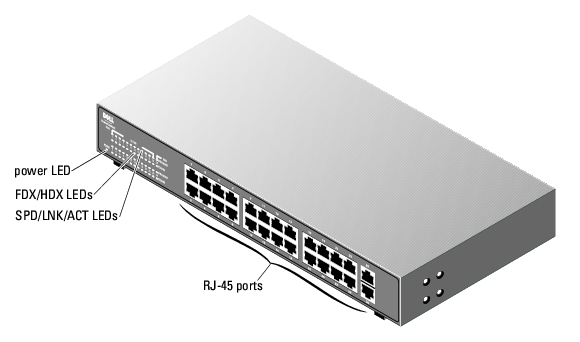
Front Panel Indicators
Your PowerConnect switch contains two rows of LEDS that provide information about connection speed, data activity, and duplex operation mode.
Power (POWER) LED
- Green — The switch is powered on.
- Off — The switch is off.
10/100 Ports Link/Activity (SPD/LNK/ACT) LED
- Steady green — A 100-Mbps link has been established, but no data is being transmitted or received.
- Blinking green — A 100-Mbps link has been established and data is being transmitted or received.
- Steady amber — A 10-Mbps link has been established, but no data is being transmitted or received.
- Blinking amber — A 10-Mbps link has been established and data is being transmitted or received.
- Off — No link has been established.
10/100/1000 Ports Link/Activity (SPD/LNK/ACT) LED (2324 only)
- Steady green — A 1000-Mbps link has been established, but no data is being transmitted or received.
- Blinking green — A 1000-Mbps link has been established and data is being transmitted or received.
- Steady amber — A 10-Mbps or 100-Mbps link has been established, but no data is being transmitted or received.
- Blinking amber — A 10-Mbps or 100-Mbps link has been established and data is being transmitted or received.
- Off — No link has been established.
Duplex Mode/Collisions (FDX/HDX) LED
- Steady green — The port is operating in full-duplex mode.
- Blinking green — Collisions are occurring on the port.
- Off — The port is operating in half-duplex mode.
Figure 1-1. PowerConnect 2216

Figure 1-2. PowerConnect 2224
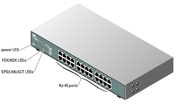
Figure 1-3. PowerConnect 2324
Connecting Devices
RJ-45 Switch Ports
RJ-45 connectors are located on the front panel of the switch.
 |
NOTE: Ensure that Category 5E (CAT 5E) cabling is used for connecting devices at 1000-Mbps Gigabit
Ethernet speed.
|
All ports can negotiate full- and half-duplex modes automatically. These switching ports allow users to connect the switches to 10Base-T and 100Base-T on ports 1-16 (2216), ports 1-24 (2224, 2324) and 1000Base-T devices on uplink ports 25 and 26 on the 2324.
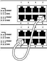
Connecting Two or More Switches Together
Each port supports Auto MDI and MDIX functionality. When cascading with other switches or hubs, each port can connect directly to a switch or hub with straight-through twisted-pair cable (see Figure 1-4).
|
NOTE: Do not connect two switches together with more than one cable. Using multiple cables to
connect switches can create a loop and cause collisions.
|
Figure 1-4. Cascading Switches
Connecting Switches to Other Devices
By connecting a switch to other devices, you can form a small network. All the RJ-45 ports support Auto MDI/MDIX and therefore automatically detect the type of cable used to connect the network device. Crossover or straight-through networking cables can be used to connect PCs as well as other networking devices like hubs or routers to the switch. All ports on the switch automatically negotiate speed and whether to operate in full duplex or half duplex.
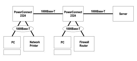
Typical Deployments
Your switch can be deployed in small and large workgroups. Figure 1-5 depicts a typical small workgroup network that has a limited number of attached devices. Figure 1-6 Figure 1.6 depicts a typical large workgroup that has several groups of individuals not all working in the same physical area.
Figure 1-5. Small Workgroup
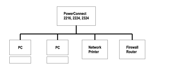
Figure 1-6. Large Workgroup
Class-of-Service
The switch supports tag-based prioritization following the IEEE 802.1p standard. The eight levels of IEEE 802.1p priority are mapped to the two priority queues of each port. For each port, the two priority queues are scheduled following a Weighted Round Robin scheme.
Table 1-1. Tag-Based Prioritization
|
IEEE 802.1p Priority
|
Priority Queue
|
Scheduling Weight
|
|---|
0-3 | 0 | 1 |
4-7 | 1 | 4 |
|
NOTE: The IEEE 802.1p priority information is part of the IEEE 802.1q tag that also defines VLAN
memberships. The switches will ignore the VLAN membership information in the tag (that is, all ports are
part of all VLANs), but will preserve the full tag information—including packet priority and VLAN ID—
when transmitting the packet at the destination port.
|
Mounting Kit Instructions
The switches come with mounting brackets and screws for rackmounting or wallmounting and rubber feet for stationing on a flat surface.
Installing the Switch on a Flat Surface
The switch can be installed on any appropriate level surface that can safely support the weight of the switches and their attached cables. There must be adequate space around the switch for ventilation and access to cable connectors.
To install the switch on a flat surface, complete the following steps:
- Set the switch on the flat surface and check for proper ventilation.
Allow at least 5.1 cm (2 inches) on each side for proper ventilation and 12.7 cm (5 inches) at the back for power cable clearance.
- Attach rubber feet on each marked location on the bottom of the chassis.
The rubber feet are optional, but are recommended to keep the switch from slipping.
Installing the Switch in a Rack
The switch can be installed in Dell PowerEdge™ racks, which are 48.3 cm (19 inches). It can also be installed in most other standard 19-inch racks and most telco two-post racks.
|
NOTE: Do not install rubber feet on the switch if you are rackmounting the switch.
|
To install the switch in a rack, complete the following steps:
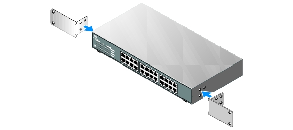
- Use the supplied screws to attach a mounting bracket to each side of the switch (see
Figure 1-7).
Figure 1-7. Brackets for Rack Installation
- Install the cage nuts onto the mounting rails of your rack, if your rack requires them.
|
NOTE: Additional screws are provided for racks that have threaded mounting holes.
|
- Position the switch in the rack and align the holes in the mounting bracket with the holes in
the rack.
- Insert and tighten two screws appropriate for your rack through each of the mounting
brackets.
Installing the Switch on a Wall
To mount the switch on a wall, complete the following steps:
- Ensure that the mounting point meets the following requirements:
- The wall surface must be capable of supporting the switch.
- Allow at least 5.1 cm (2 inches) on each side for proper ventilation and 12.7 cm (5 inches) at the back for power cable clearance.
- The location must not be located in direct sunlight.
- The location must not be within 2 feet of any heating vents, nor should any area heating vent point toward the unit.
- The location must be ventilated to prevent heat buildup.
- Do not locate the switch where there may be data or electrical cabling located directly behind the unit.
- The power cable must reach an outlet.
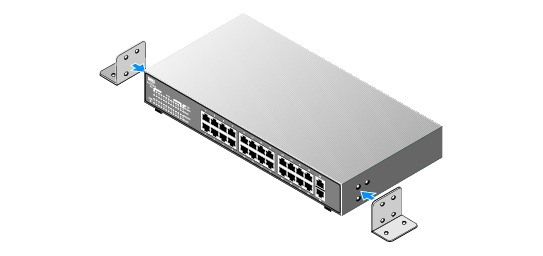
- Use the supplied screws to attach a mounting bracket to each side of the switch (see
Figure 1-8).
Figure 1-8. Brackets for Wall Installation
- Place the switch against the wall and mark the wall through the holes of the brackets.
- Drill holes in the wall for the brackets and install the appropriate mounting hardware (not
supplied).
- Place the switch against the wall so that the bracket holes align with the holes in the wall.
- Insert and tighten the screws through each of the mounting brackets.
Technical Information
Table 1-2. Specifications
|
Network Protocol and Standards Compatibility
|
IEEE 802.3 CSMA/CD |
IEEE 802.3 10Base-T |
IEEE 802.3u 100Base-TX |
IEEE 802.3z/ab 1000Base-T |
IEEE 802.3x Flow Control |
IEEE 802.3p Priority |
|
Interface
|
RJ-45 connectors |
|
Power Supply
|
PowerConnect 2216 | Supply voltage: 100-240 VAC
Frequency: 50-60 Hz
Current consumption: 0.4A |
PowerConnect 2224 | Supply voltage: 100-240 VAC
Frequency: 50-60 Hz
Current consumption: 0.75A |
PowerConnect 2324 | Supply voltage: 100-240 VAC
Frequency: 50-60 Hz
Current consumption: 0.75A |
|
Physical Dimensions
|
PowerConnect 2216 | 266 x 161 x 43 mm (W x D x H)
10.5 x 6.3 x 1.7 inches
Unit Weight: 3.0 Lbs
Packaged Weight: 3.3 Lbs (6 per container) |
PowerConnect 2224 | 328 x 231 x 43 mm (W x D x H)
13 x 9 x 1.7 inches
Unit Weight: 4.8 Lbs
Packaged Weight: 5.24 Lbs (5 per container) |
PowerConnect 2324 | 328 x 231 x 43 mm (W x D x H)
13 x 9 x 1.7 inches
Unit Weight: 5.1 Lbs
Packaged Weight: 5.46 Lbs (5 per container) |
|
Environmental Specifications
|
Operating temperature | 0º to 40ºC (32º to 104ºF) |
Storage temperature | –20º to 70ºC (–4º to 158ºF) |
Operating Relative Humidity | 10% to 90% non-condensing |
Storage Relative Humidity | 10% to 95% non-condensing |
Back to Contents Page