Back to Contents Page
Dell™ PowerConnect™ 3024 Systems
User's Guide
 Features
Front Panel Indicators
Rear Panel Descriptions
Management
The PowerConnect 3024 Fast Ethernet Managed Switch offers the following features:
- IP Assignment Mode
- SNMP Host Authorization Table
- User Authentication Mode — RADIUS Server IP Address, RADIUS Shared Secret, IP Filtering, and Allowed IP Addresses
- Layer 3 Priority — DiffServ
- Configuration File Management
- Enhanced Security Administration
- More Statistics/Utilization Summary
- 24 10/100BASE-T auto-sensing Fast Ethernet switching ports
- 2 10/100/1000BASE-T auto-sensing Gigabit Ethernet switching ports, each with a matching gigabit interface converter (GBIC) slot
- 2 gigabit stacking ports for daisy-chain stacking of up to 6 units
- IEEE 802.3u, IEEE 802.3z, and IEEE 802.3ab compliant
- Up to 8K-entry, media access control (MAC) address cache with hardware-assisted aging
- IEEE 802.3x flow control for full duplex operation
- IEEE 802.1Q based tagged VLAN
- IEEE 802.1p class of service (CoS) through dual priority queues for each port
- IEEE 802.3ad link aggregation: up to 4 aggregated trunks per switch
- Spanning tree protocol
- Internet group management protocol (IGMP) snooping support
- Back pressure flow control for half-duplex operation
- Port mirroring
- Auto MDI/MDIX support for the 10/100BASE-T and the 10/100/1000BASE-T ports
- MAC addresses lookup based on port, virtual local area network (VLAN) ID, and MAC addresses
- System LED and per port LEDs
- Standard 1U chassis
- 19-inch rack-mountable
- 3024/3024 mixed stack supported
- Web-based management with embedded HTTP server
- Text-based management through 3 in-band Telnet sessions, and an out-of-band RS232 console port (VT100)
- Simple network management protocol (SNMP)-based network management via an SNMP management console application
- Network boot and software upload via TFTP
- Hardware assisted remote monitoring (RMON) statistic collection
- Management information base (MIB) II (RFC1213)
- Ethernet Interface MIB (RFC1643)
- Bridge MIB (RFC1493)
- 4-Group RMON (RFC1757)
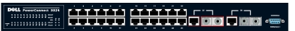
The front panel of the system contains the console port, all of the Ethernet ports, and the LEDs. As shown in the figure below, there are one system LED, two LEDs for each Fast Ethernet port, and three LEDs for each Gigabit Ethernet port on the switch. The following sections describe the front panel in more detail.
The power LED shows the general operating status of the system as reflected by the following indicators:
- Off — The unit is off.
- Green — The unit is on and ready for operation.
- Yellow — The unit is in boot mode.
- Blinking Yellow — The unit fails during initialization.
The normal sequence after power-on or system reset is Green (initialization success), Yellow (booting applications), and Green again (system ready).
The console interface can be accessed from the RS232 serial port or a telnet connection. The console port uses a standard null-modem cable. For instructions on configuring your switch using the console, see "Console Interface."
Two LEDs show the operating status of each Fast Ethernet port and three LEDs show the operating status of each Gigabit Ethernet port as reflected by the indicators in each of the following sections:
- Green — A 100-Mbps link is up and there is no activity.
- Blinking Green — A 100-Mbps link is up and there is activity.
- Yellow — A 10-Mbps link is up and there is no activity.
- Blinking Yellow — A 10-Mbps link is up and there is activity.
- Off — The link is down.
- Green — A full-duplex link is up.
- Yellow — A half-duplex link is up and no collisions are occurring.
- Blinking Yellow — A half-duplex link is up and collisions are occurring.
- Off — The link is down.
- Green — A 1000-Mbps link is up and there is no activity.
- Blinking Green — A 1000-Mbps link is up and there is activity.
- Off — A 10/100-Mbps link is up or the link is down.
- Green — A 100-Mbps link is up and there is no activity.
- Blinking Green — A 100-Mbps link is up and there is activity.
- Yellow — A 10-Mbps link is up and there is no activity.
- Blinking Yellow — A 10-Mbps link is up and there is activity.
- Off — The link is down.
- Green — A full-duplex link is up.
- Yellow — A half-duplex link is up and no collisions are occurring.
- Blinking Yellow — A half-duplex link is up and collisions are occurring.
- Off — The link is down.
The rear panel of the system contains the two Gigabit stacking ports and an AC power receptacle.

The switch automatically adjusts its power setting to any supply voltage in the range 90-240 volt AC.
The following sections describe methods you can use to manage the switch.
After you have successfully installed the switch, you can configure the switch, monitor the LED panel, and display statistics graphically using a web browser like Netscape Navigator version 6.0 and higher or Microsoft IE version 4.01 and higher.
 |
NOTE: To access to the
switch via a web browser,
the PC running the web
browser must have IP-
based network access to
the switch.
|
You can also connect a computer or terminal to the serial console port or use Telnet to access the switch. The interface is menu-driven so you do not need to use a complex command syntax. The menus are similar to those in the web interface. For more information, see "Console Interface."
You can manage the switch with an SNMP-compatible console application. The switch is compatible with SNMP version 1.0.
The SNMP agent decodes the incoming SNMP messages and responds to these requests with MIB objects stored in the database. For statistics and counters, the SNMP agent updates the MIB objects every 5 seconds.
The switch supports a comprehensive set of MIB extensions as the following list indicates:
- MIB II
- Ethernet Interface MIB
- Bridge MIB
- 4 RMON groups
- Ethernet statistics group
- Ethernet history group
- Alarm group
- Event group
Back to Contents Page