Dell™ PowerConnect™ 3024 Systems User's Guide
You can access the console, using VT100 terminal emulation, from the RS232 serial port or a telnet connection. The switch offers password protection for this interface.
When the telnet session opens, select Terminal->Properties. In the Terminal Preferences dialog, verify the following settings:
 |
NOTICE: When using HyperTerminal with Windows 2000, make sure that you have Windows 2000 Service Pack 2 or later installed. Windows 2000 Service Pack 2 fixes the problem of arrow keys not functioning in HyperTerminal's VT100 emulation. See www.microsoft.com for information on Windows 2000 service packs. |
The switch offers a menu-driven console interface. Use the arrow keys to move within menus and sub-screens. To select a menu, press the appropriate <arrow> key to highlight the menu, and then press <Enter>. You can also type the letter in front of each menu option to select that option.
The bottom of every screen displays key commands available for that particular screen and sometimes other helpful information. The following list describes common key commands:
Once you configure your system terminal and start the switch, you can log in to the console interface. The first time you log in, you must use the default password, which is switch.
The bottom of most screens includes information about navigating in and issuing commands from the console interface. In general, the following information applies:
You can manage a stack of up to six units through the console interface. On most pages, you must select the unit in the stack you want to display. Use the arrow keys to navigate to the unit to display and press <Enter>. Press <Esc> to go back to unit selection.
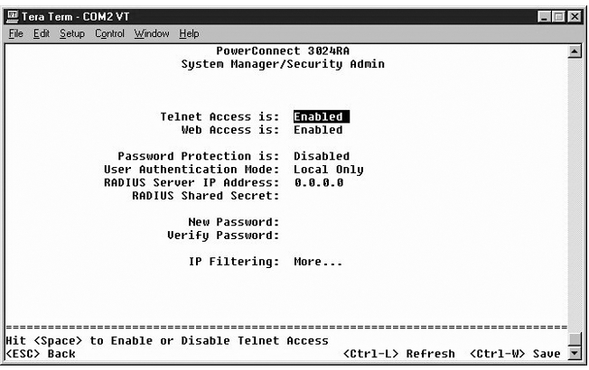
From the initial welcome screen, you must enter a password to proceed, if password protection is enabled. If password protection is disabled, the Main Menu is displayed and you immediately have access to the switch management interface. By default, password protection is disabled. If enabled, the default password is switch. For more information about password protection, see "Security Admin."
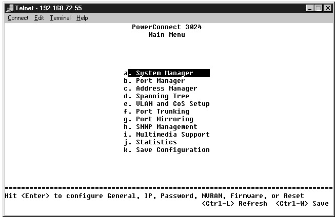
The main menu displays all the sub-menus and pages that are available.
The following menu items are available:
To log out of the user interface, press <Ctrl><d> at any time during your telnet session. This returns you to the login screen.
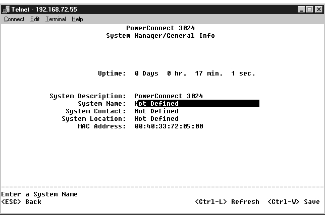
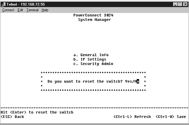
The system manager contains all system operations and general information. It includes the following menus:
The General Info screen contains the following information:
It also includes the following editable fields:
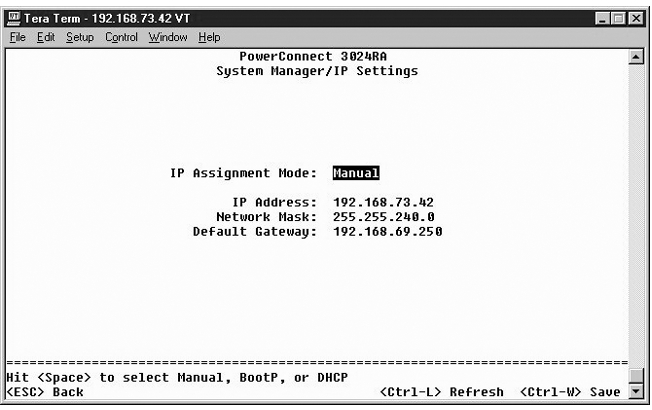
This menu manages the IP-related information about the system.
The IP Settings page includes the following editable fields:
Press <Ctrl><w> to save any changes made. Press <ESC> and select Reset to reboot the system.
 |
NOTE: You must reboot the system from the System Manager/Reset page for the changes to take effect. |
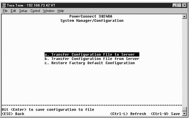
See "Installation" for more information on installation.
|
NOTE: The default password is switch. |
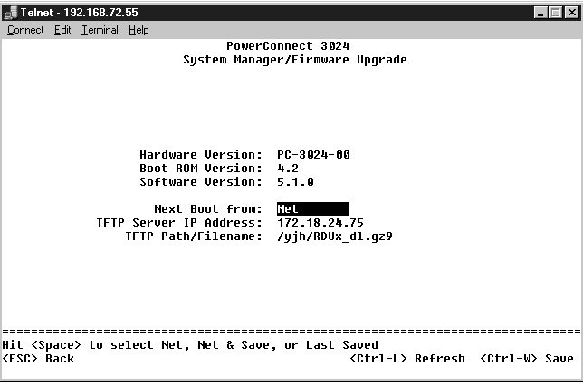
From the Firmware Upgrade screen, you can configure the system to download a new version of the management software. You can also set the system to use the new software without overwriting the previous version. See "Software Upgrades" for more information about this process.
The Firmware Upgrade screen contains the following information:
It also contains the following editable fields:
|
NOTICE: For changes to persist beyond the current session, you must save the new configuration from the Save Configuration page. You must reboot the system from the System Manager/Reset page to start the firmware upgrade. |
If you make any changes to the system through the console interface, you must save the changes in the Save Configuration screen. Once you save changes in this screen, you must go to the Reset screen and select the Reset menu option to reboot the system before the changes can take effect.
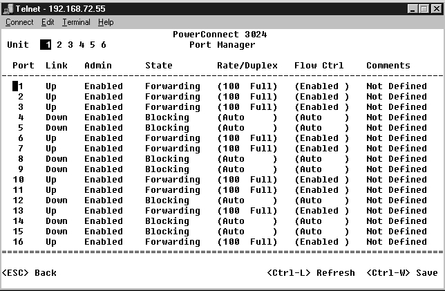
You can arrange the port characteristics related to link operations. To change settings for any parameter on this page, select the current value and press the space bar. This toggles between the available values for the parameter.
For each port number listed under the Port column, you can change the following parameters listed by column name on the screen:
To enable a GBIC module instead of the built-in 10/100/1000BASE-T port for a Gigabit Ethernet uplink, navigate to the desired port number and press the spacebar to enable the GBIC module.
|
NOTICE: Enabling the GBIC port disables the associated built-in 10/100/1000BASE-T port. |
The Address Manager screen includes the following options:
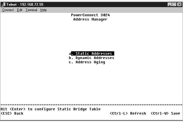
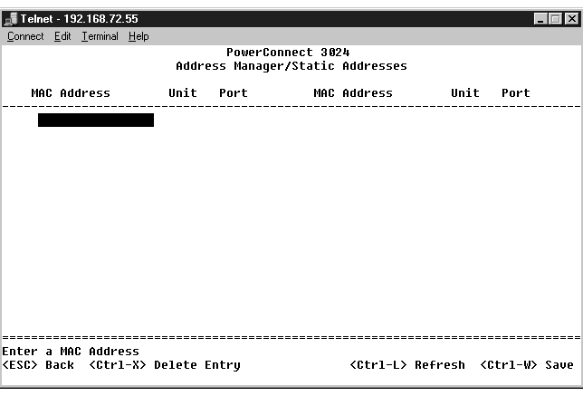
From the Static Addresses screen, you can specify the MAC address and port number of systems that are to remain available to the switch for an indeterminate amount of time.
The following information is required to add a static MAC address:
If all the information is correct, the new entry appears in the screen in order by port ID.
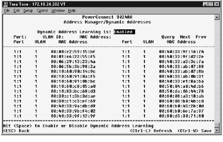
The Dynamic Addresses lookup table allows you to view the MAC addresses that are currently in the address database. When addresses are in the database, the packets intended for those addresses are forwarded directly to those ports. You can filter out the table by port, VLAN, and MAC address by checking those fields.
Dynamic MAC address learning is enabled by default. This is the standard mode for a network switch. In some networks, you may want to create a secured network by disabling the dynamic address learning capabilities. When this is done, all current dynamic address entries will be locked in. These addresses will not age out and new addresses will not be learned.
In addition, if a new address is detected on a port, the switch will disable the port with the new address, save the current settings to NVRAM, and send out a Simple Network Management Protocol (SNMP) trap warning. This is useful for locking out systems that attempt to access the network that were not on the network previous to the lockdown. Once a port is automatically disabled, you can reenable the port manually. The NVRAM will only be saved the first time a given port detects a new address. If the aging time is raised prior to disabling the dynamic address learning, it will allow enough time for all current MAC address to be learned by the switch without the possibility of aging out.
|
NOTE: The console interface can display up to 28 address entries. To see more than 28 entries, use the web interface. |
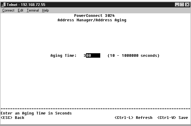
In the Address Aging screen, you can specify how long an address stays available to the switch if it is not configured as static.
The following field is available:
The Spanning Tree screen includes the following options:
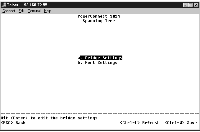
From the Bridge Settings screen, you can enable and configure the spanning tree. The following options are available:

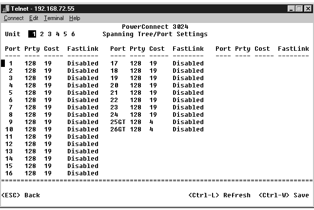
In the Port Settings screen, you can specify spanning tree parameters for each port. This screen is in a table format. For each port number listed under the Port column, the following fields are available:
|
NOTE: This option is useful if a device is connected to a port that requires network access immediately when the link comes up and cannot wait for a Spanning Tree resolution. |
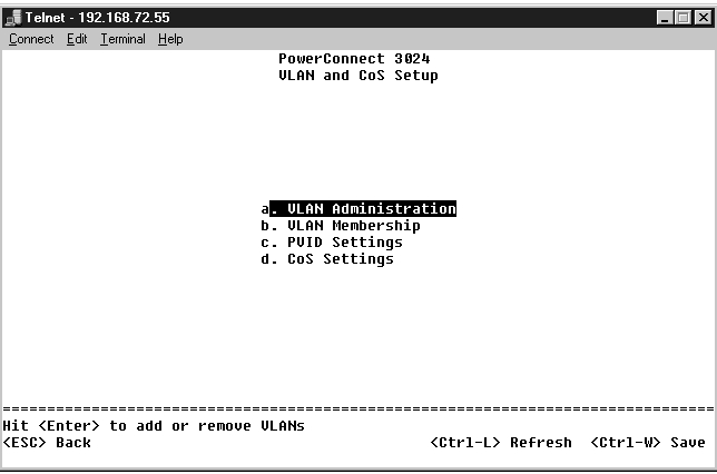
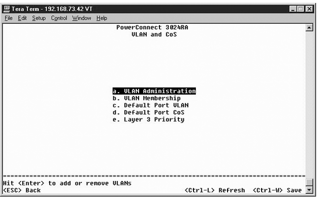
From the VLAN Management menu, you can configure up to 64 802.1Q VLANs.
VLANs allows PCs, workstations, and other resources, including printers and file servers, to be organized into logical, broadcast domains so that only devices within the same domain can communicate with each other.
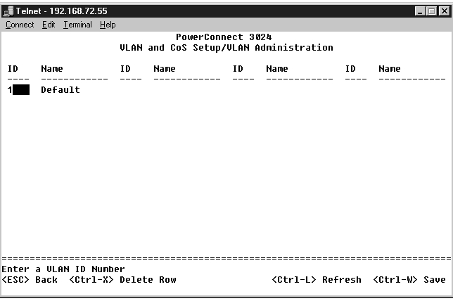
The VLAN Management screen shows the information regarding all configured VLANs. All ports of the switch are configured as untagged members in VLAN 1 with VLAN ID 1 by default. Users can create VLANs, delete VLANs, or reset the VLAN configuration back to default in this menu.
The VLAN Setup screen includes the following options:
You can add up to 64 VLANs with unique ID numbers and names. VLAN ID numbers must be in the range of 1 to 4094.
To remove an entire VLAN, just press <Ctrl><x> anywhere on that line.
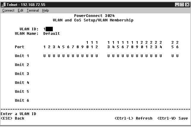
This matrix allows for real-time management of up to 64 VLANs. To add a port to a VLAN, position the cursor in the desired matrix location and toggle the options with the space bar.
The VLAN tagging option is a standard set by the IEEE to facilitate the spanning of VLANs across multiple switches. For more information, see the "Appendix" and IEEE Std 802.1Q-1998 Virtual Bridged Local Area Networks.
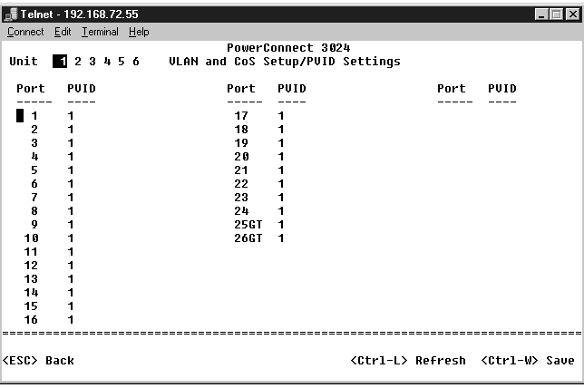
In the Port VLAN ID Setup screen, you can specify the PVID for each port on your switch. All untagged packets entering the switch are tagged by default with the ID specified by the port's PVID.
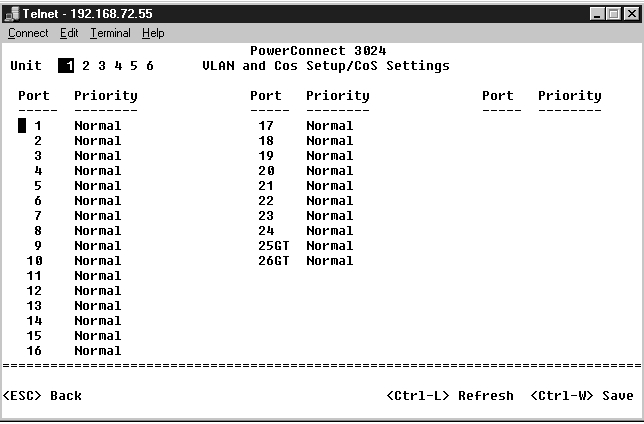
Port Priority allows the user to specify which ports have greater precedence in situations where traffic may be buffered in the switch due to congestion. The ports with a setting of "high" will transmit their packets before those with a "normal" setting. The settings on this page only affect ingress packets that are not already tagged for priority. To raise the priority of a given port, switch the port's setting from "normal" to "high". The default and normal setting for a port is "normal".
In the CoS Settings screen, you can specify the priority for each port on your switch.
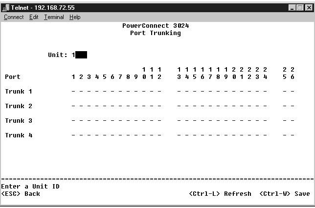
In the Port Trunking page, you can create multiple links between switches that work as one virtual, aggregate link. You can create four trunks at a time, with each trunk containing up to eight ports. Only ports of the same speed can belong to a single trunk: 10/100 Fast Ethernet ports and Gigabit Ethernet ports cannot be in the same trunk.
|
NOTICE: Fast Ethernet trunks can only include ports from a single eight-port cluster: Ports 1 to 8, ports 9 to 16, or ports 17 to 24. |
|
NOTICE: Built-in 10/100/1000BASE-T ports cannot be trunked with GBIC ports. |
To add a port to a trunk, click the toggle button below the port number until the correct trunk number appears.
Use the arrow keys to navigate to the port and trunk intersection that you want to edit. Press the spacebar to enable or disable trunking for the port and trunk you want.
|
NOTICE: All ports participating in a trunk must be operating in Full Duplex mode. |
|
NOTICE: All ports participating in a trunk should have the same VLAN and CoS settings. |
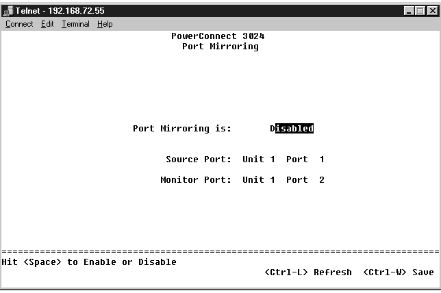
From the Port Mirroring menu, you can monitor traffic on a specific port. The switch can monitor only single direction traffic, either transmission or reception. When port mirroring is enabled, all the transmission or receiving traffic of the mirrored port is forwarded to the mirroring port.
The following options are available:
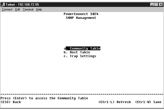
The SNMP menu includes the following options:
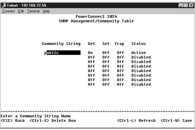
In the Community Table page, you can create different communities and customize access. The public string has Get privileges by default.
The following options are available:
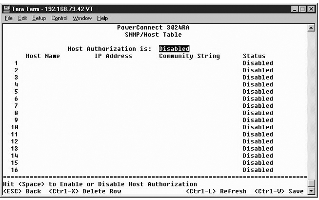
From the SNMP Host Table page, you can add and remove hosts from access rights that have been granted to community groups. The permissions GET, SET, and TRAP are assigned to a community name and then these permissions are assigned to individual machines by adding those machines and their IP addresses to the appropriate community string. Host authorization can be enabled or disabled.
If the host authorization is disabled (the default setting), the switch allows any SNMP manager to access the switch. If the host authorization is enabled, the administrator can specify up to 16 SNMP managers on the host table that can access the switch.
You must enable host authorization before you can use the host table. Host authorization is a security feature to limit people who are not listed in the host table from accessing the switch.
Once you have enabled host authorization, you must add the host to this table through the console port connection. Otherwise, the switch cannot access the end station using SNMP.
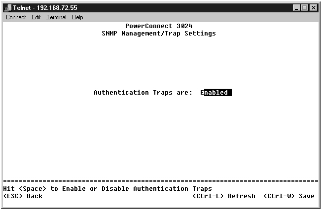
The SNMP Trap Setting allows for the setup of authentication traps. The following options are available:
All hosts in community strings with trap privileges are notified when a trap condition occurs.
There are two settings available from this page: IGMP and High Priority Optimization.
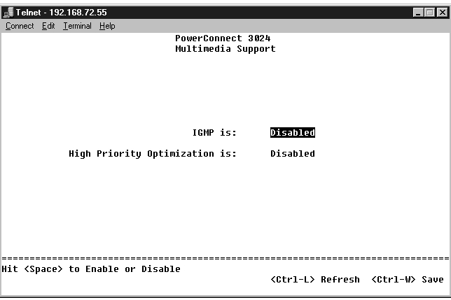
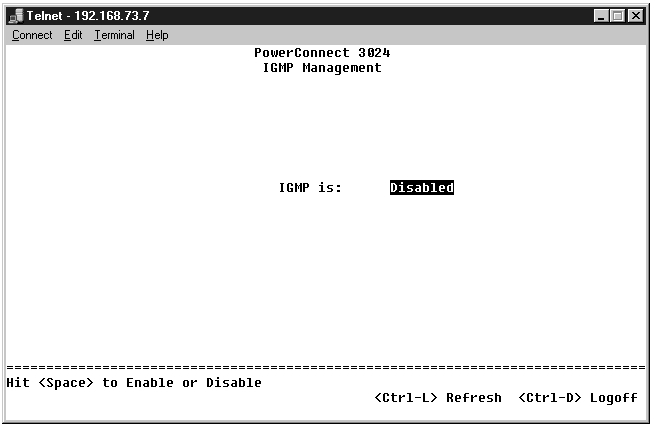
With IGMP (Internet Group Management Protocol) Snooping, you can configure the switch to forward multicast traffic intelligently. Based on the IGMP query and report messages, the switch forwards traffic only to the ports that request multicast traffic. This prevents the switch from broadcasting the traffic to all ports and possibly disrupting network performance.
|
NOTE: IGMP requires a router that learns about the presence of multicast groups on its subnets and keeps track of group membership. |
The IGMP option can be set as follows:
|
NOTICE: Enabling high-priority optimization can effectively disable flow- control for normal-priority packets. |
The High-Priority Optimization setting implements a priority-based head-of-line blocking prevention algorithm in the system. This algorithm ensures that in the case of traffic congestion, normal priority packets do not hold up high priority packets.
|
NOTE: Enabling high priority optimization can improve overall system performance for networks with time-sensitive, prioritized traffic; for example, the traffic associated with multimedia streaming, teleconferencing, or telephony applications. |
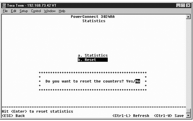
To view the statistics, select Statistics and hit the Enter key. Select Reset to reset the statistics settings.
|
NOTE: Counters are cumulative from the last time the system was booted. |