Back to Contents Page
Dell™ PowerConnect™ 3024 Systems
User's Guide
 Package Contents
Before You Connect to the Network: Mounting Kit Instructions
Connecting the Console Port
Password Protection
IP Address Assignment
Stacking
Connecting Devices to the Switch
Before you begin installing the switch, confirm that your package contains the following items:
- Switch
- Stacking cable
- AC power cord
- Null modem cable
- Self-adhesive rubber pads for desktop installation
- Rackmount kit for rack installation
- PowerConnect Systems System Information Guide
 |
NOTICE: Do not connect the switch to the network until you have established
the correct Internet Protocol (IP) settings.
|
Before you connect to the network, you must install the switch on a flat surface or in a rack, set up a terminal emulation program, and plug in the power cord. Then you will set up a password and IP address.
The switch is supplied with rubber feet for stationing it on a flat surface and mounting brackets and screws for mounting it in a rack.
The switch can be installed on any appropriate level surface that can safely support the weight of the hubs and their attached cables. There must be adequate space around the switch for ventilation and access to cable connectors.
To install the switch on a flat surface, complete the following steps:
- Set the switch on the flat surface and check for proper ventilation.
Allow at least 2 inches (5.1 cm) on each side for proper ventilation and 5 inches (12.7 cm) at the back for power cord clearance.
- Attach rubber feet on each marked location on the bottom of the
chassis.
The rubber feet are optional but recommended to keep the unit from slipping.
The switch can be installed in most standard 19-inch (48.3-cm) racks.
 |
NOTE: For racks that
are not prethreaded, cage
nuts are provided.
|
To install the switch in a rack, complete the following steps:
- Use the supplied screws to attach a mounting bracket to each side of
the switch.
- Position the switch in the rack and align the holes in the mounting
bracket with the holes in the rack.
- Insert and tighten two screws appropriate for your rack through each of
the mounting brackets.
The switch provides an RS-232 serial port that enables a connection to a PC or terminal for monitoring and configuring the switch. This port is a male DB-9 connector, implemented as a data terminal equipment (DTE) connection.
To use the console port, you need the following equipment:
- A terminal or TTY-compatible terminal, or a PC or portable system with a serial port and the ability to emulate a terminal.
- A null modem or crossover RS-232 cable with a female DB-9 connector for the console port on the switch.
To connect a terminal to the console port, complete the following steps:
- Connect the female connector of the RS-232 cable directly to the
console port on the switch, and tighten the captive retaining screws.
- Connect the other end of the cable to a terminal or the serial
connector of a PC running terminal emulation software.
Make sure the terminal emulation software is set as follows:
- Select the appropriate serial port (serial port 1 or serial port 2).
- Set the data rate to 9600 baud.
- Set the data format to 8 data bits, 1 stop bit, and no parity.
- Set flow control to none.
- Under Properties, select VT100 for Emulation mode.
- Select Terminal keys for Function, Arrow, and Ctrl keys. Make
sure the setting is for Terminal keys, not Windows keys.
|
NOTICE: When using HyperTerminal with Microsoft® Windows® 2000,
make sure that you have Windows 2000 Service Pack 2 or later installed.
Windows 2000 Service Pack 2 fixes the problem of arrow keys not functioning
in HyperTerminal's VT100 emulation. See www.microsoft.com for information
on Windows 2000 service packs.
|
- Once you have set up the terminal correctly, plug the power cord into
the power receptacle on the back of the switch. The boot sequence
appears in the terminal.
|
NOTE: The first time you
set up Password
Protection, you must do it
from the console screen.
Once the switch is set up,
it can be managed
through the web interface.
See "Web Interface" for
more information.
|
From the initial welcome screen, you must enter a password to proceed, if password protection is enabled. If password protection is disabled, the Main Menu is displayed and you immediately have access to the switch management interface. By default, password protection is disabled. If enabled, the default user name is root and the password is switch.
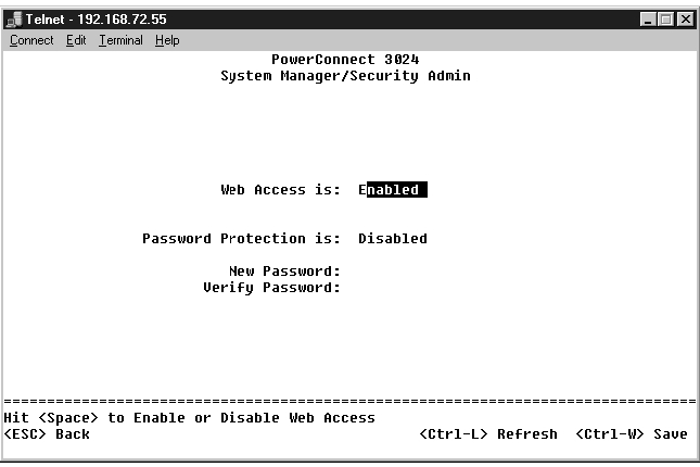
To prevent unauthorized access to the switch, you can turn on password protection.
- Select System Manager and press <Enter>.
Use the <Tab> key to navigate the menu.
- Select Security Admin.
- Type your password and press <Enter>.
- Type your password again to confirm it. Press <Enter>.
- Press <Ctrl><w> to save your changes.
|
NOTE: If you enable password protection without setting your own
password, the default password is switch. The user name is always
root.
|
Before you can assign an IP address to the switch, you must obtain the following information from your network administrator:
- IP address for the switch
- default gateway for the network
- network mask for this network
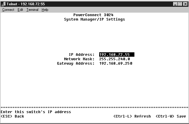
To assign an IP address to the switch, complete the following steps:
- From the Main Menu, select System Manager. Press <Enter>.
- Select IP Settings.
- In the first field, type the correct IP address for this system.
- In the second field, enter the network mask for this network.
- In the third field, enter the IP address of the default gateway for the
network to which the switch belongs.
- Press <Ctrl><w> to save your changes.
- After making IP changes, you must reboot the system. Press <Esc>
twice to return to the Main Menu.
- Select System Manager and then select Reset to reboot the switch.
|
NOTICE: You must reboot the system from the System Manager/Reset page
for the changes to take effect.
|
- Confirm the reset.
A stacked switch configuration combines between 2 and 6 units into a stack of switches. The units are connected in a daisy-chain architecture using the gigabit stacking ports. The stack can be managed as a single entity through the IP address or serial port of the root unit.
|
NOTICE: If you are using the system in a stand-alone configuration, the
stacking cable supplied with your switch is not used.
|
To create a stack, perform the following steps:
- Perform Password Protection and IP Address Assignment for the root
unit, the first unit of the stack.
- Make sure to unplug the power cords of all the units in the stack.
- Place or mount all units of the stack on top of each other with the root
unit at the bottom of the stack.
- Connect the stacking cable of the root unit to its STACK OUT port on
the back of the unit.
- Connect the stacking cable of the root unit to the STACK IN port of
the second unit in the stack.
|
NOTICE: The STACK IN port of the root unit is always unconnected.
|
- Repeat steps 4 and 5 for each additional unit in the stack. That is,
connect the STACK IN port of each unit to the STACK OUT port of
the previous unit.
|
NOTICE: The STACK OUT port of the last unit in the stack is always
unconnected.
|
- Plug in the power cords of the stack units starting with the unit on the
top and proceed in order, with the root unit being the last unit to be
powered up.
The stack is now operational and can be managed through the root unit.
|
NOTICE: Never unplug a stacking cable while the unit is powered up.
|
Perform the following steps to remove a unit from a stack.
- Disconnect the power cords of all units in the stack.
- Disconnect all devices from the last unit in the stack.
- Disconnect the stacking cable connected to the STACK IN port on the
last unit in the stack.
- Remove the unit from the stack.
- Disconnect the stacking cable connected to the STACK OUT port of
the now last unit in the stack. This stacking cable is no longer used in
the stack.
|
NOTICE: The STACK OUT port of the last unit in the stack is always
unconnected.
|
- Plug in the power cords of the stack units starting with the unit on the
top and proceed in order, with the root unit being the last unit to be
powered up.
The stack is now operational and can be managed through the root unit.
|
NOTICE: Never unplug a stacking cable while the unit is powered up.
|
Perform the following steps to add a unit to a stack.
- Disconnect the power cords of all units in the current stack and the
new unit to be added to the stack.
- Connect the new unit's stacking cable to the STACK OUT port of the
topmost unit in the current stack.
- Place or mount the new unit on the top of the stack.
- Connect the unattached end of the stacking cable described in step 2
to the new unit's STACK IN port.
|
NOTICE: The STACK OUT port of the last unit in the stack is always
unconnected.
|
- Plug in the power cords of the stack units starting with the new unit on
the top and proceed in order, with the root unit being the last unit to
be powered up.
The stack is now operational and can be managed through the root unit.
At this point, you are ready to use appropriate network cabling to connect devices to the switch's RJ-45 connectors.
To connect a device to a GBIC port, do the following:
- Use your cabling requirements to select an appropriate GBIC module
type.
- Insert the GBIC module (sold separately) into the GBIC slot.
- Use the appropriate network cabling to connect a device to the
connectors on the GBIC module.
- Enable the GBIC port in the web or console management interface by
performing the following steps:
Web interface:
- Select Port Manager, then select GBIC.
- To enable the GBIC module, select GBIC for the desired port.
Console interface
- Select Port Manager.
- Place the cursor over the desired port number and press the spacebar to enable the GBIC module.
|
NOTICE: Enabling the GBIC port disables the associated built-in
10/100/1000BASE-T port.
|
Back to Contents Page