Dell™ PowerConnect™ 3024 Systems User's Guide
With web-based management, you can configure the PowerConnect 3024 Fast Ethernet Managed Switch and monitor the system using a web browser.
Most web pages for the switch feature the following buttons:
 |
NOTICE: For changes to persist beyond the current session, you must save the new configuration from the Save Configuration page. |
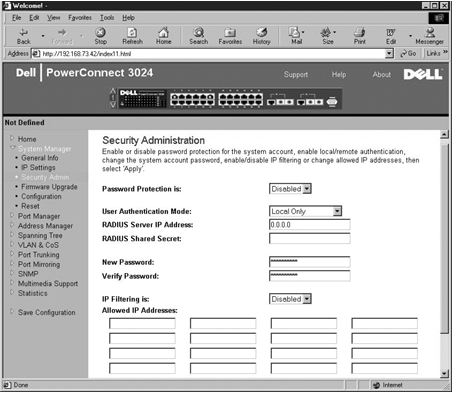
When you connect to the management mode of the switch with a web browser, a login screen is displayed (if password protection has been enabled). The user name is always root. Enter the password to access the switch's management mode.
 |
NOTE: The default password is switch. |
You can manage a stack of up to six units through the web interface. On most pages, you must select the unit in the stack you want to see in the web interface. Where space permits, all six units of the stack are displayed, but only those units that are actually present in the stack are active; the units not used are grayed out.
The following menus are available from the web interface:
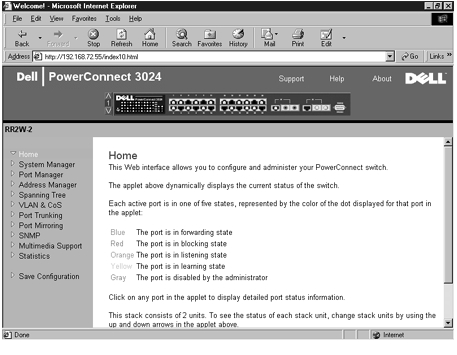
The Home page describes the dynamic switch applet.
|
NOTE: If the system is used in a stack configuration, the arrow keys on the left side of the applet allow you to select a unit in the stack. The dynamic applet will display the status for the selected unit. |
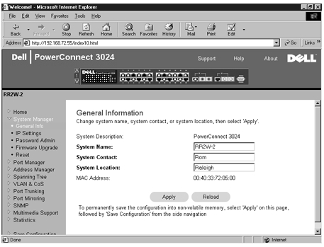
The System Manager page contains all system operations and general information. It includes links to the following options:
The General Info page contains the following information:
It also includes the following editable fields:
To save any changes you make in this page, click Apply. To reset these fields to their current value, click Reload.
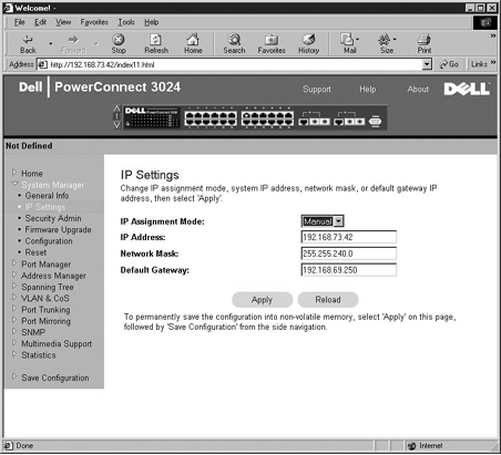
In the IP Settings page, you can manage the IP related information about the system. The page includes the following editable fields:
To save any changes you make in this page for the current session, click Apply. To reset these fields to their current value, click Reload.
For IP address changes to take effect, perform the following steps:
|
NOTE: The default password is switch. |
To save any changes you make in this page, click Apply. To reset these fields to their current value, click Reload.
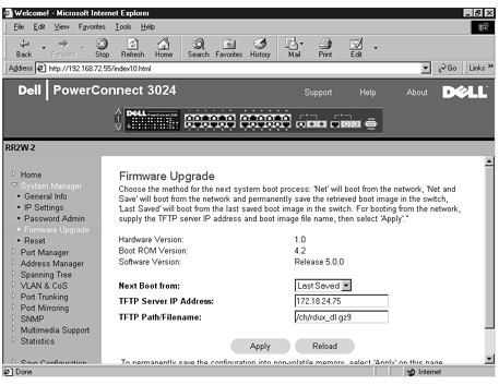
From the Firmware Upgrade page, you can configure the system to download a new version of the management software. You can also set the system to use the new software without overwriting the previous version. See "Software Upgrades" for more information about this process.
The Firmware Upgrade page contains the following information:
It also contains the following editable fields:
|
NOTICE: For changes to persist beyond the current session, you must save the new configuration from the Save Configuration page. You must reboot the system from the System Manager/Reset page to start the firmware upgrade. |
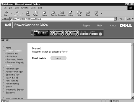
Select Reset to reboot the switch. When prompted, confirm that you want to reset the switch.
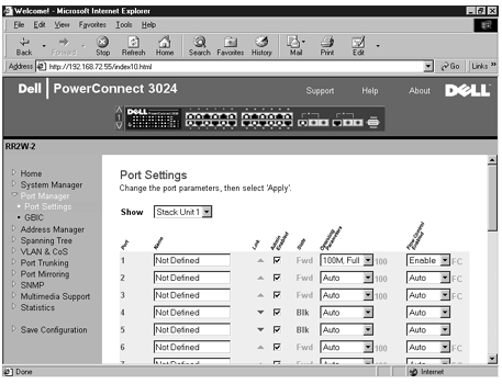
The Port Manager contains links to the following options:
On this page, you can view and edit port parameters. For each port number listed under the Port column, you can change the following parameters listed by column name on the screen:
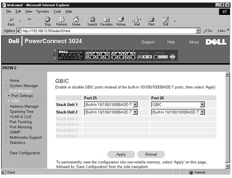
From the GBIC page, you can enable the GBIC slot instead of the built-in 10/100/1000BASE-T port for each of the two Gigabit Ethernet uplinks.
|
NOTICE: Enabling the GBIC port disables the built-in 10/100/1000BASE-T port. |
To save any changes you make in this page for the current session, click Apply. To reset these fields to their current value, click Reload.
The Address Manager page includes links to the following pages:
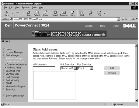
From the Static Addresses page, you can specify the Media Access Control (MAC) address and port number of systems that are to remain available to the switch for an indeterminate amount of time.
The following options are available:
To save any changes you make in this page for the current session, click Apply. To reset these fields to their current value, click Reload.
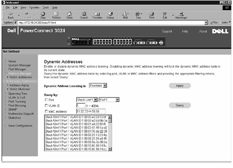
The Dynamic Address lookup table allows you to view the MAC addresses that are currently in the address database. When addresses are in the database, the packets intended for those addresses are forwarded directly to those ports. You can filter out the table by port, VLAN, and MAC address by checking those fields.
Dynamic MAC address learning is enabled by default. This is the standard mode for a network switch. In some networks, the administrator may want to create a secured network by disabling the dynamic address learning capabilities. When this is done, all current dynamic address entries will be locked in. These addresses will not age out and new addresses will not be learned.
In addition, if a new address is detected on a port, the switch will disable the port with the new address, save the current settings to NVRAM, and send out a Simple Network Management Protocol (SNMP) trap warning. This feature is used to block computers that were not on the network before the lockdown from attempting to access the network. Once a port is automatically disabled, the administrator can reenable the port manually. The NVRAM will only be saved the first time a given port detects a new address. The aging time should be raised before disabling the dynamic address learning to provide enough time for the switch to learn all current MAC addresses without the possibility of aging out.
This page contains the following options by which to query the dynamic MAC address table:
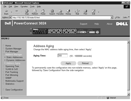
In the Address Aging page, you can specify how long an address stays available to the switch if it is not configured as static.
The following option is available:
To save any changes you make in this page, click Apply. To reset these fields to their current value, click Reload.
The Spanning Tree page contains links to the following pages that allow you to specify the parameters of the spanning tree protocol:
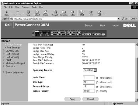
From the Bridge Settings page, you can enable and configure the Spanning Tree. The following options are available:
To save any changes you make in this page for the current session, click Apply. To reset these fields to their current value, click Reload.
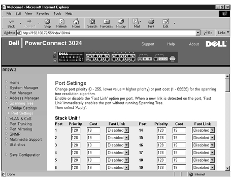
In the Port Settings page, you can specify spanning tree parameters for each port. This page is in a table format. For each port number listed under the Port column, the following fields are available:
|
NOTE: This option is useful if a device is connected to a port that requires network access immediately when the link comes up and cannot wait for a Spanning Tree resolution. |
The VLAN & CoS page includes links to the following pages:
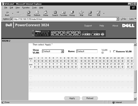
In the Membership page, you define VLAN groups. The following options are available:
The VLAN tagging option is a standard set by the IEEE to facilitate the spanning of VLANs across multiple switches. For more information, see the "Appendix" and IEEE Std 802.1Q-1998 Virtual Bridged Local Area Networks.
To save any changes you make in this page, click Apply. To reset these fields to their current value, click Reload.
The following tasks can be completed from this page:
See the procedure "Add VLAN Membership" later in this section for more information.
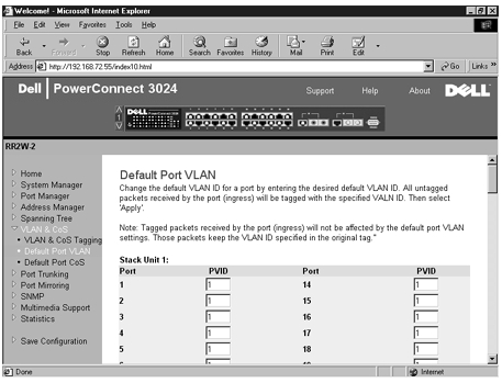
In the Default Port VLAN page, you can specify the default port VLAN ID (PVID) for each port on your switch. All untagged packets entering the switch are tagged by default with the ID specified by the port's PVID.
This page is set up in a table format. For each port listed in the Port column, you can type a PVID in the PVID column.
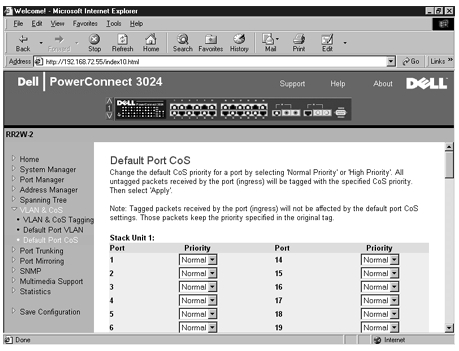
Port Priority allows the user to specify which ports have greater precedence in situations where traffic may be buffered in the switch due to congestion. The ports with a setting of "high" will transmit their packets before those with a "normal" setting. The settings on this page only affect ingress packets that are not already tagged for priority. To raise the priority of a given port, switch the port's setting from "normal" to "high." The default and normal setting for a port is "normal."
In the Default Port CoS page, you can specify the priority for each port on your switch.
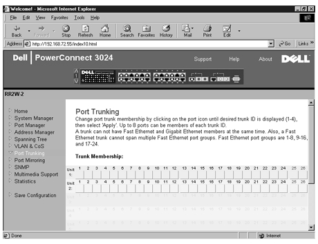
In the Port Trunking page, you can create multiple links between switches that work as one virtual, aggregate link. You can create four trunks at a time, with each trunk containing up to eight ports. Only ports of the same speed can belong to a single trunk: 10/100 Fast Ethernet ports and Gigabit Ethernet ports cannot be in the same trunk.
|
NOTICE: Fast Ethernet trunks can only include ports from a single eight-port cluster: Ports 1 to 8, ports 9 to 16, or ports 17 to 24. |
|
NOTICE: Built-in 10/100/1000BASE-T ports cannot be trunked with GBIC ports. |
To add a port to a trunk, click the toggle button below the port number until the correct trunk number appears.
|
NOTICE: All ports participating in a trunk must be operating in Full Duplex mode. |
|
NOTICE: All ports participating in a trunk should have the same VLAN and CoS settings. |
To save any changes you make in this page, click Apply. To reset these fields to their current value, click Reload.
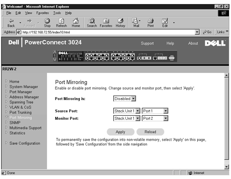
From the Port Mirroring page, you can enable or disable port mirroring. You can also set the source port and monitor ports. Port mirroring helps you debug a network.
The following options are available:
To save any changes you make in this page for the current session, click Apply. To reset these fields to their current value, click Reload.
The SNMP menu contains links to the following pages:
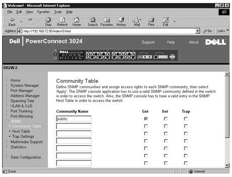
In the Community Table page, you can create different communities and customize access. The public string has Get privileges by default.
The following options are available:
To save any changes you make in this page, click Apply. To reset these fields to their current value, click Reload.
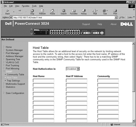
From the SNMP Host Table page, you can add and remove hosts from access rights that have been granted to community groups. The permissions GET, SET, and TRAP are assigned to a community name and then these permissions are assigned to individual machines by adding those machines and their IP address to the appropriate community string. Host authorization can be enabled or disabled.
If the host authorization is disabled (the default setting), the switch allows any SNMP manager to access the switch. If the host authorization is enabled, the administrator can specify up to 16 SNMP managers on the host table that can access the switch.
You must enable host authorization before you can use the host table. Host authorization is a security feature to limit people who are not listed in the host table from accessing the switch.
Once you have enabled host authorization, you must add the host to this table through the console port connection. Otherwise, the switch cannot access the end station using SNMP.
The following fields are available:
|
NOTE: The community name specified here must exist in the switch's SNMP Community Table. |
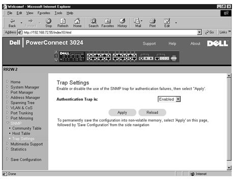
The SNMP Trap Setting allows for the setup of authentication traps.
Authentication traps can be enabled or disabled:
All hosts in community strings with trap privileges are notified when a trap condition occurs.
There are two settings available from this page: IGMP and High Priority Optimization.
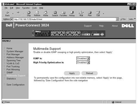
With IGMP (Internet Group Management Protocol) Snooping, you can configure the switch to forward multicast traffic intelligently. Based on the IGMP query and report messages, the switch forwards traffic only to the ports that request multicast traffic. This prevents the switch from broadcasting the traffic to all ports and possibly disrupting network performance.
|
NOTE: IGMP requires a router that learns about the presence of multicast groups on its subnets and keeps track of group membership. |
The IGMP option can be set as follows:
|
NOTICE: Enabling high-priority optimization can effectively disable flow- control for normal-priority packets. |
The High-Priority Optimization setting implements a priority-based head-of-line blocking prevention algorithm in the system. This algorithm ensures that in the case of traffic congestion, normal priority packets do not hold up high priority packets.
|
NOTE: Enabling high priority optimization can improve overall system performance for networks with time-sensitive, prioritized traffic, for example, the traffic associated with multimedia streaming, teleconferencing, or telephony applications. |
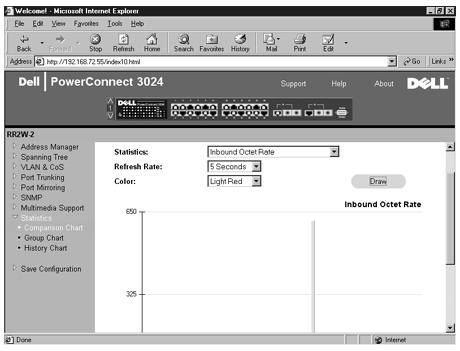
From the Statistics page, you can chart a variety of system data. You can see the value of each bar or line in the chart by clicking on the bar. For each chart, after you have set all the variables, click Draw.
|
NOTE: Rates are displayed as counts per second. Counters are cumulative from the last time the system was booted. |
The following sections describe each type of chart.
The Comparison Chart compares one type of statistic across all of the ports. You must define the following variables:
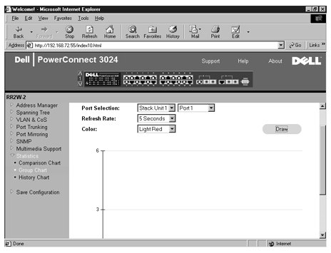
The Group Chart shows all the statistic types for one port. You must define the following variables:
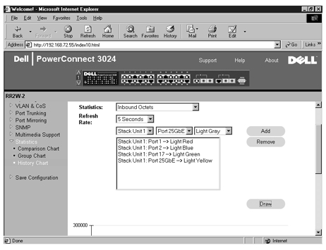
The History Chart charts one type of statistic for any combination of ports. The chart presents data across a set time period so that you can monitor fluctuations over time.
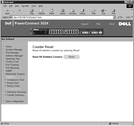
The Counter Reset page allows you to reset all statistics counters.
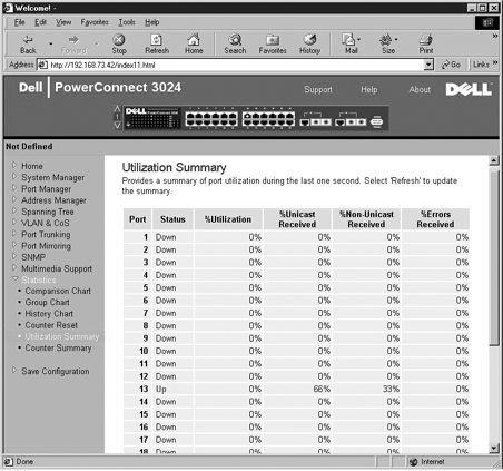
The Utilization Summary page allows you to view (by port) the link status; percent utilization; and ratios of incoming unicast, nonunicast, and error packets.
Click the Refresh button to refresh the Utilization Summary page.
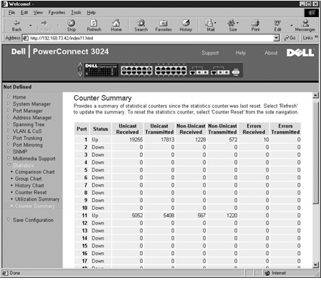
The Counter Summary page allows you to view all ports accumulated, transmitted, and received unicast, nonunicast, and error packets.
Click the Refresh button to refresh the Counter Summary page.
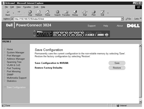
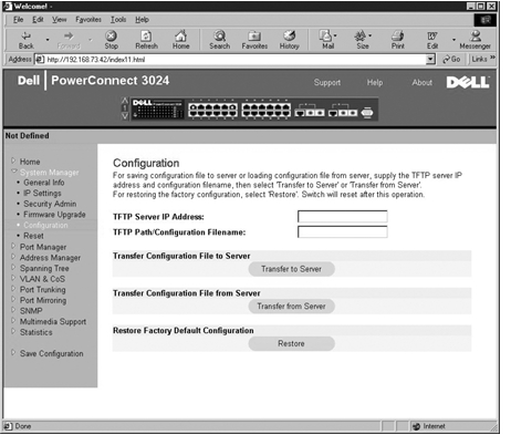
If you make any changes to the system through the Web interface, you must save the changes in the Save Configuration page.
The following options are available:
|
NOTE: Network IP settings like IP address, gateway address, and network mask are not restored by this command. |