Back to Contents Page
Configuring Switch Information
Dell™ PowerConnect™ 3324/3348
User's Guide
 Configuring Network Security
 Configuring Ports
 Configuring Address Tables
 Configuring GARP
 Configuring the Spanning Tree Protocol
 Configuring VLANs
 Aggregating Ports
 Multicast Forwarding Support
This section provides all system operation and general information for configuring network security, ports, Address tables, GARP, VLANs, Spanning Tree, Port Aggregation, and Multicast Support.
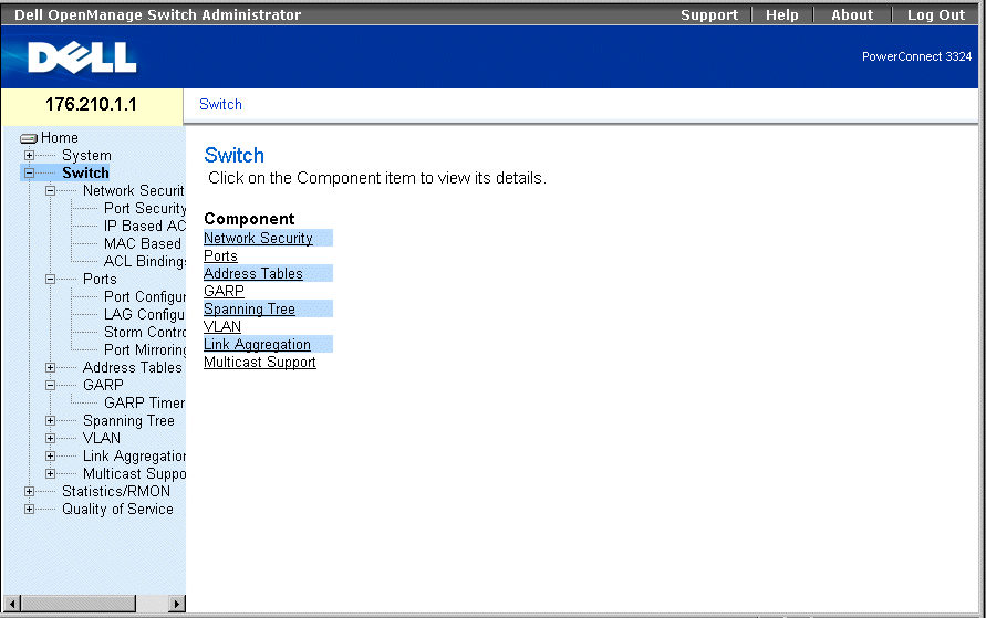
Switch Page
Configuring Network Security
Dell™ PowerConnect™ 3324/3348 allows network managers to set network security through both Access Control Lists and Locked Ports.
To open the Network Security page:
- Select Switch > Network Security. The Network Security page opens.
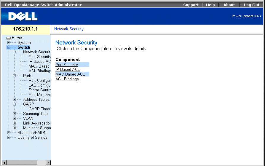
Network Security Page
The Network Security page contains links to the following topics:
Network Security Overview
Access Control Lists (ACLs) allow network managers to define classification actions and rules for specific ingress ports. ACLs contain multiple classification rules and actions. Each classification rule and action is an Access Control Element (ACE). ACEs are the filters that determine traffic classifications. Packets are matched by the following ACEs:
- Protocol
- Destination Port
- Source IP Address
- Destination IP Address
- Wild Card Masks
- Match DSCP
- Match IP-Precedence
- Source MAC Address
- Destination MAC Address
- VLAN ID
For example, a network administrator may define an ACL rule that states that port number 20 can receive TCP packets; however, if a UDP packet is received, the packet is dropped.
A single ACL can contain more than one ACE. The ACEs within an ACL are applied in a first fit manner. The ACEs are processed sequentially, starting with the first ACE. When a packet is matched to an ACE classification, the ACE action is taken, and the ACL processing stops. If a match is not found, the packet is dropped as a default action. If several ACLs are to be processed, the default action is applied only after processing all the ACLs. The default drop action forwards all permitted traffic, including management traffic such as Telnet, HTTP, or SNMP, to the switch.
Network mangers can define two types of ACLs:
- IP ACL—Applies only to IP packets. All classification fields are related to IP packets.
- MAC ACL—Applies to any packet, including non-IP. Classification fields are based on L2 fields only.
Packets entering an ingress port with an active ACL are:
- Forwarded.
- Discarded and a trap is sent.
- Discarded, a trap is sent, and the ingress port is disabled.
PowerConnect 3324/3348 supports up to 128 ACLs. PowerConnect 3324/3348 supports up to 248 ACEs per FE port and up to 120 ACEs per GE port can be defined.
Configuring Port Security
Network users can be limited to specific ports or LAGs with Locked Ports. Locked Port is restricted to users with specific MAC addresses. Locked ports can only be enabled on static MAC addresses. In addition, the Locked Port security option enables storing a list of MAC addresses in the Configuration file. The MAC address list can be restored after the device has been reset. MAC addresses are learned either dynamically or statically.
Packets arriving at a locked port are either forwarded, dropped, or the packet is dropped, a trap is sent, and the ingress port is disabled. Disabled ports are activated from the Port Parameters page. See "Defining Port Parameters". To open the Port Security page:
- Select Switch > Network Security > Port Security. The Port Security page opens.
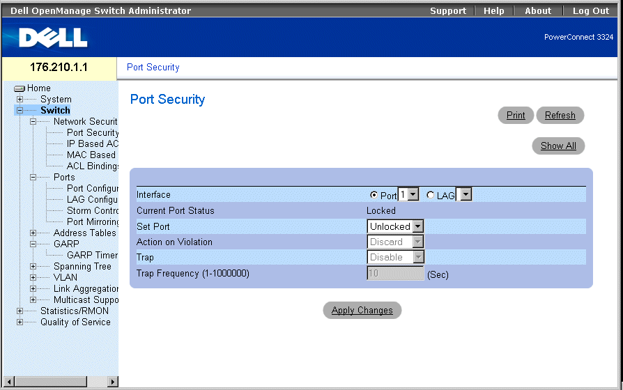
Port Security Page
The Port Security page contains the following fields:
- Interface—Indicates the selected interface type on which locked port is enabled.
- Port—Indicates the selected interface type is a port.
- LAG—Indicates the selected interface type is a stack member.
- Current Port Status—Indicates the current port status.
- Set Port—Indicates that the port is either locked or unlocked. The possible field values are:
- Unlocked—Unlocks Port. This is the default value.
- Locked—Locks Port.
- Action on Violation—Indicates the action to be applied to packets arriving on a locked port. The possible field values are:
- Forward—Forwards the packets from an unknown source; however, the MAC address is not learned.
- Discard—Discards the packets from any unlearned source. This is the default value.
- Shutdown—Discards the packet from any unlearned source and locks the port. Ports remain locked until activated or the device is reset.
- Trap—Enables sending a trap. The possible field values are:
- Enable—Enables traps being sent when a packet is received on a locked port.
- Disable—Disables traps being sent when a packet is received on a locked port. This is the default value.
- Trap Frequency (1-1000000)—Indicates the amount of time (in seconds) between traps. This field only applies to locked ports. The default value is 10 seconds.
Defining a Locked Port:
- Open the Port Security page.
- Select an interface type and number.
- Define the Set Port, Action on Violation, and Trap fields.
- Click Apply Changes. The locked port is added to the Port Security Table, and the
device is updated.
Displaying the Locked Port Table:
- Open the Port Security page.
- Click Show All. The Port Security Table page opens. The fields in the Port Security
Table are the same as the fields in the Port Security page. Locked Ports can also be
defined from the Locked Ports Table as well as the Port Security page.
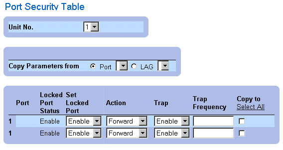
Port Security Table Page
In addition to the fields displayed in the Port Security Page, the Port Security Table page contains the following additional field:
- Unit No.—Indicates the unit number for which the port security information is displayed.
Configuring Locked Port Security with CLI Commands
The following table summarizes the equivalent CLI commands for configuring Locked Port security as displayed in the Port Security Page.
|
CLI Command
|
Description
|
|---|
shutdown | Disables interfaces. |
set interface active {ethernet interface | port-channel port-channel-number} | Reactivates an interface that is shutdown due to port security reasons. |
port security <options> trap frequency | Locks learning of new addresses on an interface. |
show ports security | Displays port lock status. |
The following is an example of the CLI commands:
From 18.1.16 Console # show ports security
Port Action Trap Frequency Counter
---------------------------------------------
5/7 Discard Enable 100 88
7/8 Discard Disable
Defining IP-Based ACLs
The Add ACE to IP Based ACL page allows network administrators to define IP-based Access Control Lists (ACLs) and Access Control Entries (ACEs). ACEs act as filters to match packets to forwarding criteria. To open the Add ACE to IP Based ACL page:
- Select Switch > Network Security > IP based ACL. The Add ACE to IP Based ACL page opens.
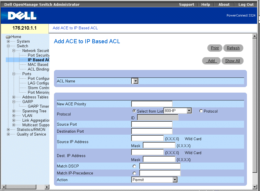
Add ACE to IP Based ACL Page
The Add ACE to IP Based ACL page contains the following fields:
- ACL Name—Contains a list of user-defined ACLs.
- New ACE Priority—Defines the ACE priority. ACEs are checked on the first fit basis. The ACE priority defines the ACE order in the ACL list.
- Protocol—Enables creating an ACE based on a specific protocol.
- Source Port—Indicates the source port that is matched packets. Enabled only when TCP or UDP are selected in the Protocol list.
- Destination Port—Indicates the destination port that is matched packets. Enabled only when TCP or UDP are selected in the Protocol list.
- Source IP Address—Matches the source IP address to which packets are addressed to the ACE.
- Wild Card Mask—Indicates the source IP Address wild card mask. Wild cards are used to mask all or part of a source IP Address. Wild card masks specify which bits are used and which bits are ignored. A wild card mask of 255.255.255.255 indicates that no bit is important. A wildcard of 00.00.00.00 indicates that all bits are important. For example, if the source IP address 149.36.184.198 and the wildcard mask is 255.36.184.00, the first two bits of the IP address are ignored, while the last two bits are used.
- Dest. IP Address—Matches the destination IP address to which packets are addressed to the ACE.
- Wild Card Mask—Indicates the destination IP Address wild card mask. Wild cards are used to mask all or part of a destination IP Address. Wild card masks specify which bits are used and which bits are ignored. A wild card mask of 255.255.255.255 indicates that no bit is important. A wildcard of 00.00.00.00 indicates that all bits are important. For example, if the destination IP address 149.36.184.198 and the wildcard mask is 255.36.184.00, the first two bits of the IP address are used, while the last two bits are ignored.
- Match DSCP—Matches the packet DSCP value to the ACE. Either the DSCP value or the IP Precedence value is used to match packets to ACEs.
- Match IP-Precedence—Matches the packet IP Precedence value to the ACE. Either the DSCP value or the IP Precedence value is used to match packets to ACEs.
- Action—Indicates the ACE forwarding action. The possible field values are:
- Permit—Forwards packets which meet the ACE criteria.
- Deny—Drops packets which meet the ACE criteria.
- Deny and Disable Port—Drops packet that meet the ACE criteria, and disables the port to which the packet was addressed. Ports are reactivated from the Port Configuration; see "Defining Port Parameters".
Adding IP-based ACLs:
- Open the Add ACE to IP Based ACL page.
- Click Add. The Add ACE to IP Based ACL page opens.
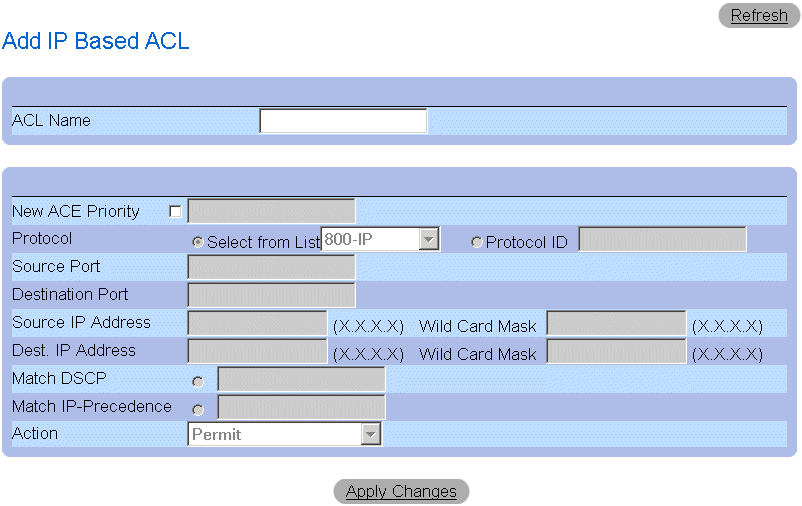
Add IP Based ACL Page
- Define the ACL Name, New Ace Priority, Protocol, Source and Destination Port,
Source and Destination IP Address, Match DSCP or Match IP Precedence, and
Action fields.
- Click Apply Changes. The IP-based ACLs are defined. If a new ACE priority was
defined, it is added to the new ACL.
Assigning ACEs to a IP-based ACL:
- Open the Add ACE to IP Based ACL page.
- Select an ACL in the ACL Name drop-down list.
- Define the New ACE Priority field.
- Define the ACE No., Protocol, Source and Destination Port, Source and Destination
IP Address, Match DSCP or Match IP Precedence, and/or Action fields.
- Click Apply Changes. The ACE is assigned to the IP-based ACL.
Displaying ACL-specific ACEs:
- Open the Add ACE to IP Based ACL page.
- Click Show All. The ACEs Associated with IP-ACL page opens.

ACEs Associated with IP-ACL
Modifying an IP-based ACE:
- Open the Add ACE to IP Based ACL page.
- Click Show All.The ACEs Associated with IP-ACL page opens.
- Modify the ACL Name, New Ace Priority, Protocol, Source and Destination Port,
Source and Destination IP Address, Match DSCP or Match IP Precedence, and
Action fields.
- Click Apply Changes. The IP-based ACEs is modified, and the device is updated.
Removing ACLs:
- Open the Add ACE to IP Based ACL page.
- Click Show All.The ACEs Associated with IP-ACL page opens.
- Select an ACL.
- Check the Remove ACL check box.
- Click Apply Changes. The IP-based ACL is removed, and the device is updated.
Removing ACEs:
- Open the Add ACE to IP Based ACL page.
- Click Show All.The ACEs Associated with IP-ACL page opens.
- Select an ACE.
- Check the Remove check box.
- Click Apply Changes. The IP-based ACE is removed, and the device is updated.
Assigning IP-based ACEs to ACLs Using the CLI Commands
The following table summarizes the equivalent CLI commands for assigning IP-based ACEs to ACLs as displayed in the Add ACE to IP Based ACL page.
|
CLI Command
|
Description
|
|---|
ip access-list name | Enters to IP-Access list configuration mode. |
permit {any | protocol} {any | {source source-wildcard}} {any | {destination destination-wildcard}} [dscp dscp number | ip-precedence ip-precedence] | Allows traffic if the conditions defined in the permit statement are matched. |
deny [disable-port] {any| protocol} {any | {source source-wildcard}} {any | {destination destination-wildcard}} [dscp dscp number | ip-precedence ip-precedence] | Denies traffic if the conditions defined in the deny statement are matched. |
The following is an example of the CLI commands:
Permit 00:00:bo:11:11:11 0:0:0:0:0:0 any VLAN 4
deny 00:00:bo:11:11:11 0:0:0:0:0:0 any VLAN 4
Defining MAC-Based ACLs
The Add ACE to MAC Based ACL page allows network administrators to define MAC-based Access Control Entry (ACE) and Access Control Lists (ACLs). ACEs act as filters to match packets to forwarding criteria. To open the Add ACE to MAC Based ACL:
- Select Switch > Network Security > MAC Based ACL. The Add ACE to MAC Based ACL page opens.
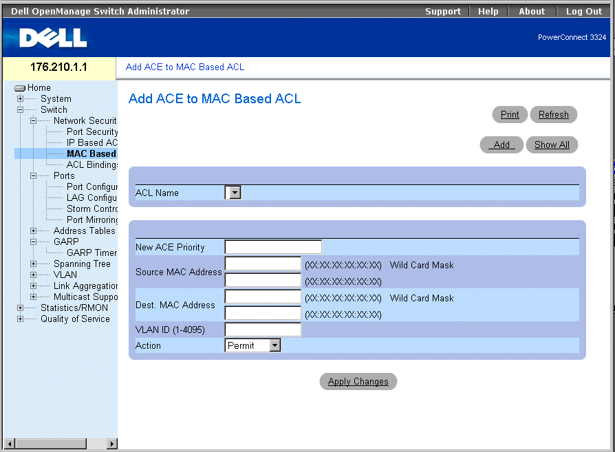
Add ACE to MAC Based ACL Page
The Add ACE to MAC Based ACL page contains the following fields:
- ACL Name—Contains a list of user-defined ACLs.
- New ACE Priority—Enables creating a new ACE and indicates the ACE priority.
- Source MAC Address—Matches the source MAC address from which packets are addressed to the ACE.
- Wild Card Mask—Indicates the source MAC Address wild card mask. Wild cards are used to mask all or part of a source MAC address. Wild card masks specify which bits are used and which are ignored. A wild card mask of FF:FF:FF:FF:FF:FF indicates that no bit is important. A wildcard of 00.00.00.00.00.00.00 indicates that all bits are important. For example, if the source MAC address is E0:3B:4A:C2:CA:E2 and the wildcard mask is 00:3B:4A:C2:CA:FF, the first two bits of the MAC are used, while the last two bits are ignored.
- Destination MAC Address—Matches the destination MAC address to which packets are addressed to the ACE.
- Wild Card Mask—Indicates the destination MAC Address wild card mask. Wild cards are used to mask all or part of a destination MAC address. Wild card masks specify which bits are used and which are ignored. A wild card mask of FF:FF:FF:FF:FF indicates that no bit is important. A wild card mask of 00.00.00.00.00.00 indicates that all bits are important. For example, if the destination MAC address is E0:3B:4A:C2:CA:E2 and the wildcard mask is 00:3B:4A:C2:CA:FF, the first two bits of the MAC are used, while the last two bits are ignored.
- VLAN ID—Matches the packet's VLAN ID to the ACE.
- Action—Indicates the ACE forwarding action. The possible field values are:
- Permit—Forwards packets which meet the ACE criteria.
- Deny—Drops packets which meet the ACE criteria.
- Shutdown—Drops packet that meet the ACE criteria, and disables the port to which the packet was addressed. Ports are reactivated from the Port Configuration, see "Defining Port Parameters".
Adding a MAC-based ACL:
- Open the Add ACE to MAC Based ACL page.
- Click Add. The Add MAC Based ACL page opens.
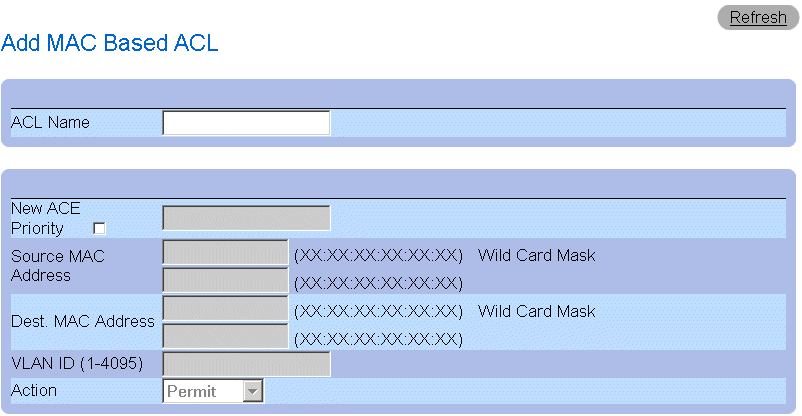
ACEs Associated with Mac-Based ACLs
- Define the ACL Name, Source and Destination Address, and Action fields.
- Click Apply Changes. The MAC-based ACL is defined and the device is updated.
Assigning ACEs to a MAC-based ACL:
- Open the Add ACE to MAC Based ACL page.
- Select an ACL in the ACL Name drop-down list.
- Define the New ACE Priority field.
- Define the ACL Name, VLAN ID, Source and Destination Address, and Action
fields.
- Click Apply Changes. The ACE is assigned to the MAC based ACL.
Displaying ACL-specific ACEs:
- Open the Add ACE to MAC Based ACL page.
- Click Show All. The ACEs Associated with MAC ACL page opens.
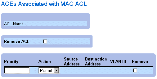
ACEs Associated with MAC ACL
Modifying a MAC-based ACE:
- Open the Add ACE to MAC Based ACL page.
- Click Show All.The ACEs Associated with MAC ACL page opens.
- Modify the ACL Name, Source and Destination Address, and Action fields.
- Click Apply Changes. The MAC-based ACEs is modified, and the device is updated.
Removing ACLs:
- Open the Add ACE to MAC Based ACL page.
- Click Show All. The ACEs Associated with MAC ACL page opens.
- Select an ACL.
- Check the Remove ACL check box.
- Click Apply Changes. The MAC-based ACL is removed, and the device is updated.
Removing ACEs:
- Open the Add ACE to MAC Based ACL page .
- Click Show All.The ACEs Associated with MAC ACL page opens.
- Select an ACE.
- Check the Remove check box.
- Click Apply Changes. The MAC-based ACE is removed, and the device is updated.
Assigning MAC-Based ACEs to ACLs Using the CLI Commands
The following is an example. Station A is connected to port 5, and Station B is connected to port 9. Station A has the MAC address 00-0B-CD-35-6A-00 (ip address: 10.0.0.1 255.255.255.0). Station B has the MAC address 00-06-6B-C7-A1-D8 (ip address: 10.0.0.2 255.255.255.0).
To implement a MAC ACL on port 5 to allow all traffic to move from Station A to Station B, enter the following CLI commands
permit source mac address destination mac address
permit 00-0B-CD-35-6A-00 0.0.0.0.0.0 00-06-6B-C7-A1-D8 0.0.0.0.0.0
All traffic that matches the ACL passes the traffic, and all other traffic is denied. (There is an additional promiscuous deny all entered at the end of the ACL.)
For the above example, Station A is trying to send ICMP ECHO to Station B. The ICMP fails, even if it is permitted by the MAC ACL. The problem is that Station A is trying to send the ICMP ECHO to Station B, but it does not have an entry in the ARP table. Station A tries to get the MAC address of Station B by ARP request that is the broadcast frame with the source MAC of Station A (00-0B-CD-35-6A-00) and destination broadcast (FF.FF.FF.FF.FF.FF). This frame is silently dropped because it does not match the MAC ACL that was set up on port 5.
To solve this issue, the user has to enter the additional permit line that allows the broadcast frame:
permit 00-0B-CD-35-6A-00 0.0.0.0.0.0 FF.FF.FF.FF.FF.FF 0.0.0.0.0.0
 |
NOTE: Even though a user intends to permit traffic from MAC address A to MAC address B,
the user cannot succeed with simple traffic like ICMP, because the additional broadcast is not
taken into consideration.
|
The following table summarizes the equivalent CLI commands for assigning MAC based ACEs to ACLs as displayed in the Add ACE to MAC Based ACL page.
|
CLI Command
|
Description
|
|---|
mac access-list name | Creates Layer 2 MAC ACLs, and enters to MAC-Access list configuration mode. |
permit {any | {host source source-wildcard} any | {destination destination-wildcard}}[vlan vlan-id] | Allows traffic if the conditions defined in the permit statement are matched. |
deny [disable-port] {any | {source source- wildcard} any | {destination destination- wildcard}}[vlan vlan-id] | Allows traffic if the conditions defined in the permit statement are matched. |
The following is an example of the CLI commands:
Console (config)# mac access-list dell
Console (config-mac-al)# permit 6.6.6.6.6.6 0.0.0.0.0.0 any vlan 4
Console (config-mac-al)# deny 6.6.6.6.6.6 0.0.255.255.255.255
Binding ACLs
The ACL Bindings page allows network managers to assign ACL Lists to interfaces. To open the ACL Bindings page:
- Select Switch > Network Security > ACL Bindings. The ACL Bindings page opens.
 |
NOTE: ACLs have no effect unless attached to an interface.
|
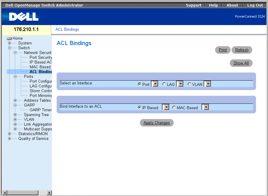
ACL Bindings Page
The ACL Bindings page contains the following fields:
- Select an Interface—Indicates the interface and interface type to which the ACL is attached. The possible field values are:
- Port—Indicates the port number to which the ACL is attached.
- LAG—Indicates the LAG to which the ACL is attached.
- VLAN—Indicates the VLAN to which the ACL is attached.
- Bind Interface to ACL—Indicates the ACL name to which incoming packets are matched. Packets can be matched to either IP-based ACLs or MAC Address based ACLs. The possible field values are:
- IP Based—Indicates that incoming packets are matched to IP-based ACLs.
- MAC Based—Indicates that incoming packets are matched to MAC based ACLs.
Assigning an ACL to an Interface:
- Open the ACL Bindings page.
- Select the ACL type in the Select ACL fields.
- Define the interface to which the ACL is attached in the Attach ACL to an Interface
field.
- Click Apply Changes. The ACL is attached to the interface.
Assigning ACL Membership Using the CLI Commands
The following table summarizes the equivalent CLI commands for assigning ACL membership as displayed in the ACL Bindings page.
|
CLI Command
|
Description
|
|---|
class-map class-map-name [match-all | match-any] | Creates class maps and enters the class-map configuration mode. |
match access-group ACL name | Defines the match criterion to classify traffic. |
show class-map [class-map-name] | Displays all the class maps configured on the device. |
The following is an example of the CLI commands:
Console (config)# class-map class1 match-any
Console (config-cmap)# match access-group dell
Console (config-cmap)# exit
Console (config)# exit
Console # exit
Console> show class-map class1
Class Map match-any class1 (id4)
Configuring Ports
This section provides an explanation and instruction for configuring port functionality including advanced features, such as Storm Control and Port Mirroring. To open the Ports page:
- Select Switch > Ports. The Ports page opens.
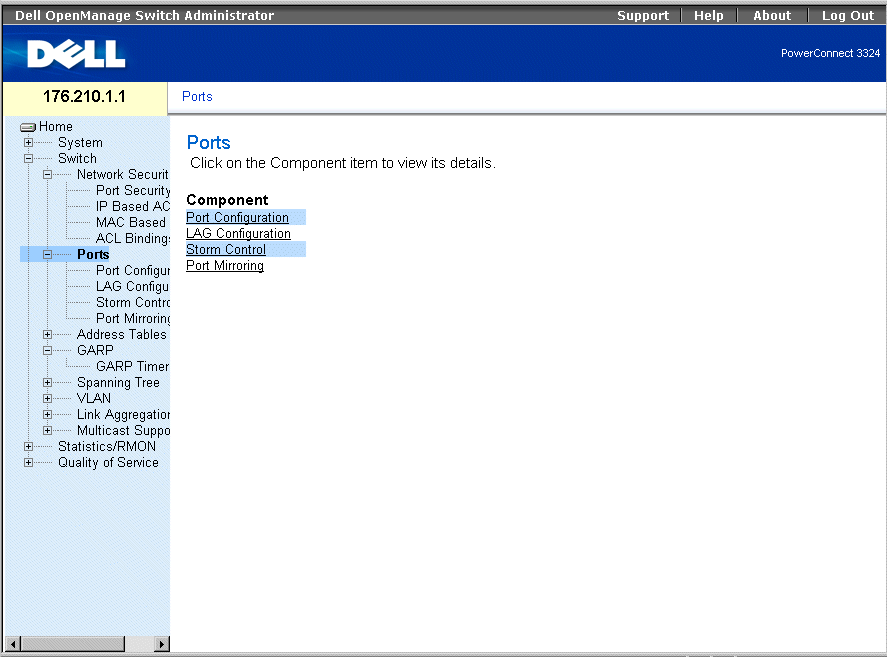
Ports Page
This section includes the following topics:
Defining Port Parameters
The Port Configuration page allows network administrators to define port parameters. To open the Port Configuration page:
- Click Switch > Ports > Port Configuration in the Tree View. The Port Configuration page opens.
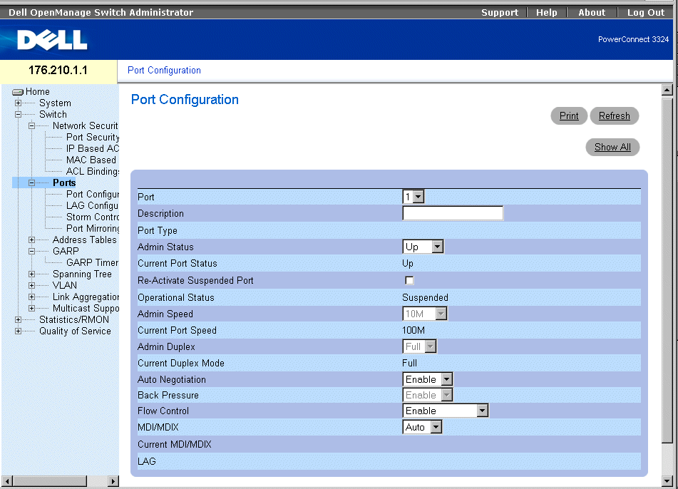
Port Configuration
The Port Configuration page contains the following fields:
- Port—Specifies the port number.
- Description—Provides a brief interface description, for example Ethernet.
- Port Type—Indicates the port type. The possible field values are:
- Ethernet
- Fast Ethernet
- GE
- Admin Status—Controls the selected port traffic. By default, this parameter is set to Enable. The possible field values are:
- Up—Enables traffic forwarding through the port.
- Down—Disables traffic forwarding through the port.
- Current Port Status—Specifies the port operational status. The possible field values are:
- Up—Indicates the port is currently operating.
- Down—Indicates the port is currently non-operational.
- Re-Activate Suspended Port—Reactivates a port if the port has been disabled through the Locked Port or ACL security options.
- Operational Status—Indicates the port operational status.
- Admin Speed—Specifies at what rate the port is running. This value can be specified only if the port is disabled. The possible field values are:
- Current Port Speed—Specifies the synchronized port speed in bps. The possible field values are:
- Admin Duplex—Specifies the synchronized port duplex mode in bps. When Admin Duplex is set to full, Head-of-Line blocking is operational on the selected port. The possible fields values are:
- Full—The interface supports transmission between the device and the client in both directions simultaneously. This is the default value.
- Half—The interface supports transmission between the device and the client in only one direction at a time.
- Current Duplex Mode— Specifies the synchronized port duplex mode. The possible field values are:
- Auto Negotiation—Enables Auto Negotiation on the device. Auto-negotiation is a protocol between two link partners that enables a port to advertise its transmission rate, duplex mode, and flow control abilities to its partner. The possible field values are:
- Enable—Enables auto negotiation on the port.
- Disable—Disables auto negotiation on the port. This is the default value.
- Current Auto Negotiation—Indicates the Auto Negotiation operational status.
- Back Pressure—Enables Back Pressure mode on the device. Back Pressure mode is used with Half Duplex mode to disable ports from receiving messages. When Back Pressure is enabled, Head-of-Line blocking is not operational, even if it is set to enable.
- The possible field values are:
- Enable—Enables back pressure on the port.
- Disable—Disable back pressure on the port. This is the default value.
- Current Back Pressure—Indicates the back pressure operational status.
- Flow Control—Indicates if Flow Control is enabled on the port. Flow control is enabled if the device is in Duplex mode. In addition, when Flow Control is enabled, Head-of-Line is disabled on the selected port. When Flow Control is enabled, Head-of-Line blocking is not operational, even if it is set to enable. The possible field values are:
- Enable—Indicates that Flow Control is enabled on the device.
- Disable—Indicates that Flow Control is disabled on the device. This is the default value.
- Current Flow Control—Indicates the Flow Control operational status.
- Auto-negotiation—Enables auto negotiation of Flow Control on the port.
- Tx Only—Enables auto negotiation for egress ports.
- Rx Only —Enables auto negotiation for ingress ports.
- MDI/MDIX—Allows the device to decipher between crossed and uncrossed cables. Hubs and switches are deliberately wired the opposite way end stations are wired, so that when a hub or switch is connected to an end station, a straight through Ethernet cable can be used, and the pairs match up properly. When two hubs/switches are connected to each other, or two end stations are connected to each other, a crossover cable is used to make sure that the correct pairs are connected. The standard cable wirings are:
- Media Dependent Interface with Crossover (MDIX) for hubs and switches
- Media Dependent Interface (MDI) for end stations
 |
NOTE: Auto MDIX does not operate on FE ports when auto negotiation is disabled.
|
The following table describes the parameter combination settings required to configure ports. These settings ensure that configuration functionalities are maintained.
|
|
Auto Negotiation
|
|---|
|
|
Enabled
|
Disabled
|
|---|
Auto | legal | illegal |
MDI | legal | legal |
MDIX | legal | legal |
- Current MDI/MDIX—Indicates the MDIX operational status. The possible field values are:
- MDI
- MDIX
- Auto—Indicates that the value is set automatically.
- LAG—Specifies if the port is part of a LAG.
Defining Port Parameters:
- Open the Port Configuration page.
- Select a port in the Port field.
- Define the Description, Admin Status, Admin Speed, Admin Duplex, Auto
Negotiation, Back Pressure, Admin Auto MDIX and/or Admin Flow Control fields.
- Click Apply Changes. The port parameters are saved to the device.
Modifying Port Parameters:
- Open the Port Configuration page.
- Select a port in the Port field.
- Modify the Description, Admin Status, Admin Speed, Admin Duplex, Auto
Negotiation, Back Pressure, Admin Auto MDIX and/or Admin Flow Control fields.
- Click Apply Changes. The port parameters are saved to the device.
Displaying the Port Configuration Table:
- Open the Port Configuration page.
- Click Show All. The Port Configuration Table opens.

Ports Configuration Table
In addition to the Port Configuration page fields, the Port Configuration Table also displays the following field:
- Unit Number—Indicates the stacking unit number for which the port information is displayed.
Configuring Ports with CLI Commands
The following examples describe how to set a port to MDIX or MDI mode. To set a port to MDIX mode, enter the following at the system prompt:
console(config-if)# mdix on
The following message displays:
console # show inter config ethernet 1/e1
Flow Admin Back Mdix
Port Type Duplex Speed Neg Control State Pressure Mode
.......................................................
1/e1 100M-Copper Enabled Off Up Disabled On
To set a port to MDI mode, enter the following at the system prompt:
console(config)# inter eth 1/e1
console(config-if)# no mdix
The following message displays:
console # show inter config ethernet 1/e1
Flow Admin Back Mdix
Port Type Duplex Speed Neg Control State Pressure Mode
.......................................................
1/e1 100M-Copper Enabled Off Up Disabled Off
The following table summarizes the equivalent CLI commands for configuring ports as displayed in the Port Configuration.
|
CLI Command
|
Description
|
|---|
interface ethernet interface | Enters the interface configuration mode to configure an ethernet type interface. |
description string | Adds a description to an interface configuration. |
shutdown | Disables interfaces that are part of the currently set context. |
set interface active {ethernet interface | port-channel port-channel-number} | Reactivates an interface that is shut down due to security reasons. |
speed {10 | 100 | 1000} | Configures the speed of a given ethernet interface when not using auto negotiation. |
duplex {half | full} | Configures the full/half duplex operation of a given ethernet interface when not using auto negotiation. |
negotiation | Enables auto negotiation operation for the speed and duplex parameters of a given interface. |
back-pressure | Enables Back Pressure on a given interface. |
flowcontrol {auto | on | off | rx | tx} | Configures the Flow Control on a given interface. |
mdix {on | auto} | Enables automatic crossover on a given interface or Port-channel. |
show interfaces configuration [ethernet interface | port-channel port-channel-number] | Displays the configuration for all configured interfaces. |
show interfaces status [ethernet interface | port-channel port-channel-number] | Displays the status for all configured interfaces. |
show interfaces description [ethernet interface | port-channel port-channel-number] | Displays the description for all configured interfaces. |
The following is an example of the CLI commands:
Console (config)# interface ethernet 1/e5
Console (config-if)#
Console (config-if)# description RD SW#3
Console (config-if)# shutdown
Console (config-if)# no shutdown
Console (config-if)# speed 100
Console (config-if)# duplex full
Console (config-if)# negotiation
Console (config-if)# back-pressure
Console (config-if)# flowcontrol on
Console (config-if)# mdix auto
Console (config-if)# exit
Console (config)# exit
Console# show interfaces configuration
Port Type Duplex Speed Neg Flow Back MDIX Admin
Cont Pres Mode State
---- ---------- ------ ----- ---- ---- ---- ----- -----
1/e1 1g-combo-c Full 1000 Auto On Enable Auto Up
2/e1 100-copper Full 1000 Off Off Disable off Up
2/e2 1g-Fiber Full 1000 Off Off Disable on Up
Neg : Negotiation
Flow Cont: Flow Control
Back Pres: Back Pressure
Console# show interfaces status
Port Port Duplex Speed Neg Flow Back MDI Link
Cont Pres Mode State
---- ---------- ------ ----- ---- ---- ---- ---- -----
2/e1 100-copper Full 1000 off Off Disable Off Down*
Legend
Neg : Negotiation
Flow Cont: Flow Control
Back Pres: Back Pressure
*: The interface was suspended by the system.
Router# show interfaces description
Port Description
---- --------------------------------------------
1/e1 Port that should be used for management only
2/e1
2/e2
Port Channel Description
------------ -----------
1 dell
2 projects
Defining LAG Parameters
The LAG Configuration page allows network managers to configure parameter for configured LAGs. PowerConnect 3324/3348 supports up to 8 ports per LAG, and 6 LAGs per system. The system provides 6 permanent LAGs. For information about Link Aggregated Groups (LAGs) and assigning ports to LAGs, see "Aggregating Ports".
To open the LAG Configuration page:
 |
NOTE: If port configuration is modified while the port is a LAG member, the configuration
change is only effective after the port is removed from the LAG.
|
- Click Switch > Ports > LAG Configuration in the Tree View. The LAG Configuration page displays.
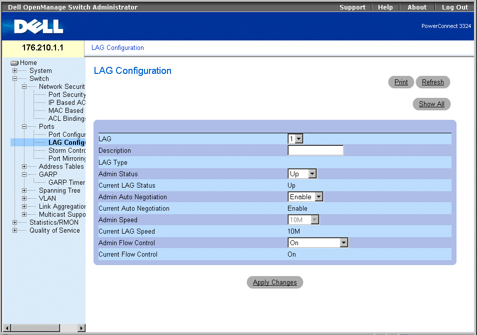
LAG Configuration Page
The LAG Configuration page contains the following fields:
- LAG—Indicates the LAG number.
- Description—Provides a user-defined LAG description.
- LAG Type—Indicates the LAG maximum speed capacity.
- Admin Status—Controls the traffic from the selected LAG. By default, this parameter is set to Up. The possible field values are:
- Up—Enables traffic forwarding through the LAG.
- Down—Disables traffic forwarding through the LAG.
- Current LAG Status—Specifies the LAG status. The possible field values are:
- Up—Indicates the LAG is currently operating.
- Down—Indicates the LAG is currently non-operational.
- Admin Auto Negotiation—Enables Auto Negotiation on the LAG. Auto-negotiation is a protocol between two link partners that enables a LAG to advertise its transmission rate, duplex mode, and flow control (the flow control default is disabled) abilities to its partner. The possible field values are:
- Enable—Enables auto negotiation on the LAG.
- Disable—Disables auto negotiation on the LAG.
- Current Auto Negotiation—Indicates the current Auto Negotiation setting. The possible field values are:
- Admin Speed—Indicates the speed at which the LAG is operating. This value can be entered only if the LAG is disabled. The possible field values are:
- Current LAG Speed—Specifies the synchronized LAG speed in bps. The possible field values are:
- Current Duplex Mode—Specifies the LAG conversation type. The current field values are:
- Full—The interface supports transmission between the device and the client in both directions simultaneously.
- Half—The interface supports transmission between the device and the client in only one direction at a time.
- Admin Current Duplex Mode—Specifies the LAG conversation type. The current field values are:
- Full—The interface supports transmission between the device and the client in both directions simultaneously.
- Half—The interface supports transmission between the device and the client in only one direction at a time.
- Flow Control—Indicates if Flow Control is enabled on the LAG. The possible values are:
- Off—Disables Flow Control on the LAG. This is the default value.
- On—Enables Flow Control on the LAG.
- Auto-negotiation—Enables auto negotiation of Flow Control on the LAG.
- Current Flow Control—Indicates the current Flow Control setting. The possible values are:
Defining LAG parameters:
- Open the LAG Configuration page.
- Select a LAG in the LAG field.
- Define the Description, Admin Status, Port Speed, Admin Auto Negotiation, Admin
Speed, and/or Admin Flow Control fields.
- Click Apply Changes. The LAG parameters are saved to the device.
Modifying LAG parameters:
- Open the LAG Configuration page
- Select a LAG in the LAG field.
- Modify the Description, Admin Status, Port Speed, Admin Auto Negotiation, Admin
Speed, and/or Admin Flow Control fields.
- Click Apply Changes. The LAG parameters are saved to the device.
Displaying the LAG Configuration Table:
- Open the LAG Configuration page.
- Click Show All. The LAG Configuration Table opens.
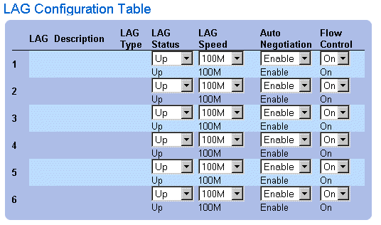
LAG Configuration Table
Configuring LAGs with CLI Commands
The following is an example of how to set up LAG with auto-negotiation disabled, 100Full.
At the system prompt, enter the following to set up static link aggregation:
console> en
console# config
console(config)# interface port-channel 1
console(config-if)# no neg
console(config-if)# speed 100
console(config-if)# exit
console(config)# interface range ethernet 1/e23-24
console(config-if)# no mdix
console(config-if)# no neg
console(config-if)# speed 100
console(config-if)# duplex full
console(config-if)# channel-group 1 mode on
console(config-if)# end
The following message displays:
console# sh interfaces status port-channel 1
Flow Link Back
ch Type Duplex Speed Neg Control State Pressure
..............................................................
ch1 100M Full 100 Disabled Off Up Disabled
The following table summarizes the equivalent CLI commands for configuring LAGs as displayed in the LAG Configuration page.
|
CLI Command
|
Description
|
|---|
interface port-channel port-channel-number | Creates a port-channel and enters port-channel configuration mode. |
channel-group port-channel-number mode {on | auto} | Associates a port with a port-channel. |
show interfaces port-channel [port-channel-number] | Displays Port-channel information (which ports are members of a Port-channel, and whether they are currently active or not). |
The following is an example of the CLI commands:
Console (config)# interface ethernet 1/e5
Console (config-if)# channel-group 1 mode on
Console (config-if)# exit
Console (config-if)# exit
Console # show interfaces port-channel
Channel Port
------------ ----------------------------------
1 Active 1/e5, 2/e2 Inactive 3/e3
2 Active 1/e2
3 Inactive 3/e8
Enabling Storm Control
A Broadcast Storm is a result of an excessive amount of broadcast messages simultaneously transmitted across a network by a single port. Forwarded message responses are loaded onto the network, straining network resources or causing the network to time out.
Storm Control is enabled for all fast Ethernet ports or for Giga ports by defining the packet type and the rate the packets are transmitted. Ports can also be grouped to provide Storm protection for the entire group.
The system measures the incoming Broadcast, Multicast, and Unknown frame rate separately on each port, and discards frames when the rate exceeds a user-defined rate.
The Storm Control page allows network managers to enable and configure Storm Control. To open the Storm Control page :
- Click Switch > Ports > Storm Control in the Tree View to open the Storm Control page.
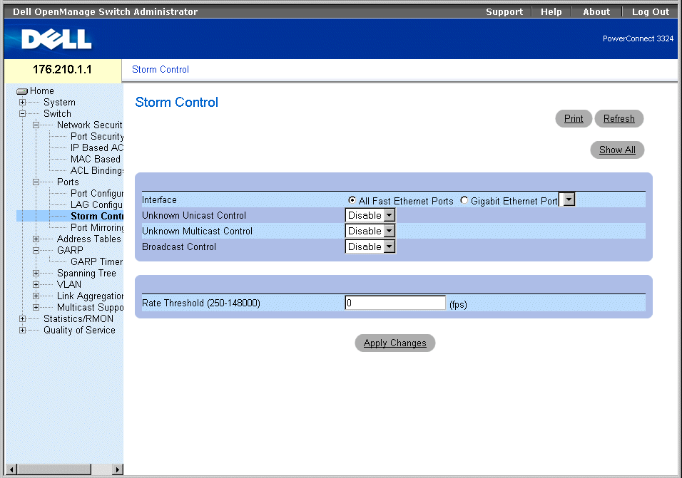
Storm Control Page
The Storm Control page contains the following fields:
- Interface—Indicates the interface on which storm control is being configured.
- All Fast Ethernet Ports—Indicates that storm control is enabled for all FE ports. Storm control can be applied individually to GE ports.
- Gigabit Ethernet Port—Indicates that storm control is enabled for the selected Gigabit Ethernet port. Storm control is either enabled or disabled for ALL FE ports.
- Unknown Unicast Control—Enables moderating unknown Unicast packets on the device. The possible field values are:
- Enable—Enables moderating unknown Unicast packets on the device.
- Disable—Disables moderating unknown Unicast packets on the device.
- Unknown Multicast Control—Enables moderating unknown Multicast packet on the device. The possible field values are:
- Enable—Enables moderating unknown Multicast packets on the device.
- Disable—Disables moderating unknown Multicast packets on the device.
- Broadcast Control—Enables moderating unknown broadcast packets. The possible field values are:
- Enable—Enables moderating Broadcast packets.
- Disable—Disables moderating Broadcast packets.
- Rate Threshold (250-148000)—Sets the broadcast packet rate limit for storm control. For FE ports, the range is 250-148,000. For GE ports the range is 250-262,143 packets. The default for FE ports is 148000, and for GE ports the default is 262,143.
Enabling Storm Control on the device:
- Open the Storm Control page
- Select an interface on which to implement storm control.
- Define the Unknown Unicast Control, Unknown Multicast Control, Broadcast
Control, and the Rate Threshold (250-148000) fields.
- Click Apply Changes. Storm control is enabled on the device.
Modifying Storm Control port parameters:
- Open the Storm Control page.
- Modify the Unknown Unicast Control, Unknown Multicast Control, Broadcast
Control, and the Rate Threshold (250-148000) fields.
- Click Apply Changes. The storm control port parameters are saved to the device.
Displaying the Port Parameters Table:
- Open the Storm Control page .
- Click Show All. The Storm Control Settings Table opens.

Storm Control Settings Table
Configuring Storm Control with CLI Commands
The following table summarizes the equivalent CLI commands for configuring storm control as displayed in the Storm Control page.
|
CLI Command
|
Description
|
|---|
port storm-control enable {unknown | broadcast | multicast} {fastethernet | gigaethernet interface} | Enables broadcast storm control for Unicast, Multicast, and Broadcast packets. |
port storm-control rate gigaethernet interface rate. | Configures the maximum broadcast rate. |
show ports storm-control | Displays the storm control configuration. |
The following is an example of the CLI commands:
Console(config)# port storm-control rate fastethernet 300
Console(config)# port storm-control enable fastethernet
Console# show ports storm-control
Port Unknown Broadcast Multicast Rate
[Packets/sec]
-------------- -------- --------- -------- -----------
Gigaethernet 1 Enabled Disabled Enabled 2000
Gigaethernet 2 Enabled Enabled Enabled 2000
FastEthernet Enabled Enabled Enabled 1000
Defining Port Mirroring Sessions
Port mirroring monitors and mirrors network traffic by forwarding copies of incoming and outgoing packets from one port to a monitoring port. Port mirroring can be used as a diagnostic tool and/or debugging feature. Port mirroring also enables switch performance monitoring.
Network administrators configure port mirroring by selecting a specific port to copy all packets, and different ports from which the packets are copied. Before configuring port mirroring, note the following:
- Monitored ports cannot operate faster than the monitoring ports.
- All the RX/TX packets should be monitored to the same port.
- PowerConnect 3348 mirrors between ports 1-24 and ports 25-48 in the same unit. Mirroring is also possible to and from ports 25-48, and to and from ports 25-48 of a different PowerConnect 3348 or any PowerConnect 3324 port.
- PowerConnect 3348 can mirror to any PowerConnect 3324 unit as long as the source port is not the G2 port. PowerConnect 3348 can mirror to and from another PowerConnect 3348 unit as long as the port is in the PowerConnect 25-48 port range.
The following restrictions apply to ports configured to be destination ports:
- Ports cannot be configured as a source port.
- Ports cannot be a LAG member.
- IP interfaces are not configured on the port.
- GVRP is not enabled on the port.
- The port is not a VLAN member.
- Only one destination port can be defined.
The following restrictions apply to ports configured to be source ports:
- Source ports cannot be a LAG member.
- Ports cannot be configured as a destination port.
- All packets are tagged when they are transmitted from the destination port.
The following restriction applies to ports configured as source ports:
- If any packet is received untagged on the source port, the packet is tagged with the default PVID of the source port when it is sent to the port mirroring destination port.
All the RX/TX packets should be monitored to the same port.
To open the Port Mirroring page:
- Click Switch > Ports > Port Mirroring in the Tree View. The Port Mirroring page opens.
 |
NOTE: When a port is set to be a target port for a port-mirroring session, all normal operations
on this port are suspended. These operations include Spanning Tree and LACP.
|

Port Mirroring Page
- Destination Port—Defines the port number to which port traffic is mirrored. A copy port cannot mirror itself, cannot be a VLAN member other than the source port VLAN, and cannot be configured with an IP interface. All traffic on the source port is tagged.
- Source Port—Defines the port number from which port traffic is copied. A maximum of 8 ports can be mirrored to one mirroring port.
- Type—Specifies the port traffic type that is mirrored. The possible field values are:
- RX—Indicates that incoming traffic is mirrored.
- TX—Indicates that outgoing traffic is mirrored.
- Both—Indicates that both incoming and outgoing traffic is mirrored.
- Status—Indicates the port state. The possible field values are:
- Active—Indicates the port is enabled, and receiving/ forwarding network traffic.
- Not Active—Indicates that the port is disabled, and is not receiving/forwarding network traffic.
- Remove—Removes the port mirroring session. The possible field values are:
- Checked—Removes the port mirroring session.
- Unchecked—Maintains the port mirroring session.
Adding a port mirroring session:
- Open the Port Mirroring page.
- Click Add. The Add Source Port page opens.
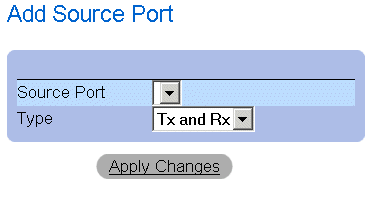
Add Source Port
- Define the Source Port and Type fields.
- Click Apply Changes. The new source port is defined, and the device is updated.
Deleting a copy port from a port mirroring session:
- Open the Port Mirroring page.
- Check the Remove check box.
- Click Apply Changes. The port mirroring session is deleted, and the device is updated.
Configuring a Port Mirroring Session Using CLI Commands
The following table summarizes the equivalent CLI commands for configuring a Port Mirroring session as displayed in the Port Mirroring page.
|
CLI Command
|
Description
|
|---|
port monitor src-interface [rx | tx] | Displays the port copy status. |
show ports monitor | Starts a port monitoring session. |
The following is an example of the CLI commands:
Console(config)# interface ethernet 1/e1
Console(config-if)# port monitor 1/e8
Console# show ports monitor
Source port Destination Port Type Status
----------- ---------------- ----- -------
1/e1 1/e8 RX, TX Active
1/e2 1/e8 RX Active
Configuring Address Tables
MAC addresses are stored in either the Static Address or the Dynamic Address databases. A packet addressed to a destination stored in one of the databases is forwarded immediately to the port. The Static and Dynamic Address Tables can be sorted by interface, VLAN, and interface type. MAC addresses are dynamically learned as packets from sources arrive at the switch. Addresses are associated with ports by learning the ports from the frame's source address. Frames addressed to a destination MAC address that is not associated with any port are flooded to all ports of the relevant VLAN. Static addresses are manually configured by the user. In order to prevent the bridging table from overflowing, dynamic MAC addresses, are erased if they do not experience any traffic after a certain time period.
To open the Address Tables page:
- Click Switch > Address Tables in the Tree View. The Address Tables page opens.
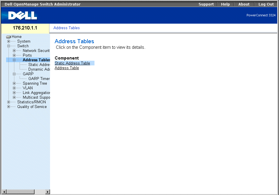
Address Tables Page
The Address Tables page contains links to the following:
Defining Static Addresses
The Static MAC Address page contains a list of static MAC addresses. Static addresses can be added and removed from the Static MAC Address page. In addition, several MAC addresses can be defined for a single port. To open the Static MAC Address page:
- Click Switch > Address Tables > Static Address in the Tree View. The Add Static MAC Address page opens.
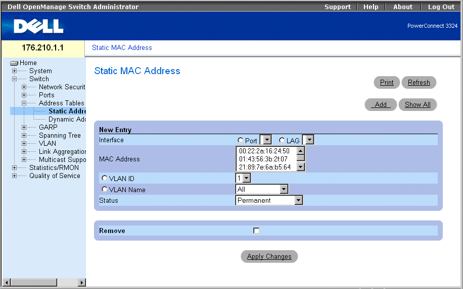
Add Static MAC Address Page
The Add Static MAC Address page contains the following fields:
- Interface—Indicates the specific interface for which a static MAC address is added. The possible field values are:
- Port—Indicates the specific port for which a MAC address is added.
- LAG—Indicates the specific LAG for which a MAC address is added.
- MAC Address—Specifies the MAC address listed in the Current Static Address List.
- VLAN ID—Indicates the value of the VLAN ID attached to the MAC Address.
- VLAN Name—Indicates the user-defined VLAN name.
- Status—Defines the Static MAC address status. The possible field values are:
- Permanent—Indicates the MAC address is permanent.
- Delete on Reset—Indicates the MAC address is deleted when the device is reset.
- Timeout—Indicates the MAC address is deleted when the device times out.
- Secure—Guarantees that a Locked Port MAC address is not deleted. A secure MAC address is deleted from the Port Security Page.
Adding a static address to the Static Address Table:
- Open the Static Address Table.
- Click Add. The Add Static MAC Address page opens.
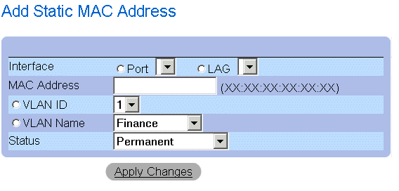
Add Static MAC Address Page
- Define the Interface, MAC Address, VLAN ID or VLAN Name, and the Status fields.
- Click Apply Changes. The new static address is added to the Static Address table, and
the device is updated.
Modifying a static address in the Static Address Table:
- Open the Static Address Table.
- Modify the Port, MAC Address, and the VLAN field.
- Click Apply Changes. The static address is modified, and the device is updated.
Displaying the Static MAC Address Table:
- Open the Static Address Table.
- Click Show All. The Static MAC Address Table opens.
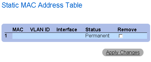
Static MAC Address Table
Removing a static address from the Static Address Table:
- Open the Static Address Table.
- Click Show All to open the Static MAC Address Table.
- Select a single or multiple table entries.
- Check the Remove check box.
- Click Apply Changes. The selected static addresses are deleted, and the device is
updated.
Configuring Static Address Parameters Using CLI Commands
The following table summarizes the equivalent CLI commands for configuring static address parameters as displayed in the Add Static MAC Address page.
|
CLI Command
|
Description
|
|---|
bridge address mac-address {ethernet interface | port-channel port-channel-number} [permanent | delete-on-reset | delete-on-timeout| secure] | Adds a static MAC-layer station source address to the bridge table. |
show bridge address-table static [vlan vlan] [ethernet interface | port-channel port-channel-number] | Displays classes of statically entered entries in the bridge-forwarding database. |
The following is an example of the CLI commands:
Console (config-vlan)# bridge address 168.210.0.10 ethernet 1/e8
permanent
Console# show bridge address table static
Aging time is 300 sec
vlan mac address port type
---- -------------- ----- -----
200 0010.0D48.37FF 5/9 delete-on-reset
Viewing Dynamic Addresses
The Dynamic Address page contains information about querying the Dynamic Address Table, including the interface type, MAC addresses, VLAN, and table sorting. Packets forwarded to an address stored in the Address Table are forwarded directly to those ports. To open the Dynamic Address Page:
- Click Switch > Address Tables > Dynamic Addresses in the Tree View. The Dynamic Address Table Page page opens.
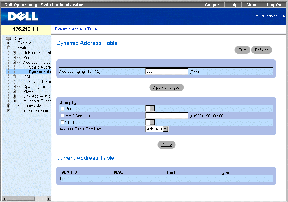
Dynamic Address Table Page
The Dynamic Address page contains the following fields:
- Address Aging—Specifies the amount of time the MAC Address remains in the Dynamic Address Table before it is timed out if no traffic from the source is detected. The default value is 300 seconds.
- Port—Specifies the port numbers for which the table is queried.
- MAC Address—Specifies the MAC address for which the table is queried.
- VLAN ID—Indicates the VLAN ID for which the table is queried.
- Address Table Sort Key—Specifies the method by which the Dynamic Address Table is sorted. The possible field values are:
- Address—Sorts the query results for a designated MAC address.
- VLAN—Sorts the query results by VLAN ID.
- Interface—Sorts the query results by interface, and displays all MAC addresses that have been learned on the designated port.
The Query Results Table contains the following columns:
- VLAN ID—Indicates the VLAN Tag value.
- MAC—Indicates the MAC address.
- Port—Indicate the port that is attached to the dynamic MAC address.
- Type—Indicates the MAC address type.
Redefining the Aging Time:
- Open the Dynamic Address Table.
- Define the Aging Time field.
- Click Apply Changes. The aging time is modified, and the device is updated.
Querying the Dynamic Address Table:
- Open the Dynamic Address Table.
- Define the parameter by which to query the Dynamic Address Table. The Dynamic
Address Table entries can be queried by interface, MAC Address, or VLAN.
- Click Query. The Dynamic Address Table is queried. The query results are sorted by
the selected Address Table Sort Key field value.
Querying and Sorting Dynamic Addresses Using CLI Commands
The following table summarizes the equivalent CLI commands for querying and sorting dynamic addresses as displayed in the Dynamic Address Table page.
|
CLI Command
|
Description
|
|---|
bridge aging-time seconds | Sets the address table aging time. |
show bridge address-table [vlan vlan] [ethernet interface | port-channel port-channel-number] | Displays classes of dynamically created entries in the bridge-forwarding database. |
The following is an example of the CLI commands:
Console (config)# bridge aging-time 250
Console (config)# exit
Console# show bridge address table
Aging time is 250 sec
vlan mac address port type
---- -------------- ----- -----
1 0060.704C.73FF 5/e8 dynamic
1 0060.708C.73FF 5/e8 dynamic
200 0010.0D48.37FF 5/e9 static
Configuring GARP
Generic Attribute Registration Protocol (GARP) protocol is a general-purpose protocol that registers any network connectivity or membership-style information. GARP defines a set of devices interested in a given network attribute, such as VLAN or multicast address. To open the GARP page:
- Click Switch > GARP in the Tree View. The GARP page opens.
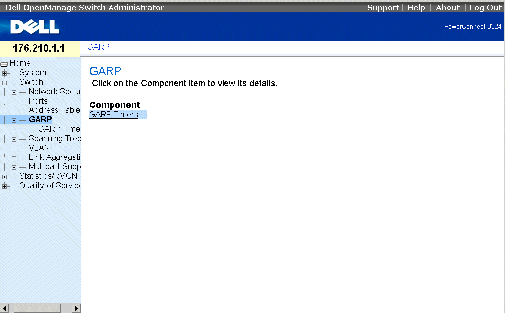
GARP Page
This section includes the following topic:
Defining GARP Timers
The GARP Timers page contains parameters for enabling GARP on the device. To open the GARP Timers page:
- Click Switch > GARP > GARP Timers in the Tree View. The GARP Timers page opens.
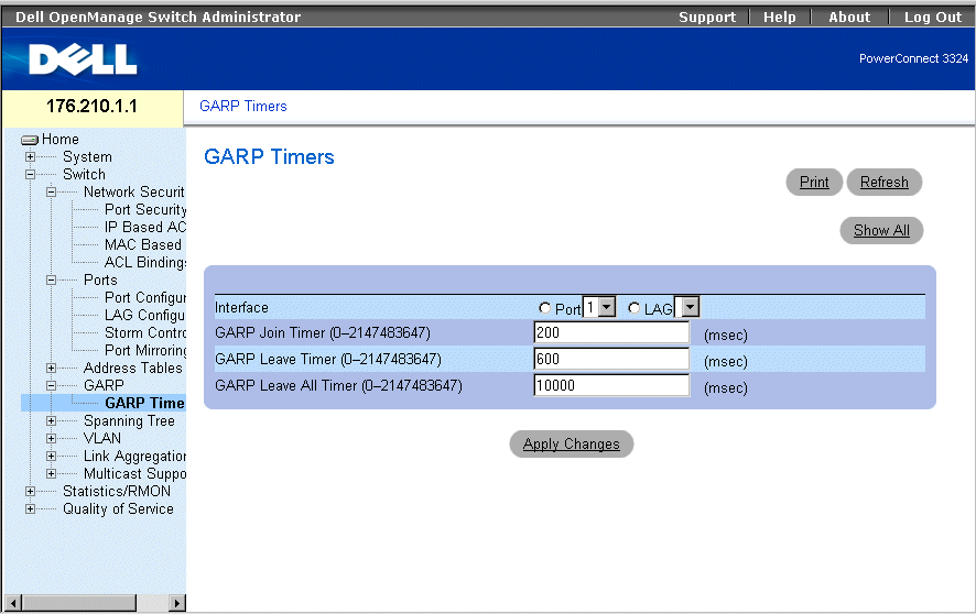
GARP Timers Page
The GARP Timers page contains the following fields:
- Interface—Indicates the type of interface on which GARP Timers are shown. The possible field values are:
- Port—Indicates the port for which GARP Timers are displayed.
- LAG—Indicates the LAG for which GARP Timers are displayed.
- GARP Join Timer (10–2147483647)—Indicates the time in milliseconds that PDUs are transmitted.
- GARP Leave Timer (10–2147483647)—Indicates the time lapse in milliseconds that the device waits before leaving its GARP state. The Leave Time is activated by a Leave All Time message sent/received, and cancelled by the Join message received. The default is 600 milliseconds.
- GARP Leave All Timer (10–2147483647)—Used to confirm the port within the VLAN. The time in milliseconds between messages sent. The default is 10000 milliseconds.
 |
NOTE: The following relationships between the various timer values must be maintained: Leave
time must be greater than or equal to three times the join time. Leave-all time must be greater
than the leave time.
|
Defining GARP Timers:
- Open the GARP Timers page.
- Define the Interface, GARP Join Time, GARP Leave Timer, and GARP Leave All
Timer.
- Click Apply Changes. The GARP parameters are saved to the device.
Displaying the GARP Timers Table:
- Open the GARP Timers page.
- Click Show All. The GARP Timers Table opens.
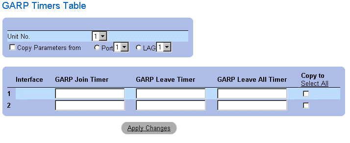
GARP Timers Table
In addition to the GARP Timers page fields, the GARP Timers Table page also displays the following fields:
- Unit No.—Indicates the stacking unit number.
- Copy From—Copies the port GVRP parameters to interfaces specified in the Copy to field.
- Copy To—Indicates the interfaces to which the GVRP Timers are copied.
Copying GARP Information:
- Open the GARP Timers page.
- Click Show All. The GARP Timers Table opens.
- Select an interface in the Copy Parameters from field.
- Select the interfaces to which the GARP Timers information is copied in the Copy To
fields.
Defining GARP Timers Using CLI Commands
The following table summarizes the equivalent CLI commands for defining GARP timers as displayed in the GARP Timers page.
|
CLI Command
|
Description
|
|---|
garp timer {join | leave | leaveall} timer_value | Sets the GARP application join, leave, and leaveall GARP timer values. |
The following is an example of the CLI commands:
Console (config)# interface ethernet 1/e8
Console (config-if)# garp timer leave 900
Configuring the Spanning Tree Protocol
The Spanning Tree Protocol (STP) provides a single path between end stations on a Layer 2 network, thereby eliminating loops.
Loops occur when alternate routes exist between hosts. Loops in an extended network may cause bridges to forward traffic indefinitely, resulting in increased traffic and a reduction in network performance. To open the Spanning Tree page:
- Click Switch > Spanning Tree in the Tree View. The Spanning Tree page opens.
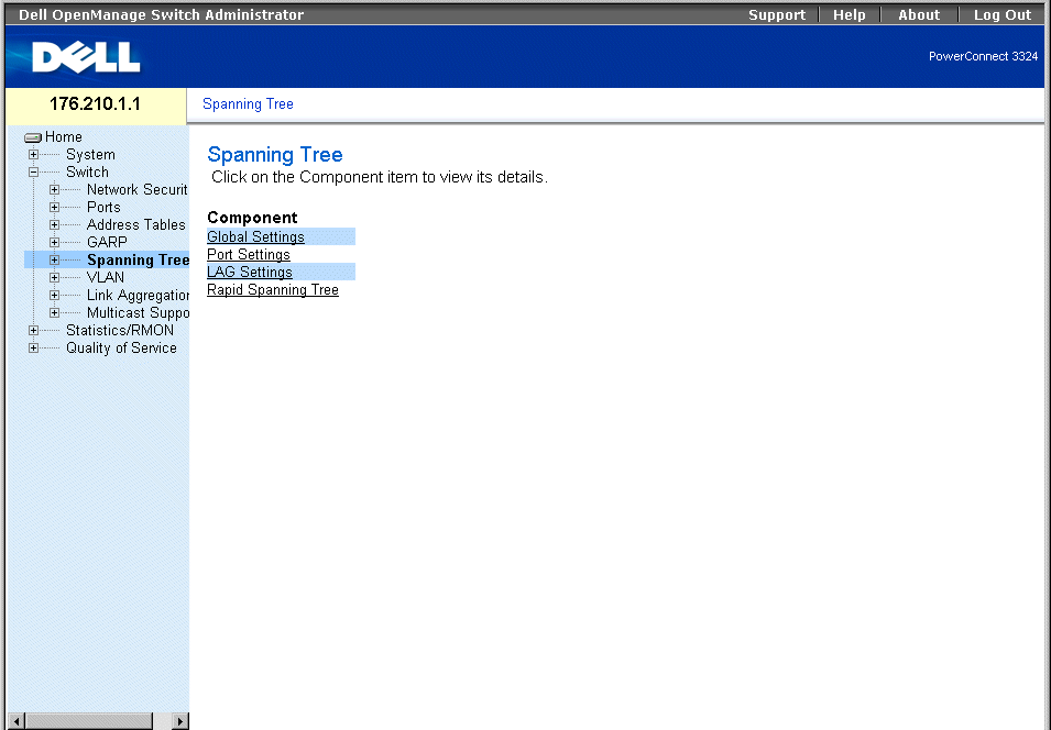
Spanning Tree Page
This section contains the following topics:
Defining STP Global Settings
The Spanning Tree Global Parameters page contains parameters for enabling and configuring STP operation on the device. To open the Spanning Tree Global Parameters page:
- Click Switch > Spanning Tree > Global Settings in the Tree View. The Spanning Tree Global Parameters page opens.

Spanning Tree Global Settings Page
The Spanning Tree Global Parameters page contains the following fields:
- Spanning Tree State—Enables STP on the device. The possible field values are:
- Enable—Enables STP on the device.
- Disable—Disables STP on the device.
- STP Operation Mode—Indicates the STP mode by which STP is enabled on the device. The possible field values are:
- Classic STP—Enables Classic STP on the device (IEEE 802.1D).
- Rapid STP—Enables Rapid STP is enabled on the device (IEEE 802.1w). For more information on Rapid STP, see "Configuring Rapid Spanning Tree".
- Priority (0-65535)—Specifies the bridge priority value. When switches or bridges are running STP, each is assigned a priority. After exchanging BPDUs, the switch with the lowest priority value becomes the Root Bridge. The default value is 32768. The port priority value is incremented in multiples of 16; for example, 16, 32, 64, 80, and so on.
- Hello Time (1-10)—Specifies the switch Hello Time. The Hello Time indicates the amount of time in seconds a root bridge waits between configuration messages. The default is 2 seconds.
- Max Age (6-40)—Specifies the switch Maximum Age Time. The Maximum Age Time indicates the amount of time in seconds a bridge waits before sending configuration messages. The default maximum age time is 20 seconds.
- Forward Delay (4-30)—Specifies the switch forward delay time. The Forward Delay Time indicates the amount of time in seconds a bridge remains in a listening and learning state before forwarding packets. The default is 15 seconds.
- Bridge ID—Identifies the Bridge priority and MAC address.
- Root Bridge ID—Identifies the Root Bridge priority and MAC address.
- Root Port—Indicates the port number that offers the lowest cost path from this bridge to the Root Bridge. It is significant when the Bridge is not the Root. The default is zero.
- Root Path Cost—The cost of the path from this bridge to the root.
- Topology Changes Counts—Specifies the total amount of STP state changes that have occurred.
- Last Topology Change—Indicates the amount of time that has elapsed since the bridge was initialized or reset, and the last topographic change occurred. The time is displayed in a day hour minute second format, for example, 2 days 5 hours 10 minutes and 4 seconds.
Defining STP Global Parameters:
- Open the Spanning Tree Global Parameters page.
- Select Enable in the Spanning Tree State field.
- Select the Classic STP in the STP Operation Mode field.
- Click Apply Changes. STP is enabled on the device.
Modifying STP Global Parameters:
- Open the Spanning Tree Global Parameters page.
- Define the STP Operation Mode, Bridge Priority, Hello Time (Sec), Max Age (Sec),
and the Forward Delay (Sec) fields.
- Click Apply Changes. The STP parameters are modified, and the device is updated.
Defining STP Global Parameters Using CLI Commands
The following table summarizes the equivalent CLI commands for defining STP Global Parameters as displayed in the Spanning Tree Global Settings page.
|
CLI Command
|
Description
|
|---|
spanning-tree | Enables spanning tree functionality. |
spanning-tree mode {stp | rstp} | Configures the spanning tree protocol currently running. |
spanning-tree priority priority | Configures the spanning tree priority. |
spanning-tree hello-time seconds | Configures the spanning tree bridge Hello Time, which is how often the switch broadcasts Hello messages to other switches. |
spanning-tree max-age seconds | Configures the spanning tree bridge maximum age, which determines the amount of time protocol information received on a port is stored by the switch. |
spanning-tree forward-time seconds | Configures the spanning tree bridge forward time, which is the amount of time a port remains in the listening and learning states before entering the forwarding state. |
show spanning-tree [ethernet interface | port-channel port-channel-number] | Displays spanning tree configuration. |
The following is an example of the CLI commands:
Console(config)# spanning-tree
Console(config)# spanning-tree mode rstp
Console(config)# spanning-tree priority 12288
Console(config)# spanning-tree hello-time 5
Console(config)# spanning-tree max-age 10
Console(config)# spanning-tree forward-time 25
Console(config)# exit
Console# show spanning-tree
Spanning tree enabled mode RSTP
Root ID Priority 32768
Address X.X.X.X.X.X
Cost 57
Port 1/e1
Hello Time 2 sec Max Age 20 sec Forward Delay 15 sec
Bridge ID Priority 32769
Address X.X.X.X.X.X
Hello Time 2 sec Max Age 20 sec Forward Delay 15 sec
Number of topology changes 2 last change occurred 00:23:56 ago
Times: hold 1, topology change 35, notification 2
hello 2, max age 20, forward delay 15
Interface Port ID Designated Port ID
Name Prio Cost Sts Cost Bridge ID Prio.Nbr
-------- ------ --- --- -------------------- ------
1/e1 128 19 FWD 38 8000 00:30:94:41:62c1 80 001
1/e2 128 19 FWD 57 8000 00:02:4b:29:7a:00 80 002
ch1 128 19 FWD 57 8000 00:02:4b:29:7a:00 80 003
Defining STP Port Settings
The STP Port Settings page allows network managers to assign STP properties to individual ports. To open the STP Port Settings page:
- Click Switch > Spanning Tree > Port Settings in the Tree View. The STP Port Settings page opens.
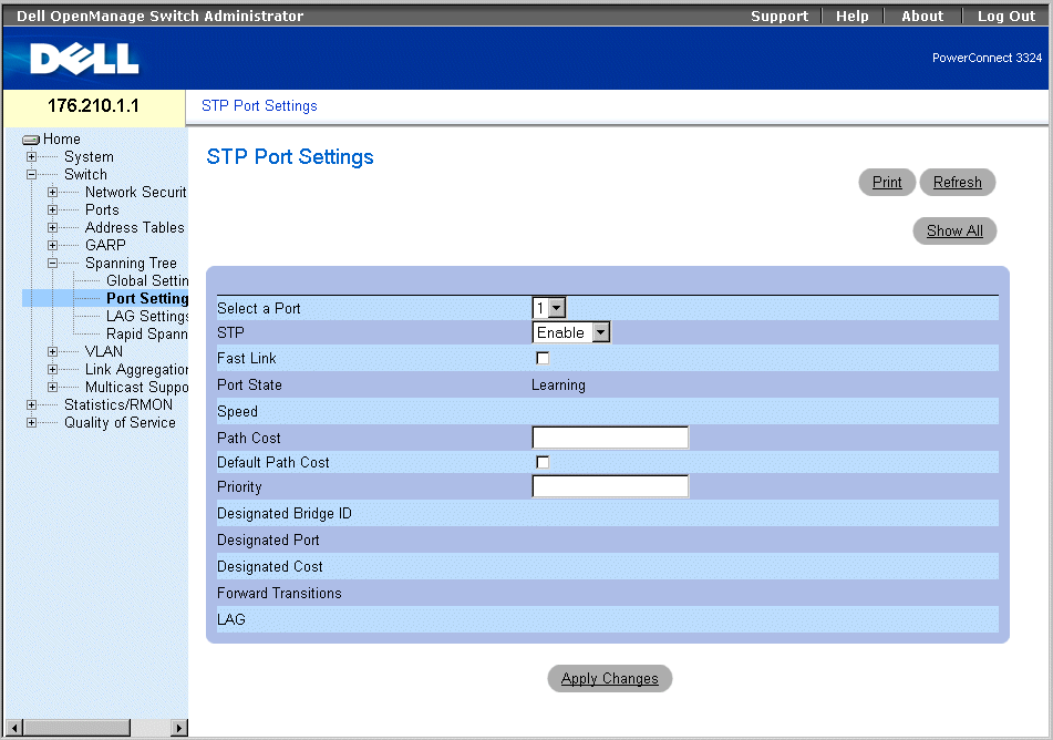
STP Port Settings Page
The STP Port Settings page contains the following fields:
- Select a Port—Indicates the port for which STP statistics are displayed.
- STP—Enables STP on the port. The possible field values are:
- Enable—Enables STP on the port.
- Disable—Disables STP on the port.
- Fast Link—Enables Fast Link mode for the port. If Fast Link mode is enabled for a port, the port is automatically placed in the Forwarding State when the port link is up. Fast Link mode optimizes the time it takes for the STP protocol to converge (STP convergence can take 30-60 seconds in large networks).
- Port State—Indicates the current STP state of a port. If enabled, the Port State determines what forwarding action is taken on traffic. The possible field values are:
- Disabled—Indicates the port link is currently down.
- Blocking—The port is currently blocked and cannot be used to forward traffic or learn MAC addresses.
- Listening—The port is currently in the listening mode. The port cannot forward traffic nor can it learn MAC addresses.
- Learning—The port is currently in the learning mode. The port cannot forward traffic however it can learn new MAC addresses.
- Forwarding—The port is currently in the forwarding mode. The port can forward traffic and learn new MAC addresses.
- Speed—Indicates the port speed. The possible field values are:
- Path Cost—Indicates the amount this port contributes to the Root Path Cost. The Path Cost can be adjusted to a higher or lower value, and can forward traffic to or away from a path being rerouted. The path cost has a value of 1 to 65,535.
- Default Path Cost—Specifies the default path cost.
- Priority—Indicates the priority value of the port. The Priority value can be used to influence the port choice when a bridge has two ports connected in a loop on the same LAN. The priority value is between 0 -255.
- Designated Bridge ID—Indicates the priority and the MAC Address of the designated bridge.
- Designated Port—Indicates the priority and the MAC Address of the selected port on the designated bridge.
- Designated Cost—Indicates the cost of the designated port participating in the STP topology.
- Forward Transitions—Indicates the number of times the port has changed from the blocking state to forwarding.
- LAG—Specifies the LAG to which the port is attached.
Enabling STP on a port:
- Open the STP Port Settings page.
- Select Enabled in the STP field.
- Define the Priority, Path Cost, Default Path Cost, and the Fast Link fields.
- Click Apply Changes. STP is enabled on the port.
Modifying STP Port Properties:
- Open the STP Port Settings page.
- Modify the Priority, Path Cost, Default Path Cost, and the Fast Link fields.
- Click Apply Changes. The STP port parameters are modified, and the device is
updated.

STP Port Table Page
Defining STP Port Parameters Using CLI Commands
The following table summarizes the equivalent CLI commands for defining STP port parameters as displayed in the STP Port Settings page.
|
CLI Command
|
Description
|
|---|
spanning-tree disable | Disables spanning tree on a specific port. |
spanning-tree cost cost | Configures the spanning tree port cost for a port. |
spanning-tree port-priority priority | Configures port priority. |
show spanning-tree [ethernet interface | port-channel port-channel-number] | Displays spanning tree configuration. |
spanning-tree portfast | Enables PortFast mode. |
The following is an example of the CLI commands:
Console(config)# interface ethernet 1/e5
Console(config-if)# spanning-tree disable
Console(config-if)# spanning-tree cost 35000
Console(config-if)# spanning-tree port-priority 96
Console(config-if)# exit
Console(config)# exit
Console# show spanning-tree ethernet 1/e5
Console# show spanning-tree ethernet 1/e5
Interface Port ID Designated Port ID
Name Prio Sts Enb Cost Cost Bridge ID Prio.Nbr
----- ---- --- --- ---- ------------------ --------
1/e5 128 DSBL True 100 0 8000 xx.xx.xx.xx.xx.xx 80 001
Spanning tree enabled
Port Fast: no (configured: no)
Type: point-to-point (configured: auto)
Number of transitions to forwarding state: 1
BPDU: sent 2, received 120638
Defining STP LAG Settings
The STP LAG Settings page allows network managers to assign STP parameters for LAGs. To open the STP LAG Settings page:
- Click Switch > Spanning Tree > LAG Settings in the Tree View. The STP LAG Settings page opens.
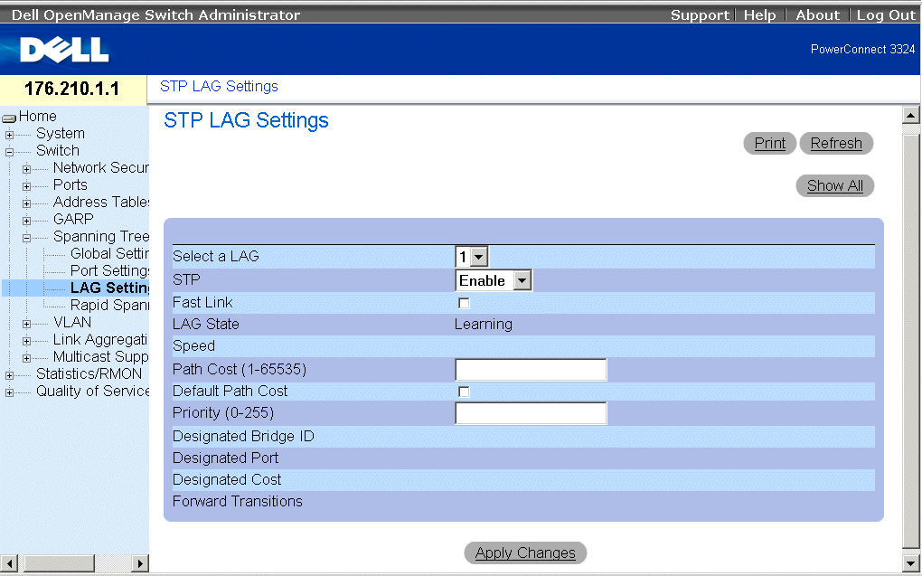
STP LAG Settings Page
The STP LAG Settings page contains the following fields:
- Select a LAG—Indicates the user-defined LAG. For more information on defining LAGs, see "Defining LAG Membership".
- STP—Enables STP on the LAG. The possible field values are:
- Enable—Enables STP on the LAG.
- Disable—Disables STP on the LAG.
- Fast Link—Enables Fast Link for the LAG. If Fast Link is enabled for a LAG, the LAG is automatically placed in the Forwarding State. Fast Link optimizes the time it takes for the STP protocol to converge (STP convergence can take 30-60 seconds in large networks).
 |
NOTE: Use the Fast Link option only in appropriate cases; for example, when the device is a
leaf in the STP network topology for end stations.
|
- LAG State—Indicates the current STP state for a LAG. If enabled, the LAG State determines what forwarding action is taken on traffic. If the bridge discovers a malfunctioning LAG, the LAG is placed in the Disabled state. The possible field values are:
- Disabled—The link is currently down.
- Blocking—The LAG is currently blocked and cannot be used to forward traffic or learn MAC addresses.
- Listening—The LAG is currently in the listening mode. The LAG cannot forward traffic or learn MAC addresses.
- Learning—The LAG is currently in the learning mode. The LAG cannot forward traffic; however, it can learn new MAC addresses.
- Forwarding—The LAG is currently in the forwarding mode. The LAG can forward traffic and learn new MAC addresses.
- Speed—The speed of the ports comprising the LAG.
- Path Cost (1-65535)—Indicates the amount this LAG contributes to the Root Path Cost. The Path Cost can be adjusted to a higher or lower value and can forward traffic to or away from a path being rerouted. The path cost has a value of 1 to 65,535.
- Default Path Cost—Indicates the default path cost. The default path cost for a LAG is 4.
- Priority (0-255)—Indicates the priority value of the LAG. The Priority value can be used to influence the LAG choice when a bridge has two looped ports on the same LAN. The priority value is between 0 -255.
- Designated Bridge ID—Indicates the priority and MAC Address for the designated bridge.
- Designated Port—Indicates the priority and MAC Address for the selected port.
- Designated Cost—Indicates the Designated Cost.
- Forward Transitions—Indicates the number of times the port has changed from the blocking state to forwarding.
Enabling STP on a LAG:
- Open the STP LAG Settings page.
- Select Enable in the STP field.
- Define the Priority, Path Cost, and Fast Link fields.
- Click Apply Changes. STP is enabled on the LAG, and the device is updated.
Modifying the LAG STP parameters:
- Open the STP LAG Settings page.
- Modify the Priority, Path Cost, and Fast Link fields.
- Click Apply Changes. The STP LAG parameters are modified, and the device is
updated.

STP LAG Table Page
Defining STP LAG Parameters Using CLI Commands
The following table summarizes the equivalent CLI commands for defining STP LAG parameters as displayed in the STP LAG Settings page.
|
CLI Command
|
Description
|
|---|
interface port-channel port-channel-number | Enters Port-channel configuration mode.
|
spanning-tree port-priority priority | Configures LAG priority.
|
The following is an example of the CLI commands:
console(config)# interface port-channel 1
console(config-if)# spanning-tree port-priority 16
Configuring Rapid Spanning Tree
The Classic Spanning Tree prevents L2 forwarding loops in a general network topology. However, convergence can take up to 30-60 seconds. The convergence time is considered too long for many applications. When network topology allows, faster convergence may be possible. The Rapid Spanning Tree Protocol (RSTP) detects and uses network topologies that provide faster convergence of the spanning tree without creating forwarding loops.
STP has the following different port states:
- Listening
- Learning
- Blocking
- Forwarding
A listening port is either a designated or a root port, and is in the process of moving to the forwarding state. However, after the port is in the forwarding state, there is no way to determine whether the port is a root or designated port. The RSTP addresses this problem by decoupling the port's role and its state. Use the Spanning Tree Global Settings page to enable RSTP.
To open the Rapid Spanning Tree (RSTP) page:
- Click Switch > Spanning Tree > Rapid Spanning Tree in the Tree View. The Rapid Spanning Tree (RSTP) page opens.
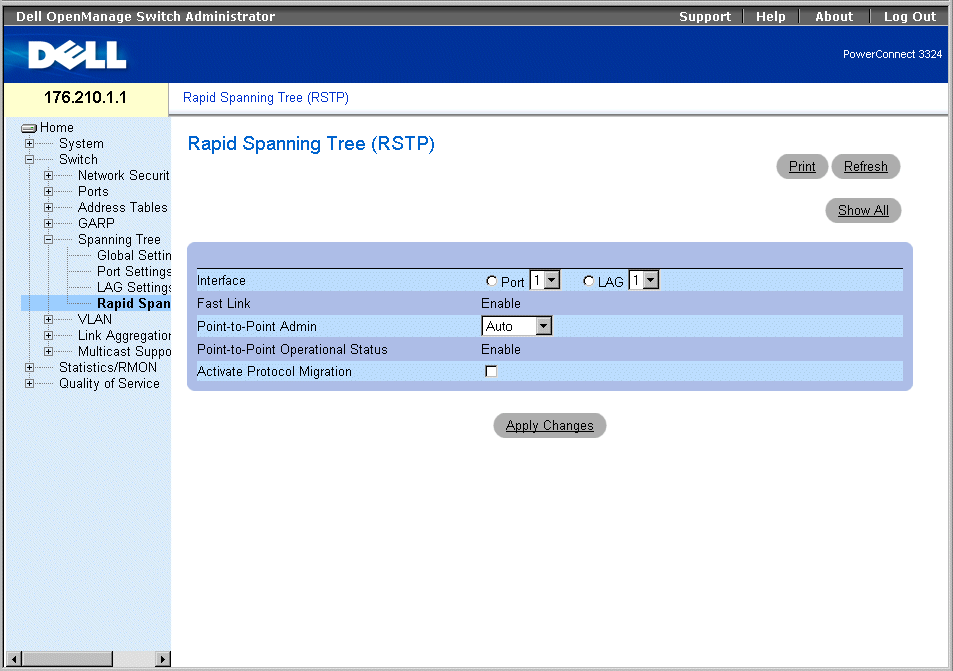
Rapid Spanning Tree (RSTP) Page
The Rapid Spanning Tree (RSTP) page contains the following fields:
- Interface—Indicates the interface number on which RSTP is enabled.
- Fast Link—Indicates if Fast Link is enabled.
- Point-to-Point Admin—Specify the port link type as point-to-point. The possible field values are:
- Auto—Allows the device to automatically detect a point-to-point link.
- Enable—Enables establishing a point-to-point link.
- Disable—Disables establishing a point-to-point link.
- Point-to-Point Operational Status—Indicates the point-to-point operating state.
- Activate Protocol Migration —Activates protocol migration. Protocol migration allows protocols to renegotiate with neighboring switches by testing the ports to see if they can migrate to RSTP. The possible field values are:
- Checked—Activates protocol migration.
- Unchecked—Disables protocol migration.
Enabling Rapid STP:
- Open the Rapid Spanning Tree (RSTP) page.
- Define the Point-to-Point Admin, Protocol Operation, and Activate Protocol
Migration fields.
- Click Apply Changes. The RSTP is enabled, and the device is updated.

Rapid Spanning Tree (RSTP) Table
Defining Rapid STP Parameters Using CLI Commands
The following table summarizes the equivalent CLI commands for defining RSTP parameters as displayed in the Rapid Spanning Tree (RSTP) page.
|
CLI Command
|
Description
|
|---|
spanning-tree link-type {point-to-point | shared} | Overrides the default link-type setting, which is determined by the port duplex mode, and enables the Rapid Spanning-Tree Protocol (RSTP) transitions to the forwarding state. |
spanning tree mode {stp |rstp} | Configures the RSTP currently running. |
clear spanning-tree detected-protocols | Restarts the protocol migration process. |
show spanning-tree [ethernet interface | port-channel port-channel-number] | Displays RSTP configuration. |
The following is an example of the CLI commands:
Console(config)# interface ethernet 1/e5
Console(config-if)# spanning-tree link-type shared
Configuring VLANs
VLANs are logical subgroups of a Local Area Network (LAN) created by software rather than by defining a hardware solution. VLANs combine user stations and network devices into a single domain regardless of the physical LAN segment to which they are attached. VLANs allow network traffic to flow more efficiently within subgroups. VLANs managed through software reduce the amount of time in which network changes are implemented.
VLANs are software-based and not defined by physical attributes. As a result, VLANs have an unlimited number of ports and can be created per unit, per device, per stack, or any other logical connection combination.
VLANs function at Layer 2. Since VLANs isolate traffic within the VLAN, a Layer 3 functioning router is needed to allow traffic to flow between VLANs. Layer 3 routers identify segments and coordinate with VLANs. VLANs are broadcast and multicast domains. Broadcast and multicast traffic is only transmitted in the VLAN where the traffic is generated.
VLAN tagging provides a method for transferring VLAN information between VLAN groups. VLAN tagging attaches a four byte tag to packet headers. The VLAN tag indicates to which VLAN the packet belongs. VLAN tags are attached to the packet by either the end station or by the network device. VLAN tags also contain VLAN network priority information. Combining VLANs and GVRP allows network managers to automatically disperse VLAN information.To display the VLAN page:
- Click Switch > VLAN in the Tree View. The VLAN page opens.
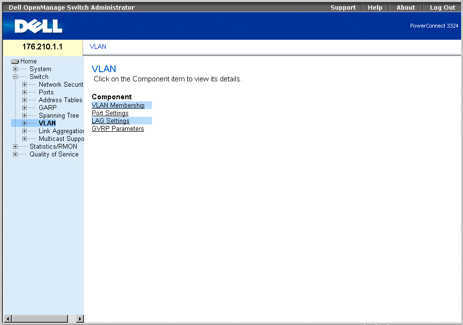
VLAN Page
The VLAN page contains links for defining the following:
Defining VLAN Members
The VLAN Membership page allows network managers to define VLAN groups. To open the VLAN Membership page:
- Click Switch > VLAN > VLAN Membership in the Tree View. The VLAN Membership page opens.
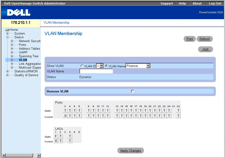
VLAN Membership Page
The VLAN Membership page is divided into the following sections:
VLAN Membership Section
The VLAN Membership Section contains parameters for assigning VLAN membership to ports. PowerConnect 3324/3348 supports up to 256 VLANs.
 |
NOTE: All ports must have a defined PVID. If no other value is configured, use the default
VLAN PVID.
|

VLAN Membership Section
The VLAN Membership Section contains the following fields:
- Show VLAN—Lists and displays specific VLAN information according to:
- VLAN ID—Displays VLANs by VLAN ID. The default ID for the VLAN is 1. If the VLAN has an ID that is the current port Port Default VLAN ID (PVID), and the ID is deleted from the port, the port PVID is set to 1. VLAN number 1 cannot be deleted from the system. The VLAN range is 1-4095. VLAN 4095 is the Discard VLAN.
- VLAN Name—Displays VLAN according to the VLAN name.
- VLAN Name—Displays or defines a user name for the VLAN.
- Status—Indicates the VLAN type. VLANs are user-defined (permanent), created through GVRP, or are default VLANs. The possible field values are:
- Dynamic—Indicates the VLAN was dynamic created through GVRP.
- Static—Indicates the VLAN is user-defined.
- Default—Indicates the VLAN is the default VLAN.
- Remove—Removes the VLAN from the VLAN Membership Table. The possible field values are:
- Checked—Removes the VLAN group from the VLAN Membership Table.
- Unchecked—Maintains the VLAN group in the VLAN Membership Table.
Adding new VLANs:
- Open the VLAN Membership page.
- Click Add. The Create New VLAN page opens:
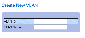
Create New VLAN Page
- Define the VLAN ID and VLAN Name fields.
- Click Apply Changes. The new VLAN is added, and the device is updated.
Modifying VLAN Name Groups:
- Open the VLAN Membership page.
- Select a VLAN in the Show VLAN field.
- Modify the VLAN Name field.
- Click Apply Changes. The VLAN membership information is modified, and the
device is updated.
Deleting a VLAN:
- Open the VLAN Membership page.
- Select a VLAN in the Show VLAN field.
- Check the Remove check box.
- Click Apply Changes. The VLAN is deleted, and the device is updated.
Defining VLAN Membership Groups Using CLI Commands
The following table summarizes the equivalent CLI commands for defining VLAN membership groups as displayed in the VLAN Membership page.
|
CLI Command
|
Description
|
|---|
vlan database | Enters the interface configuration (VLAN) mode. |
vlan {vlan-range} | Creates a VLAN. |
name string | Adds a name to a VLAN. |
The following is an example of the CLI commands:
Console # vlan database
Console (config-switch)#
Console (config-switch)# vlan 1972
Console (config-switch)# exit
Console (config)# interface vlan 19
Console (config-if)# name Marketing
VLAN Port Membership Table
The VLAN Port Membership Table contains a port table for assigning ports to VLANs. Ports are assigned VLAN membership by toggling through the port control settings. Ports can have the following values:
VLAN Port Membership Control Settings
|
Port Control
|
Definition
|
|---|
T | The interface is a member of a VLAN. All packets forwarded by the interface are tagged. The packets contain VLAN information. |
U | The interface is a member of this member. Packets forwarded by the interface are untagged. |
F | The interface is denied membership to a VLAN via GVRP. |
Blank | The interface is not a member of this VLAN. Packets associated with the VLAN are not forwarded. |
 |
NOTE: Ports that are LAG members are not displayed in the VLAN Port Membership Table.
|
The VLAN Port Membership Table displays the ports and the ports states, as well as LAGs.

VLAN Port Membership Table
Assigning ports to a VLAN group:
- Open the VLAN Membership page.
- Select a VLAN from the Show VLAN drop-down list.
- Select ports in the Port Membership Table, and assign the port a value (v, t, f, or b).
- Click Apply Changes. The ports are assigned to the VLAN group, and the device is
updated.
Deleting VLANs:
- Open the VLAN Membership page.
- Select a VLAN from the Show VLAN drop-down list.
- Check the Remove check box.
- Click Apply Changes. The VLAN group is deleted, and the device is updated.
Assigning Ports to VLAN Groups Using CLI Commands
The following table summarizes the equivalent CLI commands for assigning ports to VLAN groups as displayed in the VLAN Membership page.
|
CLI Command
|
Description
|
|---|
vlan database | Enters the interface configuration (VLAN) mode.
|
vlan {vlan-range} | Creates or deletes a VLAN.
|
interface vlan vlan-id | Enters the interface configuration (VLAN) mode to configure an existing VLAN.
|
name string | Adds a name to a VLAN.
|
interface range ethernet {port-range | all} | Enables command execution on multiple ports at the same time.
|
switchport forbidden vlan {add vlan-list | remove vlan-list} | Forbids adding specific VLANs to the port
|
The following is an example of the CLI commands:
Console # vlan database
Console (config-vlan)# vlan 1972
Console (config-vlan)# exit
Console (config)# interface vlan 1972
Console (config-if)# name Marketing
Console (config-if)# exit
Console (config)# interface range ethernet 1/e18 - e20
Defining VLAN Ports Settings
The VLAN Port Settings page provides parameters for managing ports that are part of a VLAN.
The Port Default VLAN ID (PVID) is configured on the VLAN Port Settings page. All untagged packets arriving to the device are tagged by the ports PVID. To open the VLAN Port Settings page:
- Click Switch > VLAN > Port Settings in the Tree View. The VLAN Port Settings page opens.
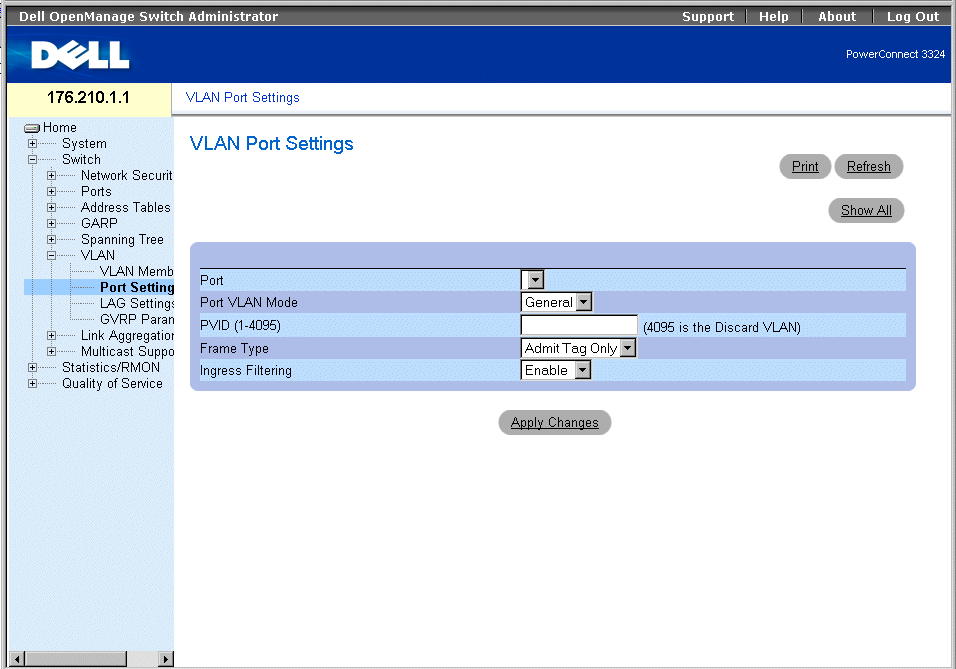
VLAN Port Settings Page
The VLAN Port Settings page contains the following fields:
- Port—Indicates the port number included in the VLAN.
- Port VLAN Mode—Designates the port VLAN mode.The possible field values are:
- General—Indicates that the port belongs to one or more VLANs, and each VLAN is user-defined as tagged or untagged (full 802.1Q mode). Ingress filtering can be disabled only in general-mode ports.
- Access—Indicates that the port belongs to a single untagged VLAN. Defining the port VLAN mode as access implies that the ports accept all untagged frames, and all frames tagged with the VID currently set as the port's PVID. Access mode ports are intended to connect end-stations to the system, especially when the end-stations are incapable of generating VLAN tags. Ingress filtering is enabled.
- Trunk—Indicates that the port belongs to a VLAN in which all frames are tagged. Ingress filtering is enabled on trunk-mode ports.
- PVID (1-4095)—Assigns a VLAN ID to untagged packets. This is only implemented for general mode ports. The possible field value range is 1-4095.
 |
NOTE: VLAN 4095 is the discard VLAN.
|
- Frame Type—Indicates the packet type accepted on the port. The possible field values are:
- Admit Tag Only—Indicates that only tagged packets are accepted on the port.
- Admit All—Indicates that both tagged and untagged packets are accepted on the port.
- Ingress Filtering—Enables Ingress filtering on the port. Ingress filtering discards packets that are associated with a VLAN that does not include the ingress port. The possible field values are:
- Enable—Enables ingress filtering on the port.
- Disable—Disable ingress filtering on the port.
Assigning port settings:
 |
NOTE: Ingress filtering can only be disabled on ports set to general VLAN mode.
|
- Open the VLAN Port Settings page.
- Define the Port Mode, PVID, Frame Type, and the Ingress Filtering fields.
- Click Apply Changes. The VLAN port parameters are defined, and the device is
updated.
Displaying the VLAN Port Table:
- Open the VLAN Port Settings page.
- Click Show All. The VLAN Port Table opens.
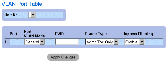
VLAN Port Table
In addition to the VLAN Port Settings page fields, the VLAN Port Table page also displays the following field:
- Unit—Indicates the stacking unit number for which the VLAN port information is displayed.
Assigning Ports to VLAN Groups Using CLI Commands
The following table summarizes the equivalent CLI commands for assigning ports to VLAN groups as displayed in the VLAN Port Settings page.
|
CLI Command
|
Description
|
|---|
interface ethernet interface | Enters the interface configuration mode to configure an ethernet type interface.
|
switchport mode {access | trunk | general} | Configures a port VLAN membership mode.
|
switchport general pvid vlan-id | Configure the Port VLAN ID (PVID) when the interface is in general mode.
|
switchport general allowed vlan add vlan-list [tagged | untagged] | Adds VLANs to a general port.
|
switchport general allowed vlan remove vlan-list | Removes VLANs from a general port.
|
switchport general ingress-filtering disable | Disables port ingress filtering.
|
The following is an example of the CLI commands:
Console (config)# interface range ethernet 1/e18 - e20
Console (config-if)# switchport mode access
Console (config-if)# switchport general pvid 234
Console (config-if)# switchport general allowed vlan add 1,2,5,6
tagged
Console (config-if)# switchport general ingress-filtering disable
Defining VLAN LAG Settings
The VLAN LAG Settings page provides parameters for managing LAGs that are part of a VLAN. VLANs are composed of individual ports or LAGs. Untagged packets entering the switch on a LAG are tagged as specified by the LAG's PVID. To open the VLAN LAG Settings page:
- Click Switch > VLAN > LAG Settings in the Tree View. The VLAN LAG Settings page opens.
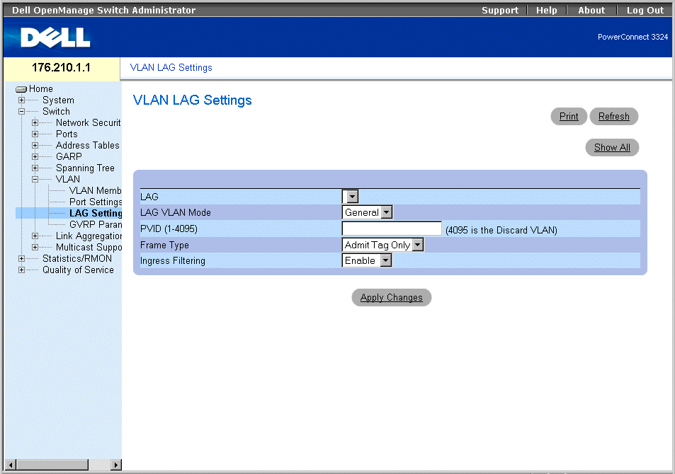
VLAN LAG Setting Page
The VLAN LACP Parameters page contains the following fields:
- LAG—Indicates the LAG number included in the VLAN.
- Port Mode—Indicates the port mode. The possible field values are:
- General—Indicates that the LAG belongs to one or more VLANs, and each VLAN is user-defined as tagged or untagged (full 802.1Q compliance).
- Access—Indicates that the LAG belongs to a single untagged VLAN.
- Trunk—Indicates that the LAG belongs to a VLAN where all frames are tagged (except for an optional single native VLAN).
- PVID—Assigns a VLAN ID to untagged packets. In order for LAGs to assign PVIDs, the LAG must be defined as untagged in the VLAN Port Membership Table.
- Frame Type—Indicates the packet type accepted by the LAG. The possible field values are:
- Admit Tag Only—Indicates that only tagged packets are accepted by the LAG.
- Admit All—Indicates that both tagged and untagged packets are accepted by the LAG.
- Ingress Filtering—Enables ingress filtering by the LAG. Ingress filtering discards packets which do not include an ingress port. The possible field values are:
- Enable—Enables ingress filtering by the LAG.
- Disable—Disable ingress filtering by the LAG.
Assigning LAG settings:
- Open the VLAN LAG Settings page.
- Define the Port Mode, PVID, Frame Type, and the Ingress Filtering fields.
- Click Apply Changes. The VLAN LAG parameters are defined, and the device is
updated.
Displaying the VLAN LAG Table:
- Open the VLAN LAG Settings page.
- Click Show All. The VLAN LAG Table opens.

VLAN LAG Table
Assigning LAGs to VLAN Groups Using CLI Commands
The following table summarizes the equivalent CLI commands for assigning LAGs to VLAN groups as displayed in the VLAN LAG Settings page.
|
CLI Command
|
Description
|
|---|
switchport mode {access | LAG | general} | Configures a port VLAN membership mode. |
switchport LAG native vlan vlan-id | Defines the LAG as a member of the specified VLAN, and the VLAN ID as the "port default VLAN ID (PVID)". |
switchport general pvid vlan-id | Configure the Port VLAN ID (PVID) when the interface is in general mode. |
switchport general allowed vlan add vlan-list [tagged | untagged] | Adds VLANs to a general port. |
switchport general allowed vlan remove vlan-list [tagged | untagged] | Removes VLANs from a general port. |
switchport general acceptable-frame-types tagged-only | Discards untagged frames at ingress. |
switchport general ingress-filtering off | Disables port ingress filtering. |
The following is an example of the CLI commands:
Console (config)# interface port channel 1 1/e8
Console (config-if)# switchport mode access
console (config-if)# switchport LAG native vlan 123
Console (config-if)# switchport general pvid 234
Console (config-if)# switchport general allowed vlan add 1,2,5,6
tagged
Console (config-if)# switchport general acceptable-frame-types
tagged-only
Console (config-if)# switchport general ingress-filtering disable
Configuring GVRP
The GARP VLAN Registration Protocol (GVRP) protocol is specifically provided for automatic distribution of VLAN membership information among VLAN-aware bridges. GVRP allows VLAN-aware bridges to automatically learn VLANs to bridge ports mapping, without having to individually configure each bridge, and to register VLAN membership.
To minimize the memory requirements when running the GVRP protocol, two proprietary tuning variables have been added to the standard variables:
- Maximum number of GVRP VLANs—Displays the number of GVRP VLANs allowed to participate in GVRP operation.
- Maximum number of GVRP VLANs after Reset—Sets another value for GVRP VLANs and is used for tuning. This value becomes valid after reset only.
The maximum number of GVRP VLANs includes all the VLANs participating in GVRP operation regardless whether they are static or dynamic.
The following should be considered when specifying the maximum number of VLANs participating in GVRP by setting the maximum number of GVRP VLANs after reset value:
- The default maximum number of GVRP VLANs is equal to 128 because of the memory restrictions.
- The maximum number of VLANs (managed through Max VLANs MIB variable) limits the maximum number of GVRP VLANs.
To ensure the correct operation of the GVRP protocol, users are advised to set the maximum number of GVRP VLANs equal to a value which significantly exceeds the sum of:
- The number of all static VLANs both currently configured and expected to be configured.
- The number of all dynamic VLANs participating in GVRP both currently configured (initial number of dynamic GVRP VLANs is 128) and expected to be configured.
Increasing the value of maximum number of the GVRP VLANs to a value beyond the sums, allows users to run GVRP, and not reset the device to receive a larger amount of GVRP VLANs. For example, if three VLANs exist and another two VLANs are expected to be configured as a result of VLAN static or dynamic registration, set the maximum number of GVRP VLANs after reset to 10. To open the GVRP Parameters page:
- Click Switch > VLAN > GVRP Parameters in the Tree View. The GVRP Parameters page opens.

GVRP Parameters Page
The GVRP Parameters page contains the following fields:
- GVRP Global Status—Enables GVRP on the device. The possible field values are:
- Enabled—Indicates GVRP is enabled on the device.
- Disabled—Indicates GVRP is disabled on the device. This field value is the default.
- Interface—Indicates the specific interface for which GVRP is enabled. The possible field values are:
- Port—Indicates the specific port for which GVRP is enabled.
- LAG—Indicates the specific LAG for which GVRP is enabled.
- GVRP State—Indicates if GVRP is enabled on a port. The possible field values are:
- Enable—Enables GVRP on the interface.
- Disable—Disables GVRP on the interface. This is the default value.
- Dynamic VLAN Creation—Enables VLAN creation through GVRP. The possible field values are:
- Enable—Enables creating VLANs through GVRP.
- Disable—Disables creating VLANs through GVRP.
- GVRP Registration—Enables GVRP registration status. The possible field values are:
- Enable—Enables VLAN registration through GVRP.
- Disable—Disables VLAN registration through GVRP.
Enabling GVRP on the device:
- Open the GVRP Parameters page.
- Select Enable in the GVRP Global Status field.
- Click Apply Changes. GVRP is enabled on the device.
Defining GVRP Ports:
- Open the GVRP Parameters page.
- Click Show All. The GVRP Parameters page opens. The GVRP Port Parameters
contains parameters for enabling GVRP on a port and permitting port to participate in
VLAN registration through GVRP. In addition, the GVRP Port Parameters Table also
contains information about the VLAN registration mode. Specific ports can also be
blocked from registering or being used in a VLAN.
- Select a port.
- Define the GVRP State, Dynamic VLAN Creation, VLAN Registration, and the
GVRP Registration fields.
- Click Apply Changes. GVRP is enabled on the port, parameters are defined, and the
device is updated.
Displaying the GVRP Port Parameters Table:
- Open the GVRP Parameters page.
- Click Show All. The GVRP Port Parameters Table opens.
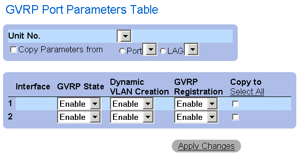
GVRP Port Parameters Table
In addition to the field displayed in the GVRP Parameters page , the GVRP Port Parameters Table page also displays the following fields:
- Unit—Indicates the stacking unit number for which the GVRP information is displayed.
- Copy Parameters From—Indicates the specific interface from which the GVRP parameters are copied.
- Copy To—Indicates the ports to which the GVRP parameters are copied.
Configuring GVRP Using CLI Commands
The following table summarizes the equivalent CLI commands for configuring GVRP as displayed in the GVRP Parameters page.
|
CLI Command
|
Description
|
|---|
gvrp enable | Enables GVRP globally. |
gvrp enable | Enables GVRP on an interface. |
gvrp vlan-creation-forbid | Enables or disables dynamic VLAN creation. |
gvrp registration-forbid | Unregisters all VLANs, and prevents dynamic VLAN creation or registration on the port. |
show gvrp configuration [ethernet interface | port-channel port-channel-number] | Displays GVRP configuration information, including timer values, whether GVRP and dynamic VLAN creation is enabled, and which ports are running GVRP. |
gvrp max-vlan number | Configures the maximum number of VLANs when GVRP is enabled. |
The following is an example of the CLI commands:
Console (config)# gvrp enable
Console (config)# interface ethernet 1/e8
Console (config-if)# gvrp enable
Console (config-if)# gvrp-vlan-creation-forbid
Console (config-if)# gvrp registration-forbid
Console# show gvrp configuration
GVRP Feature is currently enabled on the switch.
Maximum VLANs: 256, Maximum VLANs after reset: 256.
Port(s)Status Registration Dynamic VLAN Timers (milliseconds)
Creation Join Leave Leave All
------ ------- ---------- -------- ----- ----- -----
2/1 Enabled Normal Enabled 200 600 10000
4/4 Enabled Normal Enabled 200 600 10000
Aggregating Ports
Port Aggregation optimizes port usage by linking a group of ports together to form a single Link Aggregated Group (LAG). Port Aggregation multiplies the bandwidth between the devices, increases port flexibility, and provides link redundancy. Both the PowerConnect 3324 and PowerConnect 3348 support up to six LAGs, and eight ports per LAG per stack or stand-alone unit.
Each LAG is composed of ports of the same speed, set to full-duplex operations. Ports in a LAG, can be of different media types (UTP/Fiber, or different fiber types), provided they operate at the same speed.
Aggregated links can be assigned manually or automatically by enabling the Link Aggregation Control Protocol (LACP) on the relevant links. PowerConnect 3324/3348 provides LAG Load Balancing based on both source MAC addresses and destination MAC addresses.
Aggregated links are treated as a single logical port by the system. Specifically, the Aggregated link has similar port attributes to a non-aggregated port, including auto-negotiation, speed, duplex setting, and so forth.
PowerConnect 3324/3348 supports both static LAGs and Link Aggregation Control Protocol (LACP) LAGs. LACP LAGs negotiate aggregated port links with other LACP ports located on a different device. If the other device ports are also LACP ports, the devices establish a LAG between them.
Use the following guidelines when adding ports to a LAG for either a standalone or a stacking configuration:
- No Layer 3 interface is defined on the port.
- The port does not belong to any VLAN.
- The port does not belong to any other LAG.
- The port is not a mirrored port.
- The port's 802.1p priority is equal to the LAG's 802.1p priority.
- No ACL is defined on the port.
- QoS Trust in not disabled on the port.
- GVRP is not enabled.
 |
NOTE: Ports can be configured as LACP ports only if the ports are not part of a previously
configured LAG.
|
PowerConnect 3324/3348 uses a hash function to determine which frames are carried on which aggregated-link member. The hash function statistically load-balances the aggregated link members. PowerConnect 3324/3348 considers an aggregated link to be a single logical port.
Each aggregated link has an aggregated link port type, including Gigabit Ethernet ports and Fast Ethernet ports. Ports can be added to an aggregated link only if they are the same port type. When ports are removed from an aggregated link, the ports revert to the original port settings. To open the Link Aggregation page:
- Click Switch > Link Aggregation in the Tree View. The Link Aggregation page opens.
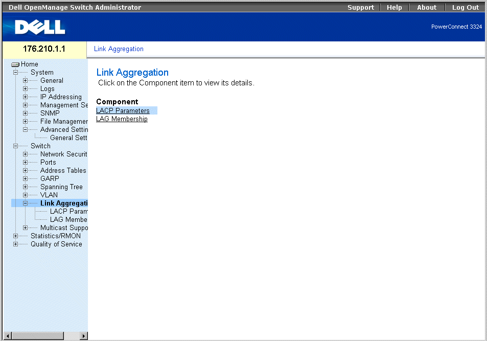
Link Aggregation Page
This section includes the following topics:
Defining LACP Parameters
The LACP Parameters page contains information for configuring LACP LAGs. Aggregate ports can be linked into link-aggregation port-groups. Each group is comprised of ports with the same speed.
Aggregated links can be manually set up or automatically established by enabling the Link Aggregation Control Protocol (LACP) on the relevant links. To open the LACP Parameters page:
- Click Switch > Link Aggregation > LACP Parameters in the Tree View. The LACP Parameters page opens.

LACP Parameters Page
The LACP Parameters page contains the following sections:
Global Parameters
Global Parameters contains information for assigning LACP priority. Aggregate ports can be linked into link-aggregation port-groups. LAGs may be set up manually, by explicit user assignment, or automatically by enabling the Link Aggregation Control Protocol (LACP) on the relevant LAGs.
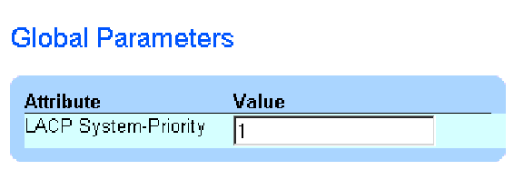
Global Parameters
The Global Parameters section contains the following field:
- LACP System Priority—Indicates the LACP priority value. The possible range is 1-65535. The default value is 1.
Defining Global Parameters:
- Open the LACP Parameters page.
- Scroll to the Global Parameters section.
- Define the LACP System Priority and the LACP Timeout fields.
- Click Apply Changes. The Global Parameters are defined, and the device is updated.
Port Parameters Table
The Port Parameters Table contains information for assigning LACP priority and timeout values to ports:

Port Parameters Table
The Port Parameters table contains the following fields:
- Select Port—Indicates the port number.
- LACP Port Priority—Indicates the port LACP priority value. The default is 1.
- LACP Timeout—Assigns an administrative LACP timeout.The possible field values are:
- Short—Specifies a short timeout value.
- Long—Specifies a long timeout value.
Defining Port Parameters:
- Open the LACP Parameters page.
- Scroll to the Link Aggregation Port Parameters Table.
- Define the LACP System Priority and the LACP Timeout fields.
- Click Apply Changes. The Link Aggregation Global Parameters are defined, and the
device is updated.
Displaying the LACP Parameters Table:
- Open the LACP Parameters page.
- Click Show All. The LACP Parameters Table opens.
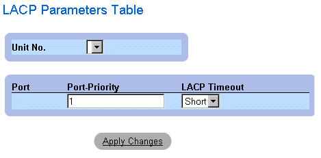
LACP Parameters Table
In addition to the LACP Parameters page fields, the LACP Parameters Table page also displays the following field:
- Unit—Indicates the stacking unit number for which the LACP information is displayed.
Configuring LACP Parameters Using CLI Commands
The following table summarizes the equivalent CLI commands for configuring LACP parameters as displayed in the Link Aggregation page.
|
CLI Command
|
Description
|
|---|
lacp system-priority value | Configures the system priority. |
lacp port-priority value | Configures the priority value for physical ports. |
lacp timeout {long | short} | Assigns an administrative LACP timeout. |
show lacp ethernet interface [parameters | statistics | protocol-state] | Displays LACP information for ethernet ports. |
show lacp port-channel [port_channel_number] | Displays LACP information for a Port-channel. |
The following is an example of the CLI commands:
Console (config)# lacp system-priority 120
Console (config)# interface ethernet 1/e8
Console (config-if)# lacp port-priority 247
Console (config-if)# lacp timeout long
Console (config-if)# exit
Console# show lacp ethernet 1/e1 statistics
Port 1/e1 LACP Statistics:
LACP PDUs sent:2
LACP PDUs received:2
Defining LAG Membership
The LAG Membership page allows network managers to assign ports to LAGs. LAGs can include up to 8 ports. Currently PowerConnect 3324/3348 supports 6 LAGs per system, whether the device is a standalone device or in a stack. The LAG Membership Table contains the following rows:
- LACP—Indicates if the port is dynamic by allowing it to become a LAG member.
- LAG—Adds a port to a LAG, and indicates the specific LAG to which the port belongs.
To open the LAG Membership page:
- Click Switch > Link Aggregation > LAG Membership Tab in the Tree View. The LAG Membership page opens.
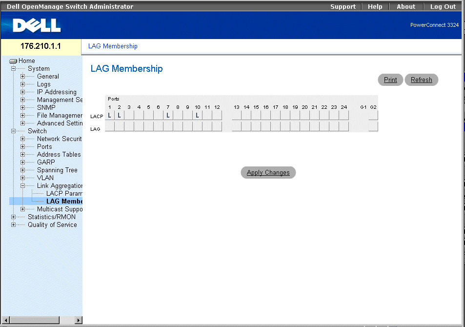
LAG Membership Page
Adding a port to a LAG:
- Open the LAG Membership page.
- Toggle under the port number to assign the LAG setting and number.
- Click Apply Changes. The port is added to the LAG, and the device is updated.
Assigning Ports to LAGs Using CLI Commands
The following table summarizes the equivalent CLI commands for assigning ports to LAGs as displayed in the LAG Membership page.
|
CLI Command
|
Description
|
|---|
channel-group port-channel-number mode {on | auto} | Configures a port to a Port channel. |
show interface port_channel | Displays the interfaces attached to a LAG. |
The following is an example of the CLI commands:
Console# channel-group port-channel-number mode on auto 1
Port-Channel 1:Port Type 1000 Ethernet
Actor
System Priority:1
MAC Address: 000285:0E1C00
Admin Key: 29
Oper Key: 29
Partner
System Priority:0
MAC Address: 000000:000000
Oper Key: 14
Multicast Forwarding Support
Multicast forwarding allows a single packet to be forwarded to multiple destinations. L2 Multicast service is based on a L2 switch receiving a single packet addressed to a specific multicast addresses. Multicast forwarding creates copies of the packet, and transmits the packets to the relevant ports.
PowerConnect 3324/3348 supports both:
- Forwarding L2 Multicast Packets—Enabled by default.
- Filtering L2 Multicast Packets—Enables forwarding L2 packets to ports VLAN. If multicast filtering is disabled, multicast packets are flooded to all relevant VLAN ports.
To open the Multicast Support page:
- Click Switch > Multicast Support in the Tree View. The Multicast Support page opens.
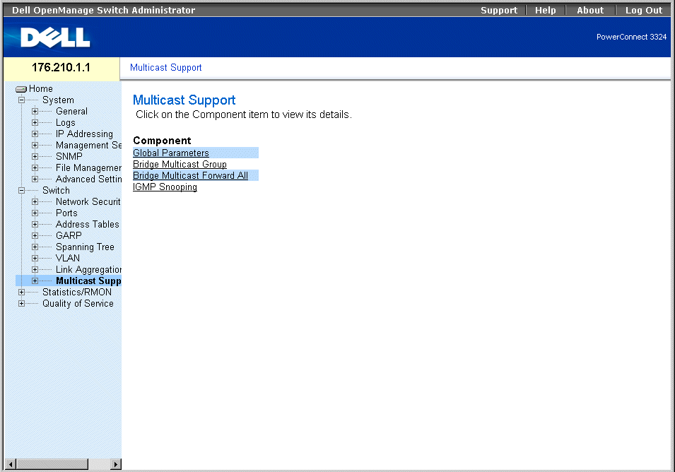
Multicast Support Page
The Multicast Support page includes links to the following topics:
Defining IGMP Snooping Settings
Layer 2 switching forwards multicast packets to all relevant VLAN ports by default, treating the packet as a multicast packet. This type of traffic forwarding is functional; however, irrelevant ports also receive multicast traffic, causing increased network traffic.
IGMP snooping eliminates unnecessary multicast traffic by examining IGMP frames while they are forwarded from stations to a multicast routers.
When IGMP snooping is globally enabled, the switching ASIC is programmed to forward all IGMP frames to the CPU. The CPU analyzes the incoming frames and determines which ports want to join which Multicast groups, which ports have Multicast routers generating IGMP queries, and what Routing protocols are forwarding packets and Multicast traffic. A port wishing to join a specific multicast group issues an IGMP report specifying that multicast group.
The Multicast Global Parameters page allows network managers to enable IGMP Snooping and Multicast Filtering in general on the device. To open the Multicast Global Parameters page:
- Click Switch > Multicast Support > Global Parameters in the Tree View. The Multicast Global Parameters page opens.
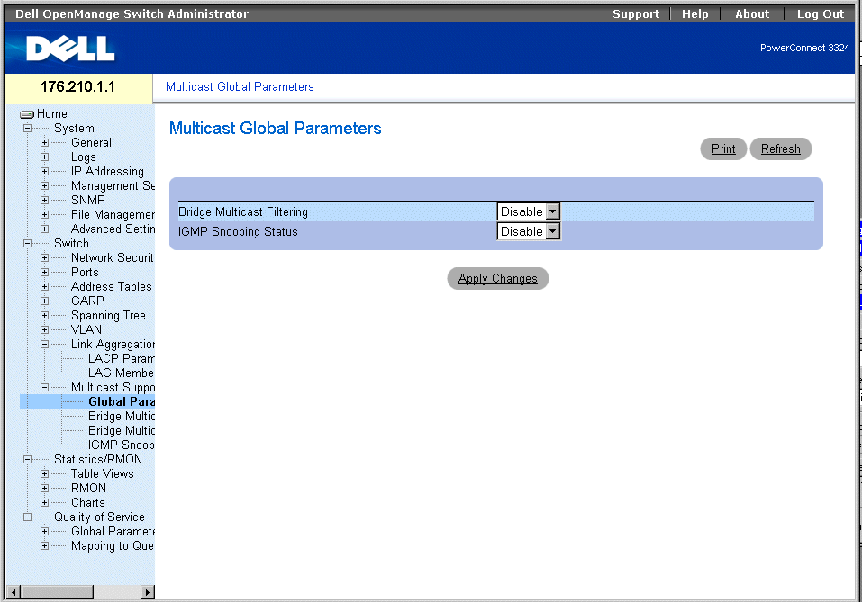
Multicast Global Parameters Page
The Multicast Global Parameters page contains the following fields:
- Bridge Multicast Filtering—Indicates if bridge multicast filtering is enabled on the device. The possible field values are:
- Enabled—Enables bridge multicast filtering on the device.
- Disabled—Disables bridge multicast filtering on the device. This is the default value.
- IGMP Snooping Status—Indicates if IGMP snooping is enabled on the device. The possible field values are:
- Enabled—Enables IGMP snooping on the specific VLAN.
- Disabled—Disables IGMP snooping on the specific VLAN. This is the default value.
Enabling bridge multicast filtering on the device:
- Open the Multicast Global Parameters page.
- Select Enable in the bridge multicast filtering field.
- Click Apply Changes. Bridge Multicast is enabled on the device.
Enabling IGMP snooping on the device:
- Open the Multicast Global Parameters page.
- Select Enable in the IGMP Snooping Status field.
- Click Apply Changes. IGMP snooping is enabled on the device.
Enabling Multicast Forwarding and IGMP Snooping Using CLI Commands
The following table summarizes the equivalent CLI commands for enabling multicast forwarding and IGM snooping as displayed in the Multicast Support page.
|
CLI Command
|
Description
|
|---|
bridge multicast filtering | Enables filtering of multicast addresses. |
ip igmp snooping | Enables Internet Group Management Protocol (IGMP) snooping. |
The following is an example of the CLI commands:
Console (config)# bridge multicast filtering
Console (config)# ip igmp snooping
Adding Bridge Multicast Group Members
The Bridge Multicast Group page displays the ports and LAGs attached to the multicast service group in the Port and LAG Table. The Port and LAG tables also reflect the manner in which the port or LAGs joined the multicast group. Ports can be added either to existing groups or to new multicast service groups. The Bridge Multicast Group page permits new multicast service groups to be created. The Bridge Multicast Group page also assigns ports to a specific multicast service address group. To open the Bridge Multicast Group page:
- Click Switch > Multicast Support > Bridge Multicast Group in the Tree View. The Bridge Multicast Group page opens.
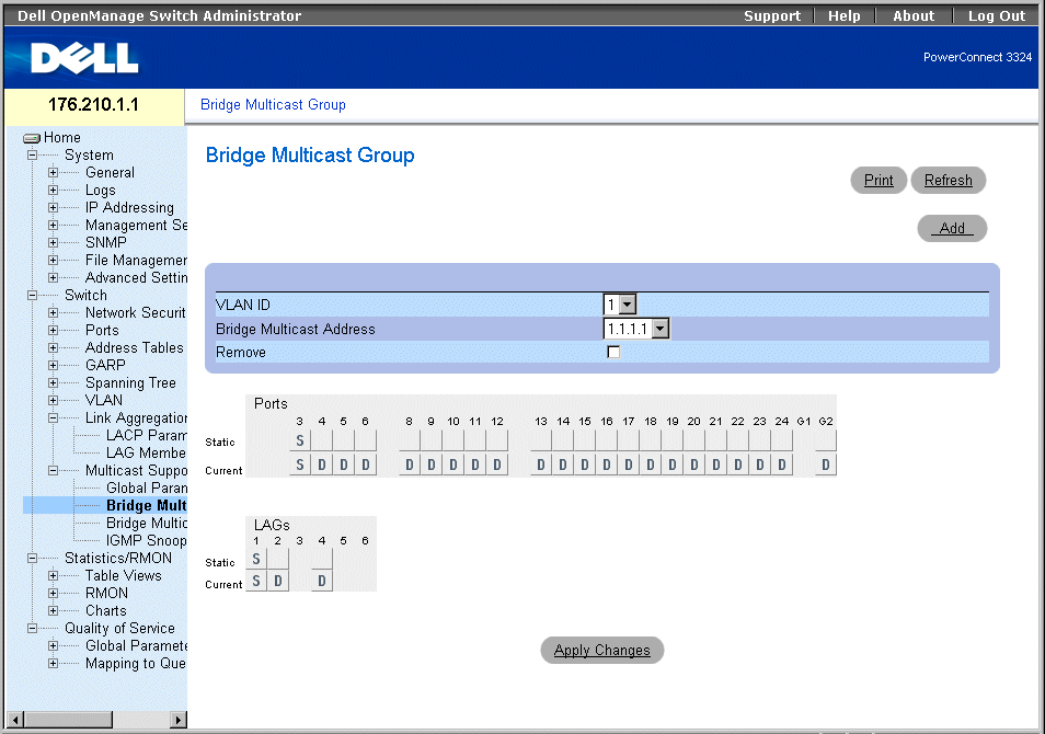
Bridge Multicast Group Page
The Bridge Multicast Group page contains the following fields:
- VLAN ID—Identifies a VLAN.
- Bridge Multicast Address—Identifies the multicast group IP address.
- Remove—Removes a bridge multicast group specified by its address.
- Checked—Removes the bridge multicast address.
- Unchecked—Maintains the bridge multicast address.
- Ports Table—Lists the port that can be added to a multicast service.
- LAGs Table—Lists the LAGs that can be added to a multicast service.
The IGMP Port/LAG Members Table figure displays IGMP Port/LAG member status.

IGMP Port/LAG Members Table
The IGMP Port/LAG Members Table Control Settings Table contains the settings for managing IGMP port and LAG members.
|
Port Control
|
Definition
|
|---|
D | Indicates that the port/LAG has joined the multicast group dynamically in the Current row. |
S | Attaches the port to the multicast group as static member in the Static Row. Indicates that the port/LAG has joined the Multicast group statically in the Current row. |
F | Indicates that the port is forbidden to join this multicast group. |
Blank | Indicates that the port is not attached to the multicast group. |
IGMP Port/LAG Members Table Control Settings
Defining ports to receive multicast service:
- Open the Bridge Multicast page.
- Define the VLAN ID and the Bridge Multicast Address fields.
- Toggle a port to S to join the port to a selected multicast group, or Toggle a port to F
to forbid the port from joining that multicast group.
- Click Apply Changes. The port is assigned to the multicast group, and the device is
updated.
Assigning LAGs to receive multicast service:
- Open the Bridge Multicast page.
- Define the VLAN ID and the Bridge Multicast Address fields.
- Toggle the LAG to S to join the LAG to the selected multicast group, or toggle a port
to F to forbid the port from joining a multicast group.
- Click Apply Changes. The LAG is assigned to the multicast group, and the device is
updated.
Managing Multicast Service Members Using CLI Commands
The following table summarizes the equivalent CLI commands for managing multicast service members as displayed in the Bridge Multicast Group page.
|
CLI Command
|
Description
|
|---|
bridge multicast address {mac-multicast-address | ip-multicast-address} {add | remove} {ethernet interface-list | port-channel port-channel-number-list} | Registers MAC-layer multicast addresses to the bridge table, and adds static ports to the group. |
show bridge multicast address-table [vlan vlan-id] [address mac-multicast-address | ip-multicast-address] [format ip | mac] | Displays multicast MAC address table information. |
The following is an example of the CLI commands:
Console (config)# interface vlan 8
bridge multicast address 0100.5e02.0203
bridge multicast address 0100.5e02.0203 add ethernet 1/e1, 2/e2
Console (config-if)# Exit
Console # show bridge multicast address-table
Vlan MAC Address type Ports
---- -------------- ----- -------------------
1 0100.5e02.0203 static 1/e1, 2/e2
19 0100.5e02.0208 static 1/e1-8
19 0100.5e02.0208 dynamic 1/e9-11
Forbidden ports for multicast addresses:
Vlan MAC Address Ports
---- -------------- -------------------
1 0100.5e02.0203 2/e8
19 0100.5e02.0208 2/e8
Assigning Multicast Forward All Parameters
The Bridge Multicast Forward All page allows network managers to enable attaching ports or LAGs to a switch attached to a neighboring multicast router/switch. Once IGMP snooping is enabled, multicast packets are forwarded to the appropriate port or VLAN.
- Click Switch > Multicast Support > Bridge Multicast > Bridge Multicast Forward All Tab in the Tree View. The Bridge Multicast Forward All page opens.
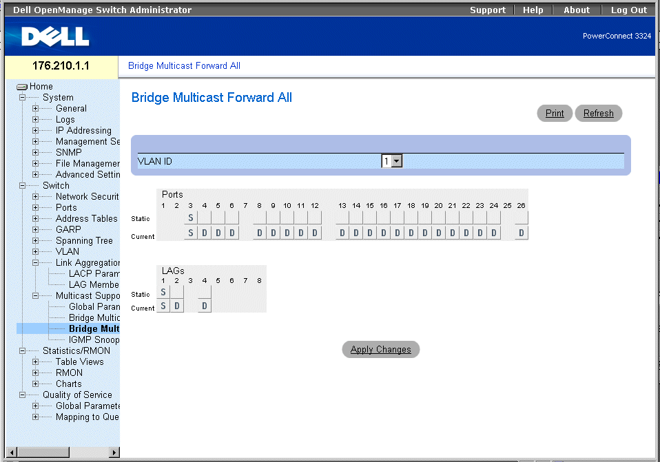
Bridge Multicast Forward All Page
The Bridge Multicast Forward All page contains the following fields:
- VLAN ID—Identifies a frame VLAN and contains information about the multicast group address.
- Ports Table—Lists the port that can be added to a multicast service.
- LAGs Table—Lists the LAGs that can be added to a multicast service.
The Bridge Multicast Forward All page contains the settings for managing switch and port settings.
|
Port Control
|
Definition
|
|---|
D | Attaches the port to the multicast router or switch as a dynamic port. |
S | Attaches the port to the multicast router or switch as a static port. |
F | Indicates that the port if forbidden from joining a multicast group. |
Blank | Indicates that the port is not attached to a multicast router or switch. |
Bridge Multicast Forward All Router/Port Control Settings
Attaching a port to multicast router or switch:
- Open Bridge Multicast Forward All page.
- Define the VLAN ID field.
- Select a port in the Multicast Router Port Table, and assign the port a value.
- Click Apply Changes. The port attached to the multicast router or group is updated.
Attaching a LAG to multicast router or switch:
- Open Bridge Multicast Forward All page.
- Define the VLAN ID field.
- Select a LAG in the Multicast Router Port Table and assign a value to the LAG.
- Click Apply Changes. The LAG attached to the multicast router or group is updated.
Managing LAGs and Ports Attached to Multicast Routers Using CLI Commands
The following table summarizes the equivalent CLI commands for managing LAGs and ports attached to multicast routers as displayed in the Bridge Multicast Forward All page.
|
CLI Command
|
Description
|
|---|
show bridge multicast filtering vlan-id | Displays the multicast configuration. |
bridge multicast forbidden forward-all | Disables forwarding multicast packets on a port. |
bridge multicast forward-all {add | remove} {ethernet interface-list | port-channel port-channel-number-list} | Enables forwarding of all multicast packets on a port. |
The following is an example of the CLI commands:
Console # show bridge multicast filtering
Filtering: Enabled
VLAN: 1
Port Forward-All
Static Status
------ --------- ------
1/e1 Forbidden Filter
1/e2 Forward Forward(s)
1/e3 - Forward(s)
Enabling IGMP Snooping
The IGMP Snooping page allows network managers to add IGMP members. To open the IGMP Snooping page:
- Click Switch > Multicast Support > IGMP Snooping in the Tree View. The IGMP Snooping page opens.
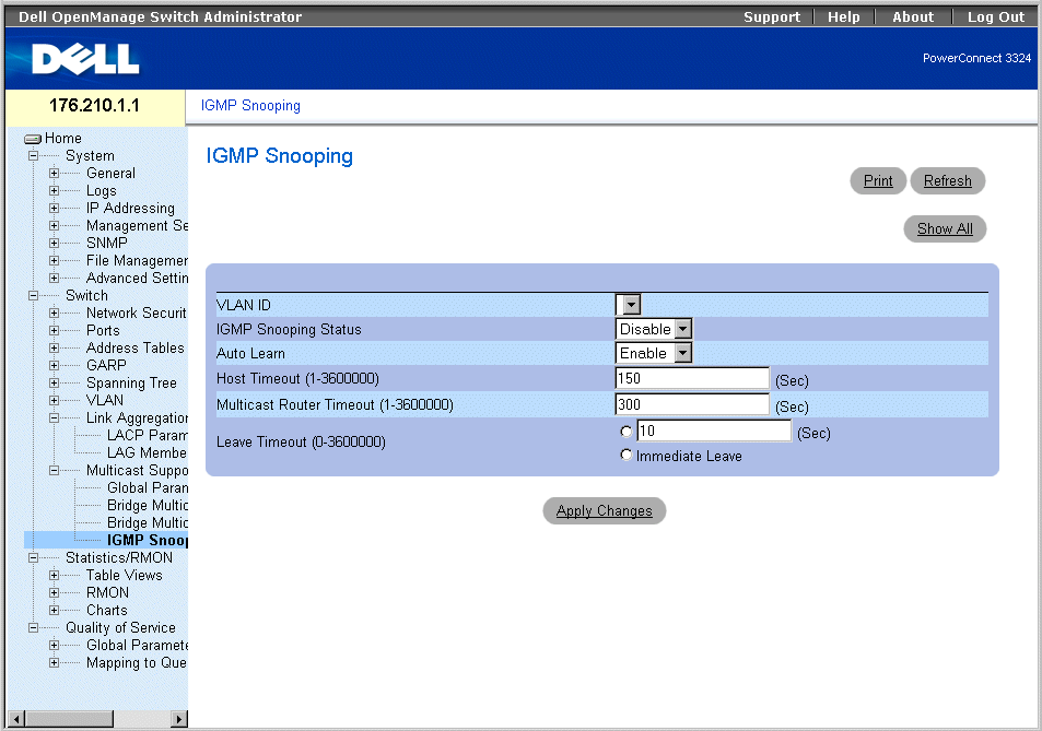
IGMP Snooping Page
The IGMP Snooping page contains the following information:
- VLAN ID—Specifies the VLAN ID.
- IGMP Snooping Status—Enables IGMP snooping on the device. The possible field values are:
- Enable—Enables IGMP snooping on the device.
- Disable—Disables IGMP snooping on the device.
- Auto Learn—Enables automatically learning new multicast group members. The possible field values are:
- Enable—Enables automatically learning new multicast group members.
- Disable—Disables automatically learning new multicast group members.
- Host Timeout (1-3600000)—Indicates the amount of time before an IGMP snooping entry is aged out. The default time is 150 seconds.
- Multicast Router Timeout (1-3600000)—Indicates the amount of time before aging out an Multicast Router entry. The default value is 300 seconds.
- Leave Time Out (1-3600000)—Specifies the amount of time in seconds after a port leave message is received before the entry is aged out. The possible field values are:
- User-Defined—Indicates the user-defined Leave Timeout period.
- Immediate Leave—Specifies an immediate Leave Timeout period.
Displaying the IGMP Snooping Table:
- Open the IGMP Snooping page.
- Click Show All. The IGMP Snooping Table opens.

IGMP Snooping Table
Configuring IGMP Snooping with CLI Commands
The following table summarizes the equivalent CLI commands for configuring IGMP Snooping as displayed in the IGMP Snooping page.
|
CLI Command
|
Description
|
|---|
ip igmp snooping | Enables Internet Group Management Protocol (IGMP) snooping a specific VLAN. |
ip igmp snooping mrouter learn-pim-dvmrp | Enables automatic learning of Multicast router ports in the context of a specific VLAN. |
ip igmp snooping host-time-out time-out | Configures the host-time-out. |
ip igmp snooping mrouter-time-out time-out | Configures the mrouter-time-out. |
ip igmp snooping leave-time-out {time-out | immediate-leave} | Configures the leave-time-out. |
show ip igmp snooping mrouter [interface vlan-id] | Displays information on dynamically learned multicast router interfaces. |
The following is an example of the CLI commands:
Console (config)# interface vlan 2
Console (config-if)# ip igmp snooping
Console (config-if)# ip igmp snooping mrouter learn-pim-dvmrp
Console (config-if)# ip igmp snooping host-time-out 300
Console (config-if)# ip igmp snooping mrouter-time-out 300
Console (config-if)# exit
Console (config)# interface vlan 2
Console (config-if)# ip igmp snooping leave-time-out 60
Console (config-if)# exit
Console (config)# exit
Console # show igmp snooping mrouter interface 1000
VLAN Ports
------- -----------------------------------------
200 1/e1, 2/e1
Back to Contents Page
 Configuring Network Security
 Configuring the Spanning Tree Protocol


