Back to Contents Page
Configuring System Information
Dell™ PowerConnect™ 3324/3348
User's Guide
 Defining General Device Information
 Managing Logs
 Defining Device IP Addresses
 Managing Device Security
 Defining SNMP Parameters
 Managing Files
 Defining Advanced Settings
This section provides information about defining system parameters including security features, downloading device software, and resetting the device. To open the System page:
- Click System in the Tree View. The System page opens.
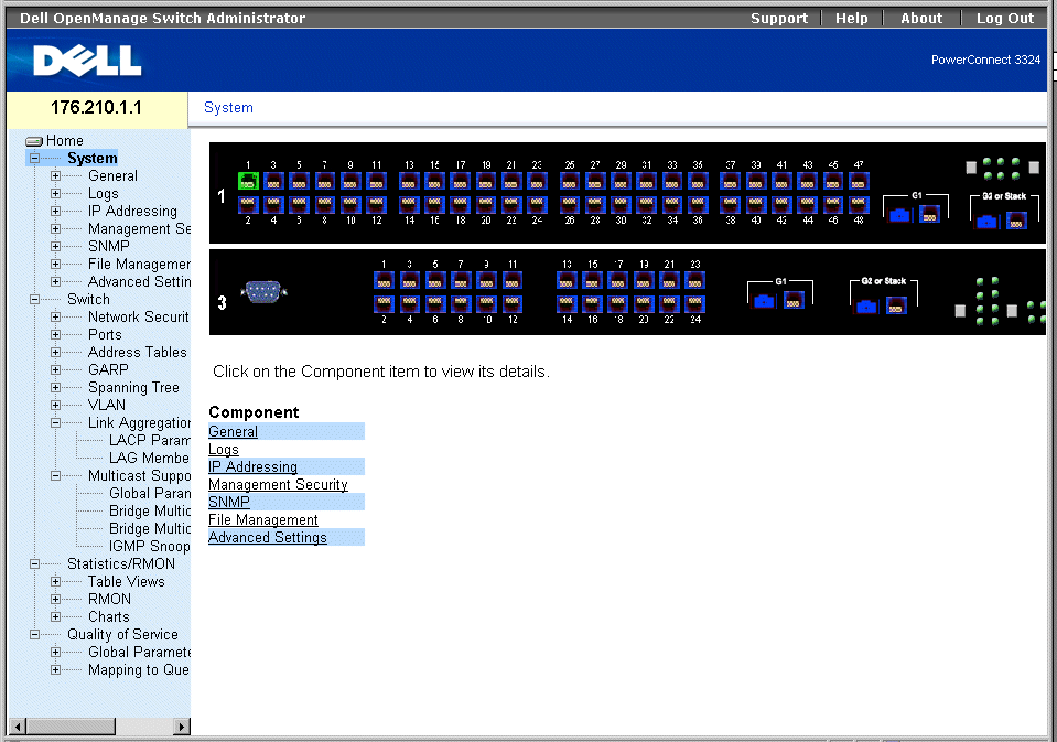
System Page
Defining General Device Information
The General page contains links to pages that allow network managers to configure device parameters, including:
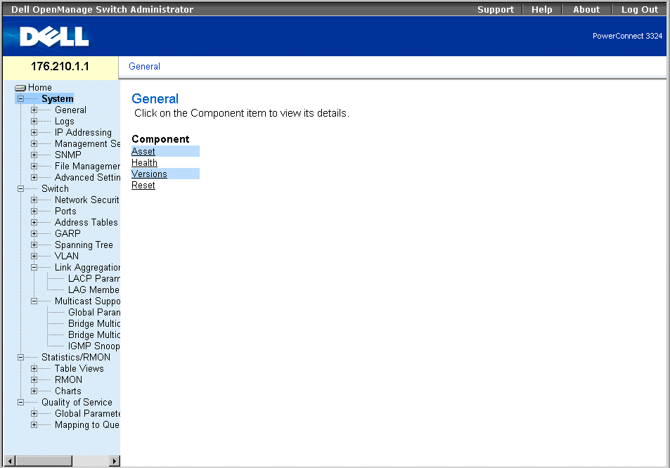
General Page
Viewing the Asset Page
The Asset page contains parameters for configuring general device information, including the system name, location, and contact, the system MAC Address, System Object ID, date, time, and System Up Time. To open the Asset page:
- Click System > General > Asset in the Tree View. The Asset page opens.
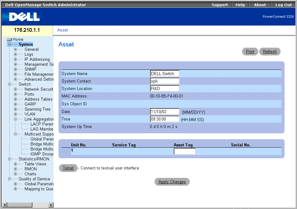
Asset Page
The Asset page contains the following fields:
- System Name—Defines the user-defined device name.
- System Contact—Specifies the name of the contact person.
- System Location—Indicates the location where the system is currently running.
- MAC Address—Specifies the switch MAC address.
- Sys Object ID—Identifies the OID of the MIB.
- Date (MM/DD/YY)—Indicates the current date. The format is month, day, year; for example, 11/10/02 is November 10, 2002.
- Time (HH:MM:SS)—Specifies the time. The format is hour, minute, second; for example, 20:12:03 is twelve minutes and three seconds past eight in the evening.
- System Up Time—Specifies the amount of time since the last device reset. The system time is displayed in the following format: Day, Hour Minutes, and Seconds. For example, 41 days 2 hours 22 minutes 15 seconds.
- Unit No.—Indicates the stacking unit number.
- Service Tag—Indicates the service reference number used when servicing the device.
- Asset Tag—Specifies the user-defined device reference.
- Serial No.—Indicates the serial number of the device.
Defining system information:
- Open the Asset page.
- Define the System Name, System Contact, System Location, Date, Asset Tag, and
Time fields.
- Click Apply Changes. The system parameters are defined, and the device is updated.
Initiating a Telnet Session:
- Open the Asset page.
- Click Telnet. A Telnet session is initiated.
Configuring Device Information Using the CLI Commands
The following table summarizes the equivalent CLI commands for viewing fields displayed in the Asset page.
|
CLI Command
|
Description
|
|---|
hostname name | Specifies or modifies the device host name. |
snmp-server contact text | Sets up a system contact. |
snmp-server location text | Enters information on where the device is located. |
clock set hh:mm:ss day month year | Manually sets the system clock and date. Note the different date format. |
show clock | Displays the time and date from the system clock. |
show system id | Displays the service tag information. |
show system | Displays system information. |
asset tag | Displays the device asset tag. |
The following is an example of the CLI commands:
Console (config)# hostname dell
Console (config)# snmp-server contact Dell_Tech_Supp
Console (config)# snmp-server location New_York
Console (config)# exit
Console # exit
Console (config)# asset-tag lqwepot
Console> clock set 13:32:00 7 Mar 2002
Console> show clock
13:32:00 7 Mar 2002
console# show system
System Description: Ethernet Stackable
Switching System
System Up Time (days,hour:min:sec): 0,00:30:58
System Contact: Dell_Tech_Supp
System Name: dell
System Location: New_York
MAC Address: 00:00:b0:22:33:44
Sys Object ID: 1.3.6.1.4.1.674.10895.3004
Power supply Source Status
------------------ --------------------- -------------
Internal Power Supply Internal redundant OK unit1
External Power Supply External OK unit1
Internal PowerSupply Internal redundant OK unit2
External PowerSupply External OK unit2
Internal PowerSupply Internal redundant OK unit3
External PowerSupply External OK unit3
Internal PowerSupply Internal redundant OK unit6
External PowerSupply External OK unit6
Viewing System Health Information
The System Health page physical device hardware information. To open the System Health page:
- Click System > General > Health in the Tree View. The System Health page opens.
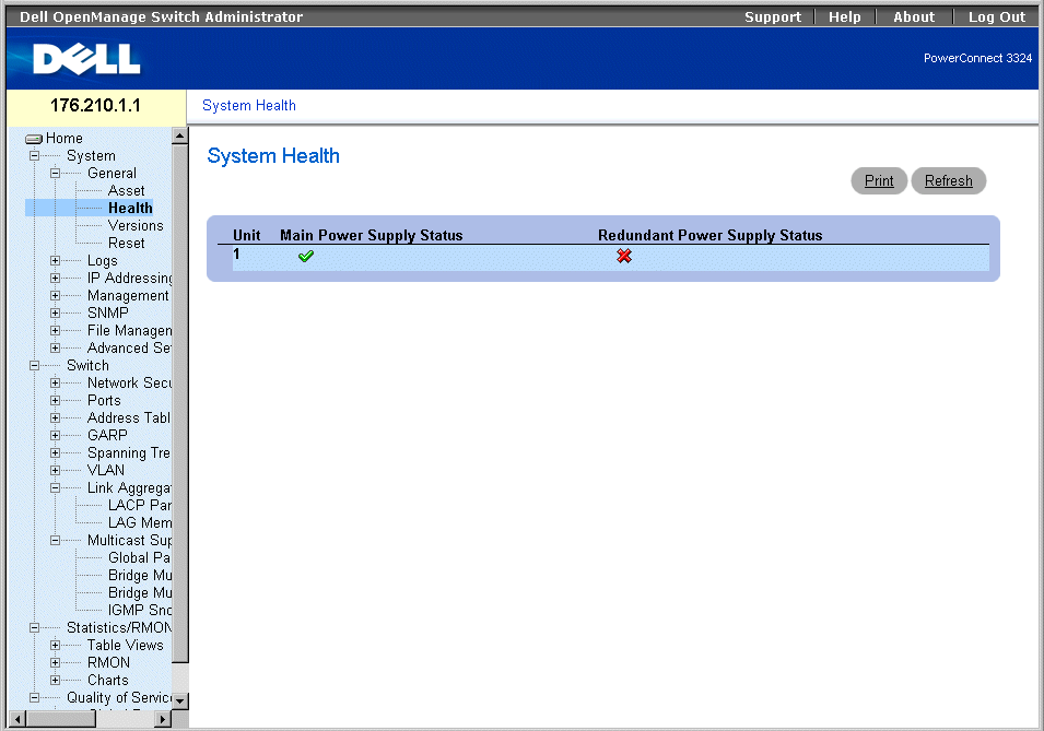
System Health Page
The System Health page contains the following fields:
- Unit—Indicates the stacking unit number.
- Main Power Supply Status—Indicates the main power supply state. The possible field values are:
 —Indicates the main power supply is operating normally for the specified unit.
 —Indicates the main power supply is not operating normally for the specified unit.
- Not Present—Indicates that the power supply is not present for the specified unit.
- Redundant Power Supply Status—Indicates the redundant power supply state. The possible field values are:
 —Indicates the redundant power supply is operating normally for the specified unit
 —Indicates the redundant power supply is not operating normally for the specified unit.
- Not Present—Indicates that the power supply is not present for the specified unit.
Viewing System Health Information Using the CLI Commands
The following table summarizes the equivalent CLI commands for viewing fields displayed in the System Health page.
|
CLI Command
|
Description
|
|---|
show system | Displays system information. |
The following is an example of the CLI commands:
Console> show system
System Description: Ethernet Stackable
Switching System
System Up Time (days,hour:min:sec): 0,00:08:56
System Contact: Dell_Tech_Supp
System Name: dell
System Location: New_York
Viewing the Versions Page
The Versions page contains information about the hardware and software versions currently running. To open the Versions page:
- Click System > General > Versions in the Tree View. The Versions page opens.
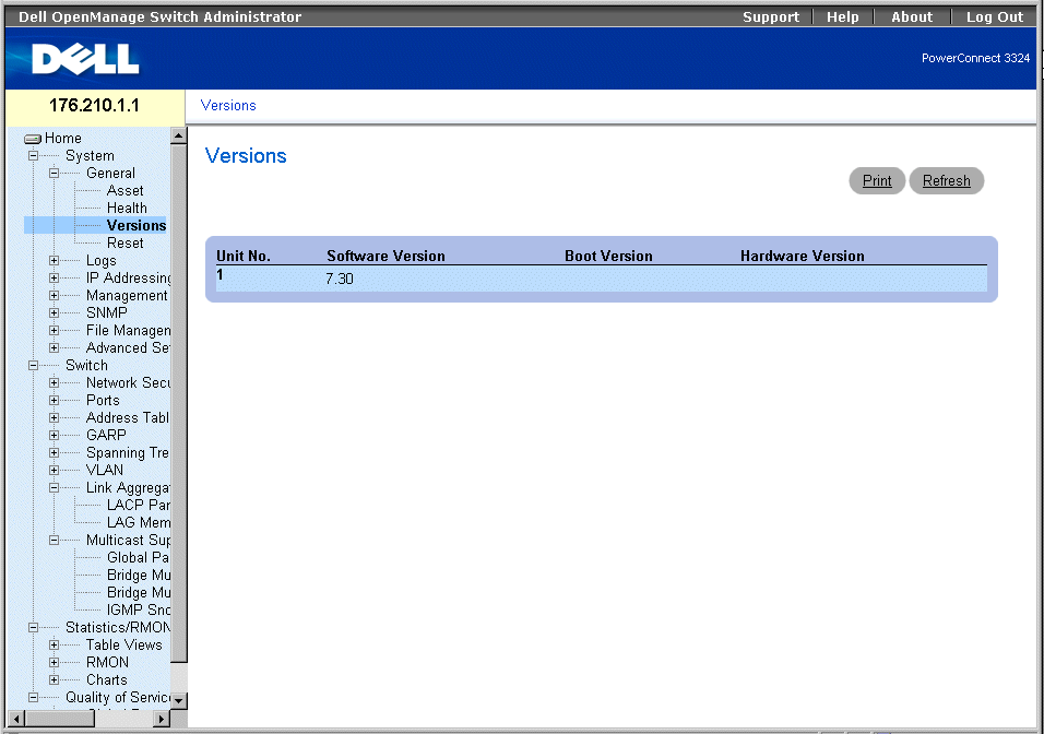
Versions Page
The Versions page contains the following information:
- Unit No.—Indicates the stacking unit number.
- Software Version—Displays the current software version running on a specific stacking unit.
- Boot Version—Displays the current Boot version running on a specific stacking unit.
- Hardware Version—Displays the current hardware versions running on a specific stacking unit.
Displaying Device Versions using the CLI
The following table summarizes the equivalent CLI commands for viewing fields displayed in the Versions page.
|
CLI Command
|
Description
|
|---|
show version | Displays the system version information. |
The following is an example of the CLI commands:
Console> show version
SW version 1.0.0.01 (date 14-Feb-2003 time 14:42:16 )
Boot version 1.30.11 ( date 27-Jan-2003 time 10:06:02 )
HW version 01.01.01
Resetting the Device
The Reset page allows users to reset the device from a remote location. To open the Reset page:
- Click System > General > Reset in the Tree View. The Reset page opens.
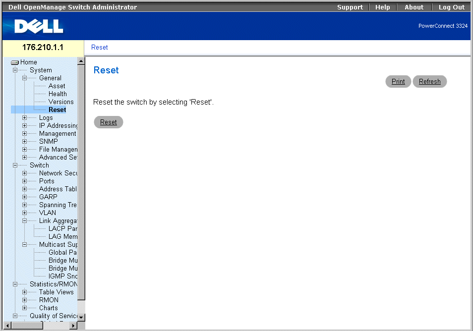
Reset Page
 |
NOTE: Save all changes to the Running Configuration file before resetting the device to prevent
the current device configuration from being lost. For more information about saving
Configuration files, see "Managing Files".
|
Resetting the device:
- Open the Reset page.
- Click Reset. A confirmation message displays:
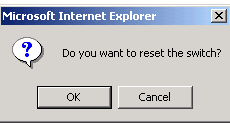
Device Reset Confirmation Message
- Click OK. The device is reset. After the device is reset, the user is prompted for a user
name and password.
Resetting the Device Using the CLI
The following table summarizes the equivalent CLI commands for viewing fields displayed in the Reset page.
|
CLI Command
|
Description
|
|---|
reload | Reloads the operating system. |
The following is an example of the CLI commands:
Console >reload
This command will reset the whole system and disconnect your
current
session. Do you want to continue (y/n) [n] ?
Managing Logs
The Logs page contains links to various log pages. To open the Logs page:
- Click System > Logs in the Tree View. The Logs page opens.
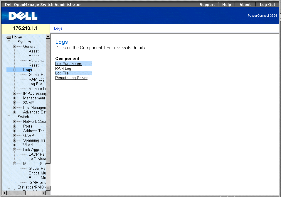
Logs Page
The Logs page contains links to the following pages:
Defining Global Log Parameters
The System Logs enable you to view significant events in real time and keep a record of these events for later use. This feature provides the ability to log and manage events and report errors.
Event messages have a unique format, as per the SYSLOG RFC recommended message format for all error reporting; for example, Syslog+ local device reporting. Messages are assigned a severity code and include a message mnemonic, which identifies the source application generating the message. Messages are filtered based on their urgency or relevancy. The severity of each message determines the set of event logging devices to which messages are sent for each event logging device. The following table contains the Log Severity Levels:
|
Severity Type
|
Severity Level
|
Description
|
|---|
Emergency | 0 | Indicates that the system is not functioning. |
Alert | 1 | Indicates that the system needs immediate attention. |
Critical | 2 | Indicates that the system is in a critical state. |
Error | 3 | Indicates that a system error has occurred. |
Warning | 4 | Indicates that a system warning has occurred. |
Notice | 5 | Indicates that the system is functioning properly, but system notice has occurred. |
Informational | 6 | Provides device information. |
Debug | 7 | Provides detailed information about the log. |
Log Severity Levels
The Global Log Parameters page enables you to define which events are recorded to which logs. It contains fields for enabling logs globally and parameters for defining log parameters. The Severity log messages are listed from the highest to the lowest severity. To open the Global Log Parameters page:
- Click System > Logs > Global Parameters in the Tree View. The Global Log Parameters page opens.
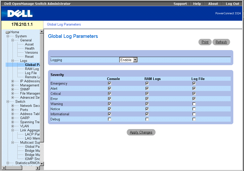
Global Log Parameters Page
The Global Log Parameters page contains the following fields:
- Logging—Enables device global logs for Cache, File, and Server Logs. Console logs are enabled by default and cannot be disabled. The possible field values are:
- Enable—Enables saving logs in Cache (RAM), File (FLASH), and an External Server.
- Disable—Disables saving logs. Console logs cannot be disabled.
- Severity—The following are the available severity logs:
- Emergency—Indicates the highest warning level. If the device is down or not functioning properly, an emergency log message is saved to the specified logging location.
- Alert—Indicates the second highest warning level. An alert log is saved if there is a serious device malfunction; for example, if all device features are down.
- Critical—Indicates the third-highest warning level. A critical log is saved when a critical device malfunction occurs; for example, if two device ports are not functioning while the rest of the device ports remain functional.
- Error—Indicates that a device error has occurred; for example, if a single port is offline.
- Warning—Indicates the lowest level of a device warning. The device is functioning, but an operational problem has occurred.
- Notice—Provides the network administrators with device information.
- Informational—Provides device information.
- Debug—Provides detailed information about the log. If a Debug error occurs, contact Dell Online Technical Support (www.support.dell.com).
 |
NOTE: When a severity level is selected, all severity level choices above the selection are
selected automatically.
|
The Global Log Parameters page also contains check boxes that correspond to a distinct logging system:
- Console—Indicates the minimum severity level from which logs are sent to the console.
- RAM Logs—Indicates the minimum severity level from which logs are sent to the Log File kept in RAM (Cache).
- Log File—Indicates the minimum severity level from which logs are sent to the Log File kept in FLASH memory.
Enabling Logs:
- Open the Global Log Parameters page.
- Select Enable in the Logging drop-down list.
- Select the log type and log severity in the Global Log Parameters check boxes.
- Click Apply Changes. The log settings are saved, and the device is updated.
Enabling Logs Using CLI Commands
The following table summarizes the equivalent CLI commands for viewing fields displayed in the Global Log Parameters page.
|
CLI Command
|
Description
|
|---|
logging on | Enables error message logging. |
logging ip-address [port port] [severity level] [facility facility] [description text] | Logs messages to a syslog server. For a list of the Severity levels, see "Log Severity Levels". |
logging console level | Limits messages logged to the console based on severity. |
logging buffered level | Limits syslog messages displayed from an internal buffer (RAM) based on severity. |
logging file level | Limits syslog messages sent to the logging file based on severity. |
clear logging | Clears logs. |
The following is an example of the CLI commands:
Console (config)# logging on
Console (config)# logging console errors
Console (config)# logging buffered debugging
Console (config)# logging file alerts
Console (config)# clear logging
Displaying RAM Log Table
The RAM Log Table contains information about log entries kept in RAM, including the time the log was entered, the log severity, and a description of the log. To open the RAM Log Table page:
- Click System > Logs> RAM Log in the Tree View. The RAM Log Table page opens.
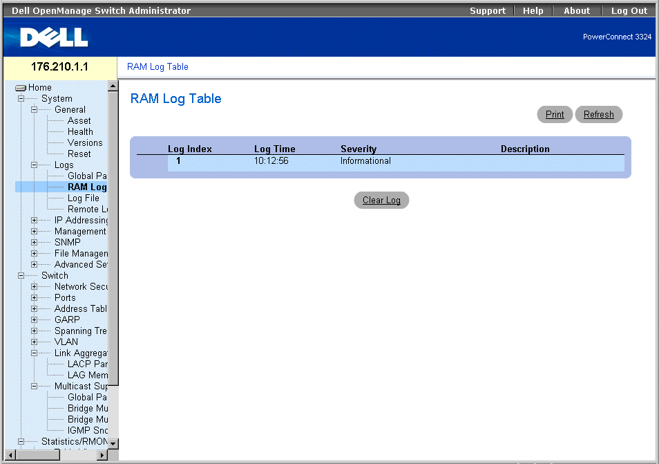
RAM Log Table Page
The RAM Log Table page contains the following fields:
- Log Index—Indicates the log number in the RAM Log Table.
- Log Time—Specifies the time at which the log was entered in the RAM Log Table.
- Severity—Specifies the log severity.
- Description—Displays the user-defined log description.
Removing Log Information:
- Open the RAM Log Table page.
- Click Clear Log. The log information is removed from the RAM Log Table/Log File
Table, and the device is updated.
Viewing the RAM Log Table Using the CLI Commands
The following table summarizes the equivalent CLI commands for viewing fields displayed in the RAM Log Table page.
|
CLI Command
|
Description
|
|---|
show logging | Displays the state of logging and the syslog messages stored in the internal buffer. |
clear logging | Clears logs. |
The following is an example of the CLI commands:
Console # show logging
Console logging: level debugging. Console Messages: 0 Dropped
(severity).
Buffer logging: level debugging. Buffer Messages: 11 Logged, 200
Max.
File logging: level notifications. File Messages: 0 Dropped
(severity).
Syslog server 192.180.2.27 logging: errors. Messages: 6 Dropped
(severity).
Syslog server 192.180.2.28 logging: errors. Messages: 6 Dropped
(severity).
2 messages were not logged (resources)
Buffer log:
11-Aug-2002 15:41:43: %LINK-3-UPDOWN: Interface FastEthernet0/0,
changed state to up
11-Aug-2002 15:41:43: %LINK-3-UPDOWN: Interface Ethernet1/e0,
changed state to up
11-Aug-2002 15:41:43: %LINK-3-UPDOWN: Interface Ethernet1/e1,
changed state to up
11-Aug-2002 15:41:43: %LINK-3-UPDOWN: Interface Ethernet1/e2,
changed state to up
11-Aug-2002 15:41:43: %LINK-3-UPDOWN: Interface Ethernet1/e3,
changed state to up
11-Aug-2002 15:41:43: %SYS-5-CONFIG_I: Configured from memory by
console
11-Aug-2002 15:41:39: %LINEPROTO-5-UPDOWN: Line protocol on
Interface FastEthernet0/0, changed state to up
11-Aug-2002 15:41:39: %LINEPROTO-5-UPDOWN: Line protocol on
Interface Ethernet1/e0, changed state to down
11-Aug-2002 15:41:39: %LINEPROTO-5-UPDOWN: Line protocol on
Interface Ethernet1/e1, changed state to down
11-Aug-2002 15:41:39: %LINEPROTO-5-UPDOWN: Line protocol on
Interface Ethernet1/e2, changed state to down
11-Aug-2002 15:41:39: %LINEPROTO-5-UPDOWN: Line protocol on
Interface Ethernet1/e3, changed state to down
Console # clear logging
clear logging buffer [confirm]
Console #
Console # clear logging file
clear logging buffer [confirm]
Console #
Displaying the Log File Table
The Log File Table contains information about log entries saved to the Log File in FLASH, including the time the log was entered, the log severity, and a description of the log message. To open the Log File Table page:
- Click System > Logs > Log File in the Tree View. The Log File Table page opens.
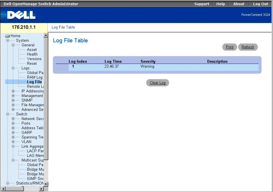
Log File Table
The Log File Table contains the following fields:
- Log Index—Indicates the log number in the Log File Table.
- Log Time—Specifies the time at which the log was entered in the Log File Table .
- Severity—Specifies the log severity.
- Description—Displays the log message text.
Displaying the Log File Table Using the CLI Commands
The following table summarizes the equivalent CLI commands for viewing fields displayed in the Log File Table.
|
CLI Command
|
Description
|
|---|
show logging file | Displays the state of logging and the syslog messages stored in the logging file. |
clear logging | Clears all log files. |
The following is an example of the CLI commands:
Console # show logging file
Console logging: level debugging. Console Messages: 0 Dropped
(severity).
Buffer logging: level debugging. Buffer Messages: 11 Logged, 200
Max.
File logging: level notifications. File Messages: 0 Dropped
(severity).
Syslog server 192.180.2.27 logging: errors. Messages: 6 Dropped
(severity).
Syslog server 192.180.2.28 logging: errors. Messages: 6 Dropped
(severity).
2 messages were not logged (resources)
File log:
11-Aug-2002 15:41:43: %LINK-3-UPDOWN: Interface FastEthernet0/0,
changed state to up
11-Aug-2002 15:41:43: %LINK-3-UPDOWN: Interface Ethernet1/e0,
changed state to up
11-Aug-2002 15:41:43: %LINK-3-UPDOWN: Interface Ethernet1/e1,
changed state to up
11-Aug-2002 15:41:43: %LINK-3-UPDOWN: Interface Ethernet1/e2,
changed state to up
11-Aug-2002 15:41:43: %LINK-3-UPDOWN: Interface Ethernet1/e3,
changed state to up
11-Aug-2002 15:41:43: %SYS-5-CONFIG_I: Configured from memory by
console
11-Aug-2002 15:41:39: %LINEPROTO-5-UPDOWN: Line protocol on
Interface FastEthernet0/0, changed state to up
11-Aug-2002 15:41:39: %LINEPROTO-5-UPDOWN: Line protocol on
Interface Ethernet1/e0, changed state to down
11-Aug-2002 15:41:39: %LINEPROTO-5-UPDOWN: Line protocol on
Interface Ethernet1/e1, changed state to down
11-Aug-2002 15:41:39: %LINEPROTO-5-UPDOWN: Line protocol on
Interface Ethernet1/e2, changed state to down
11-Aug-2002 15:41:39: %LINEPROTO-5-UPDOWN: Line protocol on
Interface Ethernet1/e3, changed state to down
Viewing the Remote Log Server Settings Page
The Remote Log Server Settings page contains fields for viewing the available Log Servers. In addition, new log servers can be defined and the severity of the logs sent to each server. To open the Remote Log Server Settings page:
- Click System > Logs > Remote Log Server in the Tree View. The Remote Log Server Settings page opens.
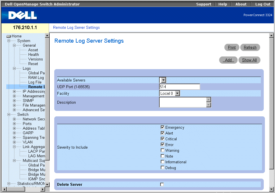
Remote Log Server Settings Page
The Remote Logs Server Settings page contains the following fields:
- Available Servers—Contains a list of servers to which logs can be sent.
- UDP Port (1-65535)—Indicates the UDP port to which the logs are sent for the selected server. The possible range is 1 - 65,535. The default value is 514.
- Facility—Indicates the facility mapping level for the selected server. The default value is Local 0. The possible values are:
- Local 0 - Local 7.
- No Map.
- Description—Displays the user-defined server description.
- Delete Server—Deletes the currently selected server from the Available Servers list. The possible field values are:
- Checked—Deletes the server from the Available Servers list.
- Unchecked—Maintains the server in the Available Servers list.
The Remote Logs Server Settings page also contains a severity list. The severity definitions are the same as the severity definitions on the "Global Log Parameters Page".
Sending logs to a server:
- Open the Remote Logs Server Settings page.
- Select a server from the Available Servers drop-down list.
- Define the UDP Port, Facility, and Description fields.
- Select the log severity in the Severity to Include check boxes.
- Click Apply Changes. The log settings are saved, and the device is updated.
Defining a new server:
- Open the Remote Logs Server Settings page.
- Click Add. The Add a Log Server page opens.
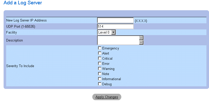
Add a Log Server Page
In addition to the fields in the Remote Logs Server Settings page, the Add a Log Server page contains the following field:
- New Log Server IP Address—Specifies the IP address of the new Log Server.
To add a log server:
- Define the New Log Server IP Address, UDP Port, Facility, and Description fields,
and select the Severity to Include check boxes.
- Click Apply Changes. The server is defined and added to the Available Servers list.
Displaying the Log Servers Table:
- Open the Remote Logs Server Settings page.
- Click Show All. The Log Servers Table page opens.

Log Servers Table Page
Removing a Log Server from the Log Servers Table page:
- Open the Remote Logs Server Settings page.
- Click Show All. The Log Servers Table page opens.
- Select a Log Servers Table entry.
- Check the Remove check box to remove the server(s).
- Click Apply Changes. The Log Servers Table entry is removed and the device is
updated.
Defining Device IP Addresses
The IP Addressing page contains links for assigning interface and default gateway IP addresses and defining ARP and DHCP parameters for the interfaces. To open the IP Addressing page:
- Click System > IP Addressing in the Tree View. The IP Addressing page opens.
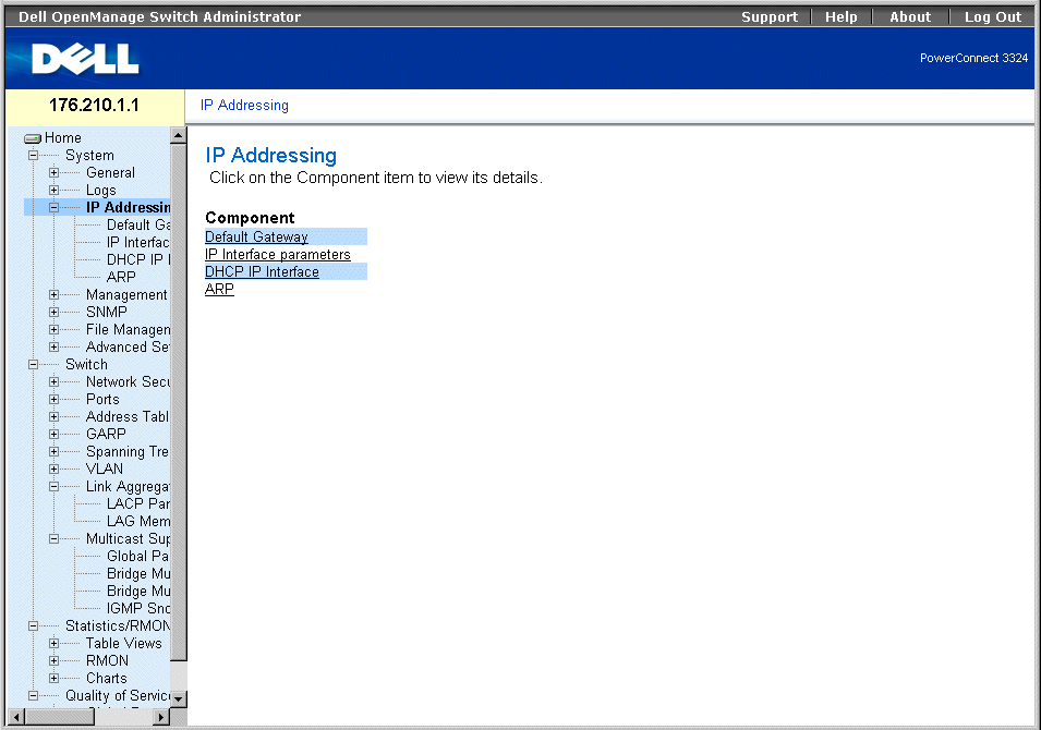
IP Addressing Page
The IP Addressing page contains links to the following pages:
Defining Default Gateways
The Default Gateway page allows network managers to assign Gateway devices. Packets are forwarded to the default IP when frames are sent to a remote network. The configured IP address must belong to the same IP address subnet of one of the IP interfaces. To open the Default Gateway page:
- Click System > IP Addressing > Default Gateway in the Tree View. The Default Gateway page opens.
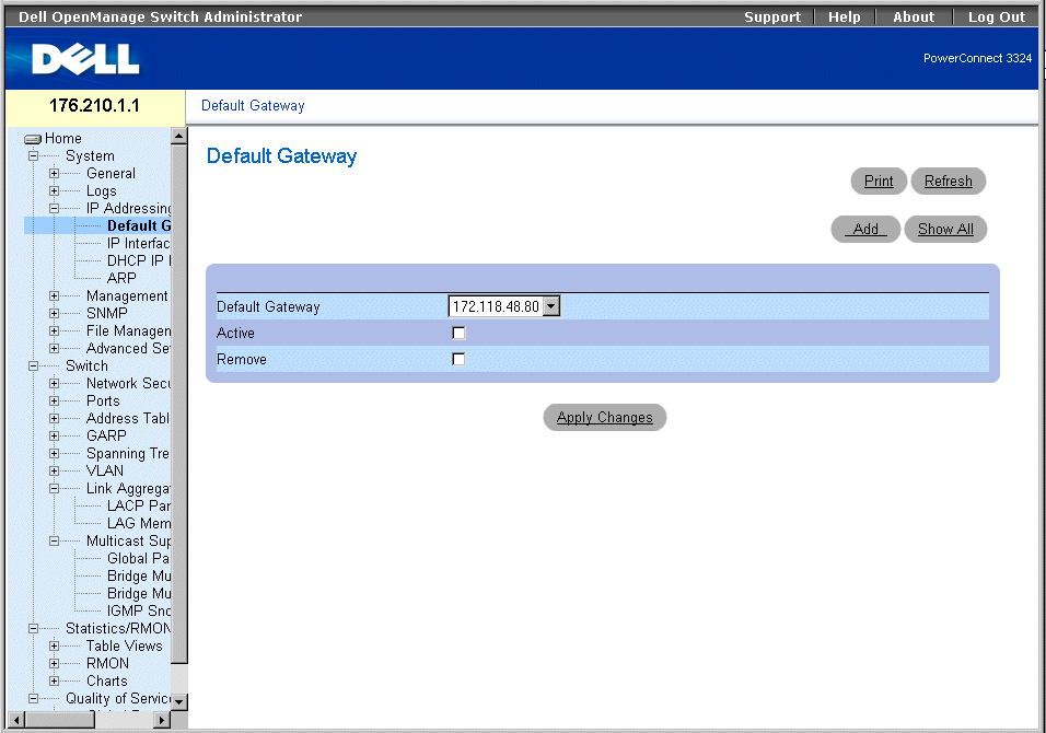
Default Gateway Page
The Default Gateway page contains the following fields:
- Default Gateway—Indicates the Gateway device IP address.
- Active—Indicates if the default Gateway device specified in the Default Gateway drop-down list is currently active. The possible field values are:
- Checked—Indicates the Gateway device is currently active.
- Unchecked—Indicates the Gateway device is not currently active.
- Remove—Removes Gateway devices from the Default Gateway drop-down list.
- Checked—Removes the selected Gateway devices from the Default Gateway drop-down list.
- Unchecked—Maintains Gateway devices in the Default Gateway drop-down list.
Selecting a Gateway device:
- Open the Default Gateway page.
- Select an IP address in the Default Gateway drop-down list.
- Check the Active check box.
- Click Apply Changes. The Gateway device is selected, and its status displays in the
Active field.
Adding a Gateway device:
- Open the Default Gateway page.
- Click Add. The Add New Default Gateway page opens.
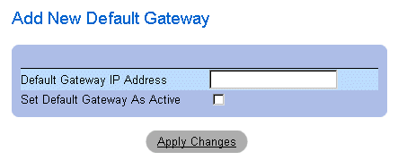
Add New Default Gateway
- Define the Default Gateway IP Address field.
OR
Set the new gateway as active by checking the check box.
- Click Apply Changes. The new default Gateway device is defined, and the device is
updated.
Displaying the Default Gateway Table:
- Open the Default Gateway page.
- Click Show All. The Default Gateway Table opens.
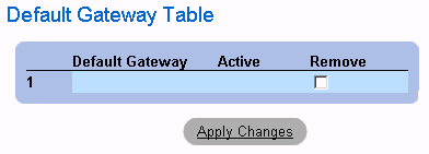
Default Gateway Table Page
Removing a Default Gateway device:
- Open the Default Gateway page.
- Click Show All. The Default Gateway Table page opens.
- Select a Default Gateway Table entry.
- Check the Remove check box to remove default gateways.
- Click Apply Changes. The Default Gateway Table entry is removed, and the device is
updated.
Defining Gateway devices Using the CLI Commands
The following table summarizes the equivalent CLI commands for viewing fields displayed in the Default Gateway page.
|
CLI Command
|
Description
|
|---|
ip default-gateway ip-address1 [ip-address2.] | Defines a default gateway. |
no ip default-gateway [ip-address] | Removes a default gateway. |
The following is an example of the CLI commands:
Console (config)# ip default-gateway 196.210.10.1
Console (config)# no ip default-gateway 196.210.10.1
Defining IP Interfaces
The IP Interface Parameters page contains parameters for assigning IP addresses to interfaces. To open the IP Interface Parameters page:
- Click System > IP Addressing > IP Interface Parameters in the Tree View. The IP Interface Parameters page opens.
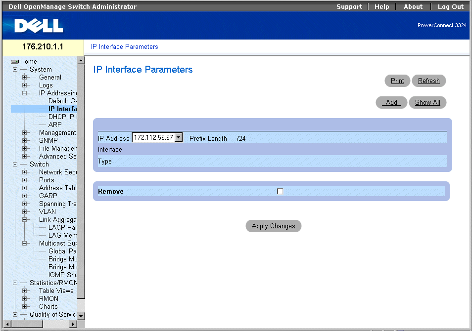
IP Interface Parameters Page
The IP Interface Parameters page contains the following fields:
- IP Address—Indicates the list of interface IP address.
- Interface—Specifies the interface type for which the selected IP address is defined. The possible field values are:
- Port—Indicates that the IP address was assigned to a port.
- LAG—Indicates that the IP address was assigned to a Link Aggregated Group (LAG).
- VLAN—Indicates that the IP address was assigned to a VLAN.
- Type—Indicates whether the IP address was defined manually as a static IP address or automatically through DHCP.
- Remove—Removes the selected interface from the IP Address drop-down list.
- Checked—Removes the interface from the IP Address drop-down list.
- Unchecked—Maintains the interface in the IP Address drop-down list.
Adding an IP Interface:
- Open the IP Interface Parameters page.
- Click Add. The Add a Static IP Interface page opens:

Add A Static IP Interface Page
- Define the IP Address, Interface, Network Mask, or the Prefix Length fields.
- Select the interface to which the IP interface will be assigned.
- Click Apply Changes. The new interface is added, and the device is updated.
Displaying the IP Interface Table:
- Open the IP Interface Parameters page.
- Click Show All. The IP Interface Table page opens. The IP Interface Table contains
the same fields as the "Defining IP Interfaces".
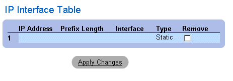
IP Interface Table Page
Deleting IP addresses:
- Open the IP Interface page.
- Click Show All. The IP Interface Table page opens.
- Select an entry in the IP Interface Table.
- Check the Remove check box to remove IP addresses.
- Click Apply Changes. The IP address is deleted, and the device is updated.
Defining IP Interfaces Using CLI Commands
The following table summarizes the equivalent CLI commands for viewing fields displayed in the IP Interface Parameters page.
|
CLI Command
|
Description
|
|---|
ip address ip-address {mask | prefix-length} | Sets an IP address. |
no ip address [ip-address] | Removes an IP address |
show ip interface [ethernet interface-number | vlan vlan-id | port-channel number] | Displays the usability status of interfaces configured for IP. |
The following is an example of the CLI commands:
Console (config)# interface vlan 1
Console (config-if)# ip address 131.108.1.27 255.255.255.0
Console (config-if)# no ip address 131.108.1.27
Console (config-if)# exit
Console# show ip interface vlan 1
Internet address is 10.7.1.192/24
console# show ip interface vlan 204
IP Address Directed Broadcast
----------------------- --------------------
146.1.0.132/29 disable
console#
Defining DHCP IP Interfaces
The DCHP IP Interface page specifies the DCHP client setting for the device per interface.
- Click System > IP Addressing > DHCP IP Interface in the Tree View. The DCHP IP Interface page opens.
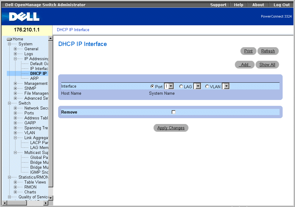
DHCP IP Interface Page
The DCHP IP Interface page contains the following fields:
- Interface—Select an interface of the device.
- Port—Specifies the interface type is a port, and the specific port number for which DHCP client settings are shown.
- LAG—Specifies the interface type is a LAG, and the specific LAG number for which DHCP client settings are shown.
- VLAN—Specifies the interface type is a VLAN, and the specific VLAN number for which DHCP client settings are shown.
- Host Name—Indicates the system name.
- Remove—Removes the DHCP client instance on the selected interface from the DHCP IP Interfaces Table.
- Checked—Removes the interface from the DHCP IP Interfaces Table.
- Unchecked—Maintains the interface in the DHCP IP Interfaces Table.
Adding a DCHP IP Interface:
- Open the DHCP IP Interface page.
- Click Add. The Add DHCP IP Interfaces page opens.
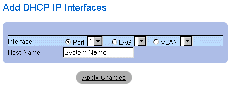
Add DHCP IP Interfaces
- Select the Interface and define the Host Name.
- Click Apply Changes. The new DHCP IP Interface is added, and the device is
updated.
Modifying a DCHP IP Interface:
- Open the DHCP IP Interface page.
- Modify the Interface field.
- Click Apply Changes. The entry is modified, and the device is updated.
Displaying the DHCP IP Interfaces Table:
- Open the DHCP IP Interface page.
- Click Show All. The DHCP IP Interfaces Table Page opens.

DHCP IP Interfaces Table Page
Deleting a DHCP IP Interface:
- Open the DHCP IP Interface page.
- Click Show All. The DHCP IP Interfaces Table opens.
- Select a DHCP client entry.
- Check the Remove check box to remove DHCP client entries.
- Click Apply Changes. The DHCP IP Interfaces Table entries are deleted, and the
device is updated.
Defining DCHP Clients Using CLI Commands
The following table summarizes the equivalent CLI commands for viewing fields displayed in the DHCP IP Interface page.
|
CLI Command
|
Description
|
|---|
ip address-dhcp [hostname host-name] | Acquires an IP address on an ethernet interface from DHCP. |
The following is an example of the CLI commands:
Console (config)# interface ethernet 1/e8
Console (config-if)# ip address-dhcp hostname marketing
Configuring ARP
The Address Resolution Protocol (ARP) is a TCP/IP protocol that converts IP addresses into physical addresses. The static entries can be defined in the ARP Table. When static entries are defined, a permanent entry is entered and is used to translate IP address to MAC addresses. To open the ARP Settings page:
- Click System > IP Addressing > ARP in the Tree View. The ARP Settings page opens.
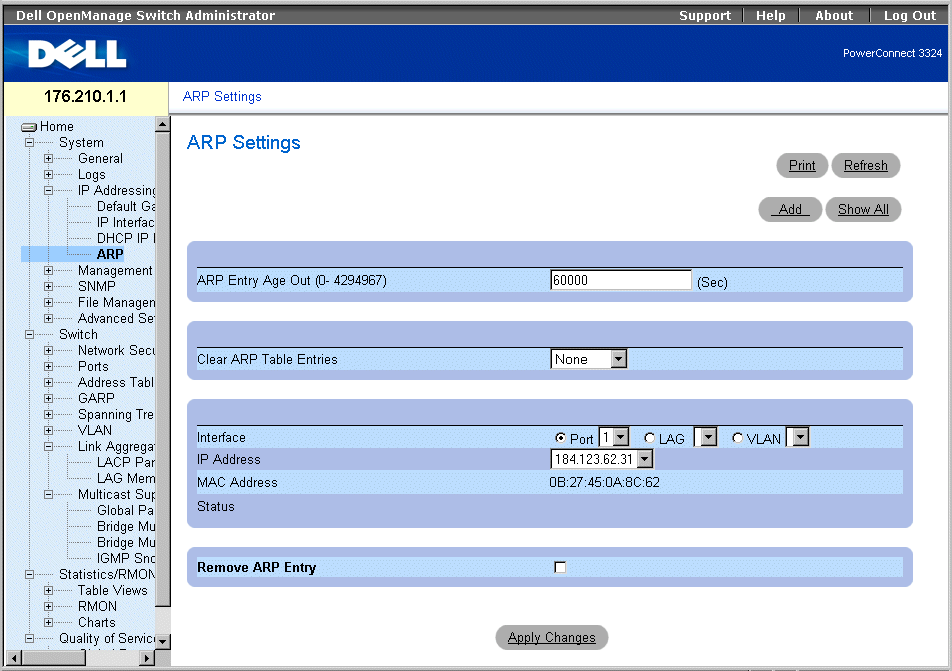
ARP Settings Page
The ARP Settings page contains the following fields:
- ARP Entry Age Out (0-4000000)—Indicates the amount of time (seconds) that passes before an ARP entry is aged out. After this period, the entry is deleted from the table. The default value is 60,000 seconds.
- Clear ARP Table Entries—Indicates the type of ARP entries that are cleared. The possible field values are:
- None—Indicates that ARP entries are not cleared.
- All—Indicates that all ARP entries are cleared.
- Static—Indicates that only static ARP entries are cleared.
- Dynamic—Indicates that only dynamic ARP entries are cleared.
- Interface—Select the interface type and the specific interface number. The possible field values:
- Port—Contains the port list for which ARP can be defined.
- LAG—Contains the LAG list for which ARP can be defined.
- VLAN—Contains the VLAN list for which ARP can be defined.
- IP Address—Select an IP address that is associated with the specified interface.
- MAC Address—Specifies the associated MAC address.
- Status—Specifies the status of the ARP Table entry. The possible field values are:
- Other—Indicates that the ARP entry is neither dynamically learned nor is it a static entry.
- Invalid—Indicates that the ARP entry is invalid.
- Dynamic—Indicates that the ARP entry was learned dynamically.
- Static—Indicates that the ARP entry is a static entry.
- Remove ARP Entry—Removes an ARP entry from the ARP Table.
- Checked—Removes a specific ARP entry.
- Unchecked—Maintains ARP entries.
Adding a static ARP Table entry:
- Open the ARP Settings page.
- Click Add. The Add ARP Entry page opens.
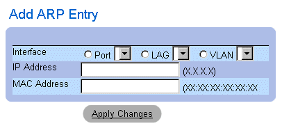
Add ARP Entry Page
- Select an Interface and define its IP Address and MAC address fields.
- Click Apply Changes. The ARP Table entry is added, and the device is updated.
Displaying the ARP Table:
- Open the ARP Setting page.
- Click Show All. The ARP Table page opens.

ARP Table Page
Deleting ARP Table entry:
- Open the ARP Setting page.
- Click Show All. The ARP Table page opens.
- Select a table entry.
- Check the Remove check box
- Click Apply Changes. The ARP Table entry is deleted, and the device is updated.
Configuring ARP Using the CLI Commands
The following table summarizes the equivalent CLI commands for viewing fields displayed in the ARP Settings page.
|
CLI Command
|
Description
|
|---|
arp ip_addr hw_addr {ethernet interface-number | vlan vlan-id | port-channel number} | Adds a permanent entry in the ARP cache. |
arp timeout seconds | Configures how long an entry remains in the ARP cache. |
show arp | Displays entries in the ARP Table. |
no arp | Removes an ARP entry from the ARP Table. |
The following is an example of the CLI commands:
console(config)# arp 146.1.0.131 00-00-55-66-77-00 ethernet 1/e1
Console (config)# exit
Console# arp timeout 12000
Console# show arp
Interface IP address HW address Status
---- ---------- ----------------- -------
1/e1 10.7.1.102 00:10:B5:04:DB:4B Dynamic
2/e2 10.7.1.135 00:50:22:00:2A:A4 Static
Managing Device Security
The Management Security page provides access to security pages that allow network administrators to set security parameters for ports, device management methods, user, and server security. To open the Management Security page:
- Click System >Management Security in the Tree View. The Management Security page opens.
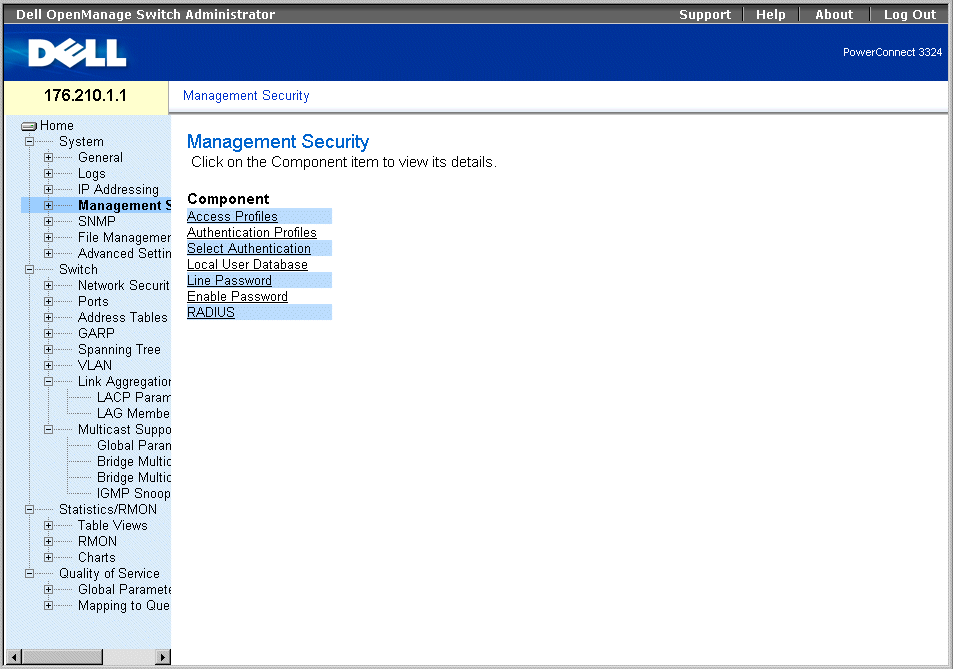
Management Security Page
This section includes the following topics:
Defining Access Profiles
The Access Profiles page allows network managers to define profiles and rules for accessing the device. Management method access can be limited to a specific user group by Ingress Ports, Source IP address, and/or Subnet Masks. Management Access methods can be separately defined for:
- Web Access (HTTP)
- Secure Web Access (HTTPS)
- Telnet
- SNMP
- All of the above
Users accessing one management service may differ from users managing a separate management service. Management Access Lists are comprised of rules that determine how the device is managed and by whom. To open the Access Profiles page:
- Click System > Management Security > Access Profiles in the Tree View. The Access Profiles page opens.
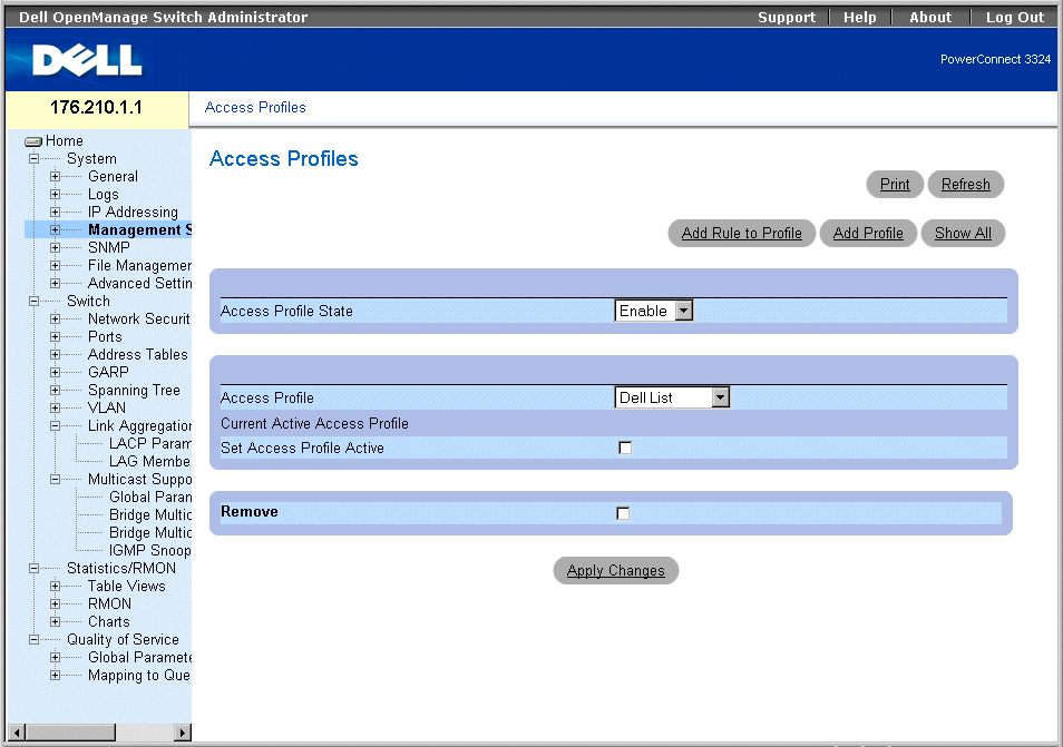
Access Profiles Page
The Access Profiles page contains the following fields:
- Access Profile State—Enables the Access Profile on the device. The possible field values are:
- Enable—Enables Access Profile Security Management on the device.
- Disable—Disables the Access Profile Security Management on the device. If Access Profile Security Management is disabled, the device is accessible to all stations.
- Access Profiles—Contains a list of user-defined Access Profile Lists. The Access Profile list contains the following default value:
- Console Only—Enables access only via the console. Selecting Console only disconnects HTTP and Telnet sessions. This is the default value, and cannot be removed.
- Current Active Access Profile —Displays the Access Profile that is currently active.
- Set Access Profile Active—Activates the selected Access Profile.
- Remove—Removes the selected Access Profile from the Access Profile Names.
- Checked—Removes an Access Profile.
- Unchecked—Maintains an Access Profile.
 |
NOTE: Active profiles cannot be removed.
|
Activating a Profile:
- Open the Access Profiles page.
- Select an Access Profile in the Access Profile field.
- Check the Set Access Profile Active check box.
- Click Apply Changes. The Access Profile is activated.
Adding an Access Profile:
Rules act as filters for determining rule priority, the device management method, interface type, source IP address and network mask, and the device management access action. Users can be blocked or permitted management access. Rule priority sets the order of rule application in a profile.
To define rules for an access profile:
- Open the Access Profiles page.
- Click Add Profile. The Add An Access Profile page opens.
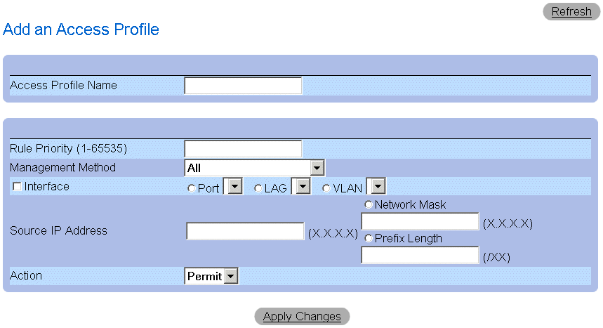
Add An Access Profile Page
The Add An Access Profile page contains the following fields:
- Access Profiles Name—Specifies the Access Profile for which rules are defined.
- Rule Priority (1-65535)—Indicates the rule priority (for an optional first rule to include in the new profile).
- Management Method—Specifies the management method for which the Access Profile is defined. The possible field values:
- All—Indicates all management methods are assigned to the Access Profile.
- Telnet—Indicates all Telnet sessions are assigned to the Access Profile.
- Secure Telnet—Indicates Secure Telnet sessions are assigned to the Access Profile.
- HTTP—Indicates HTTP sessions are assigned to the Access Profile.
- Secure HTTP—Indicates Secure HTTP sessions are assigned to the Access Profile.
- SNMP—Indicates SNMP sessions are assigned to the Access Profile.
- Interface—Specifies the interface to which the rule applies. The possible field values are:
- Port—Indicates the interface is a port, and the specific port for which the Access Profile is defined.
- LAG —Indicates the interface is a LAG, and the specific LAG for which the Access Profile is defined.
- VLAN—Indicates the interface is a VLAN, and the specific VLAN for which the Access Profile is defined.
- Source IP Address—Indicates the interface Source IP Address to which the packet is matched.
- Network Mask—Indicates the interface network mask to which the packet is matched.
- Prefix Length—Indicates the prefix length to which the packet is matched.
- Action—Defines the Management Security Rule action. The possible field values are:
- Permit—Permits management access to the defined interface.
- Deny—Denies management access to the defined interface.
- Define the Access Profile Name field.
- Define the Rule Priority, Management Method, Interface, Source IP, Network Mask,
Prefix Length, and Action fields.
- Click Apply Changes. The new Access Profile is added, and the device is updated.
Adding Rules to Access Profile:
 |
NOTE: The first rule must be defined to begin matching traffic to access profiles.
|
- Open the Access Profiles page.
- Click Add Rule to Profile. The Add An Access Profile Rule page opens.
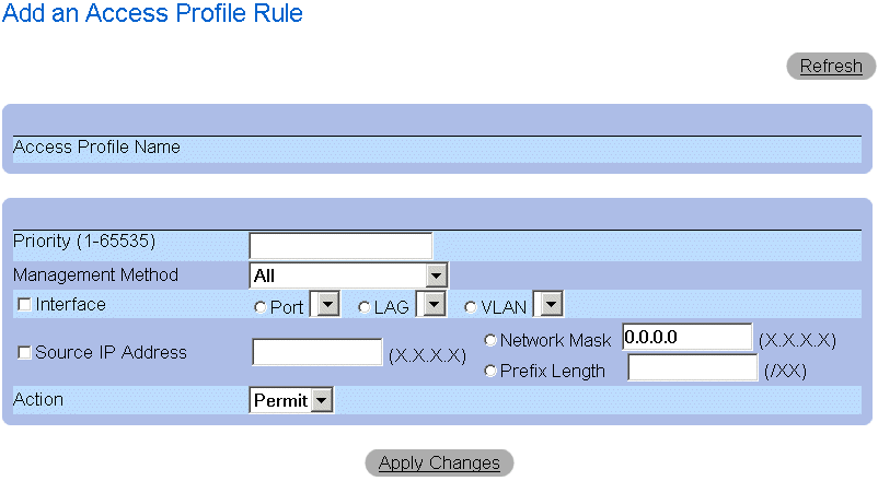
Add An Access Profile Rule Page
The Add An Access Profile Rule page contains the following fields:
- Access Profile Name—Indicates the name of the Access Profile.
- Rule Priority (1-65535)—Indicates the rule priority.
- Management Method—Specifies the management method for which the access profile is defined. The possible field values:
- All—Indicates all management methods are assigned to the Access Profile. Users with this Access Profile can access the device using all management methods.
- Telnet—Indicates all Telnet sessions are assigned to the Access Profile. Users with this Access Profile access the device using the Telnet management method.
- Secure Telnet—Indicates Secure Telnet sessions are assigned to the Access Profile. Users with this Access Profile access the device using the Secure Telnet management method.
- HTTP—Indicates HTTP sessions are assigned to the Access Profile. Users with this Access Profile access the device using the HTTP management method.
- Secure HTTP—Indicates Secure HTTP sessions are assigned to the Access Profile. Users with this Access Profile access the device using the Secure HTTP management method.
- SNMP—Indicates SNMP sessions are assigned to the Access Profile. Users with this Access Profile access the device using the SNMP management method.
- Interface—Specifies the interface to which the rule applies. The possible field values are:
- Port—Indicates the interface is a port, and the specific port for which the Access Profile is defined.
- LAG —Indicates the interface is a LAG, and the specific LAG for which the Access Profile is defined.
- VLAN—Indicates the interface is a VLAN, and the specific VLAN for which the Access Profile is defined.
- Source IP Address—Indicates the interface source IP address to which the packet is matched.
- Network Mask—Indicates the interface network mask to which the packet is matched.
- Prefix Length—Indicates the prefix length to which the packet is matched.
- Action—Defines the Management Security Rule action. The possible field values are:
- Permit—Permits management access to the defined interface.
- Deny—Denies management access to the defined interface.
- Define the Access Profile Name field.
- Define the Rule Priority, Management Method, Interface, Source IP, Network Mask,
Prefix Length, and Action fields.
- Click Apply Changes. The rule is added, and the device is updated.
Viewing the Profile Rules Table:
 |
NOTE: The order in which rules appear in the Profile Rules Table is important. Packets are
matched to the first rule which meets the rule criteria.
|
- Open the Access Profiles page.
- Click Show All.The Profile Rules Table page opens.
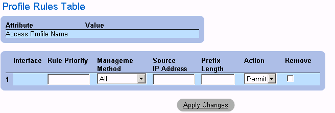
Profile Rules Table Page
- Click Apply Changes.
Removing a Rule:
 |
NOTE: When a rule is deleted, the profile name is also deleted.
|
- Open the Access Profiles page.
- Click Show All.The Profile Rules Table opens.
- Select a rule in the Profile Rules Table page.
- Check the Remove check box.
- Click Apply Changes. The rule is deleted, and the device is updated.
Defining Access Profiles Using CLI Commands
The following table summarizes the equivalent CLI commands for viewing fields displayed in the Access Profiles page.
|
CLI Command
|
Description
|
|---|
management access-list name | Defines an access-list for management, and enters the access-list context for configuration. |
permit [ethernet interface-number | vlan vlan-id | port-channel number] [service service] | Sets port permitting conditions for the management access list. |
permit ip-source ip-address [mask mask | prefix-length] [ethernet interface-number | vlan vlan-id | port-channel number] [service service] | Sets port permitting conditions for the management access list, and the selected management method. |
deny [ethernet interface-number | vlan vlan-id | port-channel number] [service service] | Sets port denying conditions for the management access list, and the selected management method. |
deny ip-source ip-address [mask mask | prefix-length] [ethernet interface-number | vlan vlan-id | port-channel number] [service service] | Sets port denying conditions for the management access list, and the selected management method. |
management access-class {console-only | name} | Defines which access-list is used as the active management connections. |
show management access-list [name] | Displays the active management access-lists. |
show management access-class | Displays information about management access-class. |
The following is an example of the CLI commands:
Console (config)# management access-list mlist
Console (config-macl)# permit ethernet 1/e1
Console (config-macl)# permit ethernet 2/e9
Console (config-macl)# deny ethernet 1/e2
Console (config-macl)# deny ethernet 2/e10
Console (config-macl)# exit
Console (config)# management access-class mlist
Console (config)# exit
Console# show management access-list
mlist
-----
permit ethernet 1/e1
permit ethernet 2/e9
! (Note: all other access implicitly denied)
Console> show management access-class
Management access-class is enabled, using access list mlist
Defining Authentication Profiles
The Authentication Profiles page allows network managers to select the user authentication method on the device. User authentication occurs:
- Locally
- Via an external server
User authentication can also be set to None.
User authentication occurs in the order the methods are selected. For example, if both the Local and RADIUS options are selected, the user is authenticated first locally. If the local user database is empty, the user is then authenticated via the RADIUS server.
If an error occurs during the authentication, the next selected method is used. To open the Authentication Profiles page:
- Click System > Management Security >Authentication Profiles in the Tree View. The Authentication Profiles page opens.
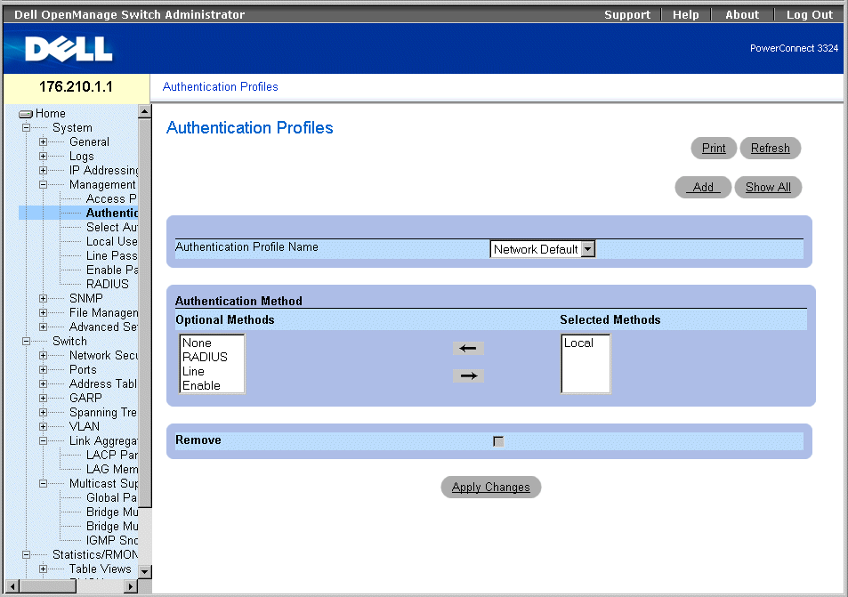
Authentication Profiles Page
The Authentication Profiles page contains the following options lists:
- Authentication Profile Name—Displays the user-defined authentication method lists and includes the following values:
- Network Default
- Console Default
- Optional Methods—Lists the user authentication methods. The possible options are:
- Local—Indicates that authentication occurs locally. The device checks the user name and password for authentication.
- None—Indicates that no user authentication occurs.
- RADIUS—Indicates that user authentication occurs in the RADIUS server.
- Line—Indicates that the line password is used for authentication.
- Enable—Indicates the enable password is used for authentication.
- Selected Methods—Indicates the selected authentication methods and their order.
- Remove—Removes the selected Authentication Profile from the Authentication Profile Name list.
- Checked—Removes an Authentication Profile.
- Unchecked—Maintains an Authentication Profile.
Selecting an Authentication Profile:
- Open the Authentication Profiles page.
- Select a profile in the Authentication Profile Name field.
- Select the authentication method using the arrow icons.
- Click Apply Changes. The user authentication profile is updated to the device.
Adding an Authentication Profile:
- Open the Authentication Profile page.
- Click Add. The Add Authentication Method Profile Name page opens.

Add Authentication Profile Page
Displaying the Show All Authentication Profiles Page:
- Open the Authentication Profiles page.
- Click Show All. The Open the Authentication Profile page opens:
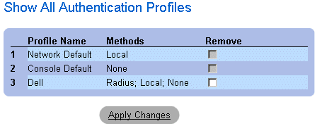
Authentication Profile Page
Deleting an Authentication Profile:
- Open the Authentication Profiles page.
- Click Show All. The Open the Authentication Profile page opens.
- Select an authentication profile.
- Check the Remove check box.
- Click Apply Changes. The authenticating profile is deleted.
Configuring an Authentication Profile Using CLI Commands
The following table summarizes the equivalent CLI commands for viewing fields displayed in the Authentication Profiles page.
|
CLI Command
|
Description
|
|---|
aaa authentication login {default | list-name} method1 [method2.] | Configures login authentication. |
no aaa authentication login {default | list-name | Removes a login authentication profile. |
The following is an example of the CLI commands:
Console (config)# aaa authentication login default radius local
enable none
Console (config)# no aaa authentication login default
Assigning Authentication Profiles
After Authentication Profiles are defined, the Authentication Profiles can be applied to Management Access methods. For example, console users can be authenticated by Authentication Method Lists 1, while Telnet users are authenticated by Authentication Method List 2. To open the Management Authentication page:
- Click System > Management Security > Select Authentication in the Tree View. The Select Authentication page opens.
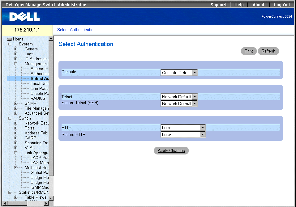
Select Authentication Page
The Select Authentication page contains the following fields:
- Console—Displays the Authentication Profiles used to authenticate console users. Authentication Profiles are assigned in the "Assigning Authentication Profiles". There are two predefined field values to which other Authentication Profiles can be added. However the predefined values cannot be deleted. The predefined field values are:
- Network Default
- Console Default
- Telnet—Displays the Authentication Profiles used to authenticate Telnet users. Authentication Profiles are assigned in Assigning Authentication Profiles. There are two predefined field values to which other Authentication Profiles can be added. However the predefined values cannot be deleted. The predefined field values are:
- Network Default
- Console Default
- Secure Telnet (SSH)—Displays the Authentication Profiles used to authenticate SSH users. Secure Shell (SSH) provides secure remote connections to a device. The SSH enables SSH clients to establish a secure, encrypted connection with a device. Authentication Methods Lists are assigned in the Assigning Authentication Profiles.
- HTTP—Displays the authentication methods used for HTTP access. The possible field values are:
- None—Indicates that no authentication profile is used for HTTP access.
- Local—Indicates that HTTP authentication occurs locally.
- Radius—Indicates that HTTP authentication occurs at the RADIUS server, and HTTP access is permitted.
- Local, None—Indicates that HTTP authentication first takes place locally. If no authentication method is used, the local user database is empty and HTTP access is permitted.
- Radius, None—Indicates that HTTP authentication first takes place at the RADIUS server. If no authentication method is used, the RADIUS server cannot be accessed.
- Local, Radius—Indicates that HTTP authentication first takes place locally. If the RADIUS server authenticates the user, the local user database is empty. If the RADIUS server cannot authenticate the management method, the HTTP session is blocked.
- Radius, Local—Indicates that HTTP authentication first takes place at the RADIUS server. If the RADIUS server cannot be accessed, the HTTP session is authenticated locally. If the HTTP session cannot be authenticated locally, the HTTP session is blocked.
- Local, Radius, None—Indicates that HTTP authentication first takes place locally. If the local database is empty, the RADIUS server authenticates the management method. If the RADIUS server cannot be accessed, the HTTP session is permitted.
- Radius, Local, None—Indicates that HTTP authentication first takes place at the RADIUS server. If the RADIUS server cannot be accessed, the HTTP session is authenticated locally. If the local database is empty, the HTTP session is permitted.
- Secure HTTP—Specifies the authentication profiles used for Secure HTTP access. The possible field values are:
- None—Indicates that no authentication profiles is used for Secure HTTP access.
- Local—Indicates that Secure HTTP authentication occurs locally.
- Radius—Indicates that Secure HTTP authentication occurs at the RADIUS server.
- Local, None—Indicates that Secure HTTP authentication first takes place locally. If the local database is empty, no authentication method is used, and secure HTTP access is permitted.
- Radius, None—Indicates that Secure HTTP authentication first takes place at the RADIUS server. If the RADIUS server cannot be accessed, no authentication method is used, and secure HTTP access is permitted.
- Local, Radius—Indicates that Secure HTTP authentication first takes place locally. If the local database is empty, the RADIUS server authenticates the user. If the RADIUS server cannot authenticate the management method, the Secure HTTP session is blocked.
- Radius, Local—Indicates that Secure HTTP authentication first takes place at the RADIUS server. If the RADIUS server cannot be accessed, the Secure HTTP session is authenticated locally. If the Secure HTTP session cannot be authenticated locally, the Secure HTTP session is blocked.
- Local, Radius, None—Indicates that Secure HTTP authentication first takes place locally. If the local database is empty, the RADIUS server authenticates the management method. If the RADIUS server cannot access the database, the Secure HTTP session is permitted.
- Radius, Local, None—Indicates that Secure HTTP authentication first takes place at the RADIUS server. If the RADIUS server cannot be accessed, the Secure HTTP session is authenticated locally. If the local database is empty, the Secure HTTP session is permitted.
Applying an Authentication List to Console Sessions:
- Open the Select Authentication page.
- Select an Authentication Profile in the Console field.
- Click Apply Changes. Console sessions are assigned an Authentication List.
Applying an Authentication Profile to Telnet Sessions:
- Open the Select Authentication page.
- Select an Authentication Profile in the Telnet field.
- Click Apply Changes. Telnet sessions are assigned an Authentication List.
Applying an Authentication Profile to Secure Telnet (SSH) Sessions:
- Open the Select Authentication page.
- Select an Authentication Profile in the Secure Telnet (SSH) field.
- Click Apply Changes. Secure Telnet (SSH) sessions are assigned an Authentication
Profile.
Assigning HTTP Sessions a Authentication Sequence:
- Open the Select Authentication page.
- Select an authentication sequence in the HTTP field.
- Click Apply Changes. HTTP sessions are assigned an authentication sequence.
Assigning Secure HTTP Sessions a Authentication Sequence:
- Open the Select Authentication page.
- Select an authentication sequence in the Secure HTTP field.
- Click Apply Changes. Secure HTTP sessions are assigned an authentication sequence.
Assigning Access Authentication Profiles or Sequences Using CLI Commands
The following table summarizes the equivalent CLI commands for viewing fields displayed in the Select Authentication page.
|
CLI Command
|
Description
|
|---|
enable authentication [default | list-name] | Specifies the authentication method list when accessing a higher privilege level from a remote Telnet or console. |
login authentication [default | list-name] | Specifies the login authentication method list for a remote Telnet or console. |
ip http authentication method1 [method2.] | Specifies authentication methods for http servers. |
ip https authentication method1 [method2.] | Specifies authentication methods for https servers. |
show authentication methods | Displays information about the authentication methods. |
The following is an example of the CLI commands:
Console (config-line)# enable authentication default
Console (config-line)# login authentication default
Console (config-line)# exit
Console (config)# ip http authentication radius local
Console (config)# ip https authentication radius local
Console (config)# exit
Console# show authentication methods
Login Authentication Method Lists
---------------------------------
Default: Radius, Local, Line
Console_Login: Line, None
Enable Authentication Method Lists
----------------------------------
Default: Radius, Enable
console> enable: Enable, None
Line Login Method List Enable Method List
------- ----------------- -------------------
Console Console_Login Console_Enable
Telnet Default Default
SSH Default Default
HTTP: Radius, local
HTTPS: Radius, local
Defining the Local User Databases
The Local User Database page allows network managers to define users, passwords and access levels. Password are limited to a maximum of 16 characters. To open the Local User Database page:
- Click System > Management Security > Local User Database in the Tree View. The Local User Database page opens.
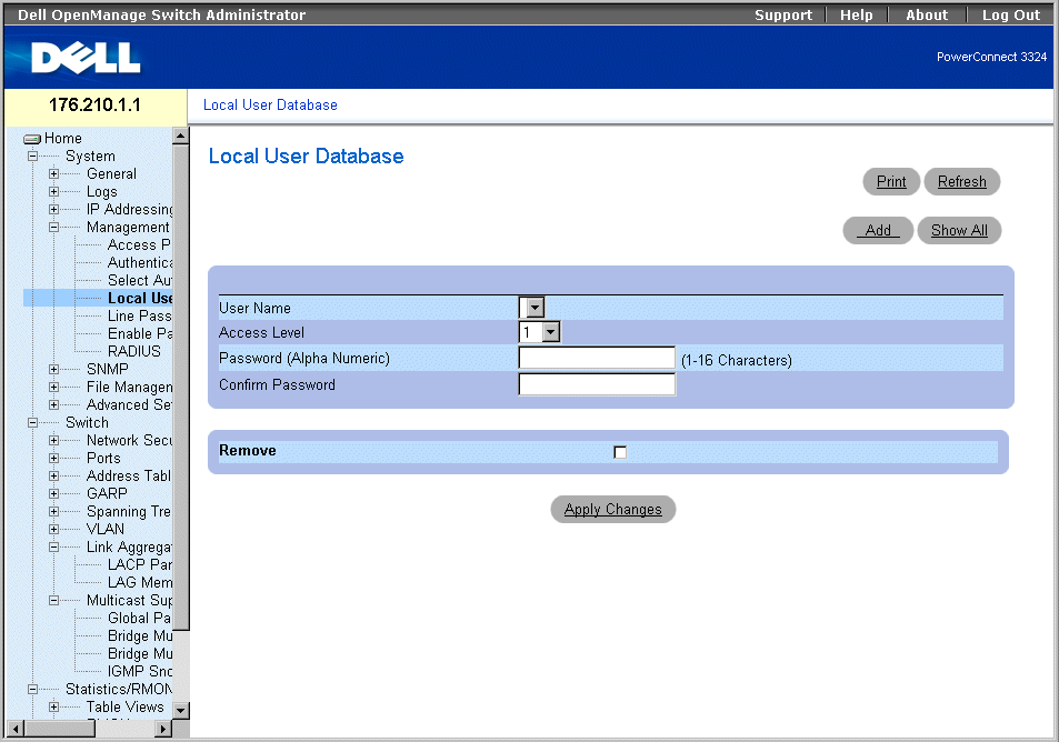
Local User Database Page
The Local User Database page contains the following fields:
- User Name—Contains a list of users.
- Access Level—Determines the user access level. The possible values are:
- 1-15—Indicates the user access level. 1 indicates the lowest user access level.
- Password (Alpha Numeric)—Specifies the user password. The password is displayed as *******.
- Confirm Password—Confirms the user-defined password. The confirmed password is displayed as *******.
- Remove—Removes users from the User Name list.
- Checked—Removes a specific user from the Local User Database.
- Unchecked—Maintains the user in the Local User Database .
Assigning access rights to a user:
- Open the Local User Database page.
- Select a user in the User Name field.
- Define the Access Level, and Password fields.
- Click Apply Changes. The user access rights and passwords are defined, and the
device is updated.
Defining a New User:
- Open the Local User Database page.
- Click Add. The Add User page opens:
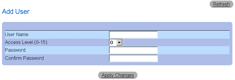
Add User Page
- Define a new user name in the User Name, Access Level (1-15), Password, and
Confirm Password fields.
- Click Apply Changes. The new user is defined, and the device is updated.
Displaying the Local User Table:
- Open the Local User Database page.
- Click Show All. The Local User Table page opens.
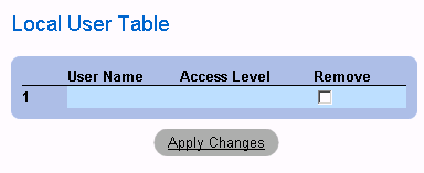
Local User Table Page
Deleting Users:
- Open the Local User Database page.
- Click Show All. The Local User Table page opens.
- Select a User Name.
- Check the Remove check box.
- Click Apply Changes. The user is deleted, and the device is updated.
Assigning Users Using CLI Commands
The following table summarizes the equivalent CLI commands for viewing fields displayed in the Local User Database page.
|
CLI Command
|
Description
|
|---|
username name [password password] [privilege level] [encrypted] | Establishes a username-based authentication system. |
The following is an example of the CLI commands:
Console (config)# username bob password lee privilege 15
Defining Line Passwords
The Line Passwords page allows network managers to define line passwords for management methods. Passwords are limit to maximum of 16 characters. To open the Line Passwords page:
- Click System > Management Security > Line Passwords in the Tree View. The Line Password page opens.
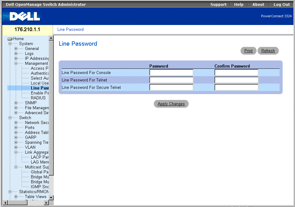
Line Password Page
The Line Password page contains the following fields:
- Line Password For Console—Specifies the line password for accessing the device via a console session. The password is displayed as *******.
- Line Password For Telnet—Specifies the line password for accessing the device via a Telnet session.The password is displayed as *******.
- Line Password For Secure Telnet—Specifies the Line Password for accessing the device via a Secure Telnet session. The password is displayed as *******.
Defining line passwords for console sessions:
- Open the Line Password page.
- Define the Line Password for Console field.
- Click Apply Changes. The line password for console sessions is defined, and the device
is updated.
Defining line passwords for Telnet sessions:
- Open the Line Password page.
- Define the Line Password for Telnet field.
- Click Apply Changes. The line password for the Telnet sessions is defined, and the
device is updated.
Defining line passwords for secure Telnet sessions:
- Open the Line Password page.
- Define the Line Password for Secure Telnet field.
- Click Apply Changes. The line password for Secure Telnet sessions is defined, and the
device is updated.
Assigning Line Passwords Using CLI Commands
The following table summarizes the equivalent CLI commands for viewing fields displayed in the Line Password page.
|
CLI Command
|
Description
|
|---|
password password [encrypted] | Specifies a password on a line. |
The following is an example of the CLI commands:
Console (config-line)# password dell
Defining Enable Password
The Modify Enable Password page sets a local password to control access to Normal, Privilege, and Global Configuration. To open the Modify Enable Password page.
- Click System > Management Security > Enable Passwords in the Tree View. The Modify Enable Password page opens.
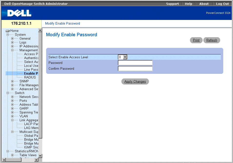
Modify Enable Password Page
The Modify Enable Password page contains the following fields:
- Select Enable Access Level—Specifies the access level associated with the Enable password.
- Password—Indicates the Enable password.The password is displayed as *******.
- Confirm Password—Confirms the new Enable password. The confirmed password is displayed as *******.
Defining a new Enable Password:
- Open the Modify Enable Password page.
- Define the Select Enable Access Level, Password, and Confirm Password fields.
- Click Apply Changes. The new Enable password is defined, and the device is updated.
Assigning Enable Passwords Using CLI Commands
The following table summarizes the equivalent CLI commands for viewing fields displayed in the Modify Enable Password page.
|
CLI Command
|
Description
|
|---|
enable password [level level] password [encrypted] | Sets a local password to control access to user and privilege levels. |
show users accounts | Displays information about the local user database. |
The following is an example of the CLI commands:
Console (config)# enable password level 15 dell
Console# show users accounts
Username Privilege
--------- ---------
Bob 15
Robert 15
Configuring RADIUS Global Parameters
Remote Authorization Dial-In User Service (RADIUS) servers provide additional security for networks. RADIUS servers provide a centralized authentication method for:
- Telnet Access
- Web Access
- Console to Switch Access
To open the RADIUS Settings page:
- Click System > Management Security >RADIUS in the Tree View. The RADIUS Settings page opens.
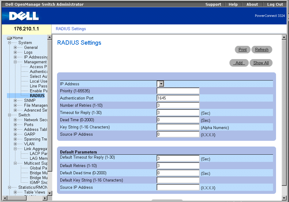
RADIUS Settings Page
The RADIUS Settings page contains the following fields:
- IP Address—Indicates the list of Authentication Server IP addresses.
- Priority (1-65535)—Indicates the server priority. The possible values are 1-65535, where 1 is the highest value. This is used to configure the order in which servers are queried.
- Authentication Port—Identifies the authentication port. The authentication port is used to verify the RADIUS server authentication.
- Number of Retries (1-10)—Specifies the number of transmitted requests sent to RADIUS server before a failure occurs. The possible field values are 1-10. Three is the default value
- Timeout for Reply (1-30)—Specifies the amount of the time in seconds the device waits for an answer from the RADIUS server before retrying the query or switching to the next server. The possible field values are 1-30. Three is the default value.
- Dead Time (0-2000)—Specifies the amount of time (in sec) that a RADIUS server is bypassed for service requests. The range is 0-2000.
- Key String (1-16 Characters)—Indicates the Key string used for authenticating and encrypting all RADIUS communications between the device and the RADIUS server. This key is encrypted.
- Source IP Address—Indicates the IP Address to use for the device accessing the RADIUS server.
The following fields set the RADIUS default values:
- Default Timeout for Reply (1-30)—Specifies the default amount of time (in seconds) the device waits for an answer from the RADIUS server before timing out.
 |
NOTE: If Host Specific Timeouts, Retransmit, Dead Time, or Deny values are not specified, the
Global values are applied to each host.
|
- Default Retries (1-10)—Specifies the default number of transmitted requests sent to RADIUS server before a failure occurs.
- Default Dead time (0-2000)—Specifies the default amount of time (in seconds) that a RADIUS server is bypassed for service requests. The range is 0-2000.
- Default Key String (1-16 Characters)—Indicates the Default Key string used for authenticating and encrypting all RADIUS communications between the device and the RADIUS server. This key is encrypted.
- Source IP Address—Indicates the default IP Address for the device accessing the RADIUS server.
Defining RADIUS Parameters:
- Open the RADIUS Settings page.
- Define the Default Timeout for Reply, Default Retries, Default Dead Time, and
Default Key Strings fields.
- Click Apply Changes. The RADIUS settings are updated to the device.
Adding a RADIUS Server:
- Open the RADIUS Settings page.
- Click Add. The Add RADIUS Settings page opens:
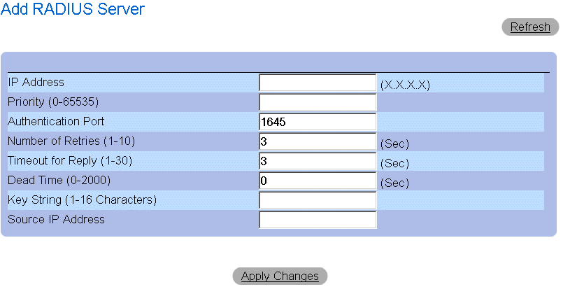
Add RADIUS Server Page
- Define the IP Address, Priority, Authentication Port, Number of Retries, Timeout for
Reply, Dead Time, Key String, and Source IP Address fields.
- Click Apply Changes. The new RADIUS server is added, and the device is updated.
Displaying the RADIUS Server List:
- Open the RADIUS Settings page.
- Click Show All. The RADIUS Servers List page opens.

RADIUS Servers List Page
Modifying the RADIUS Server settings:
- Open the RADIUS Settings page.
- Click Show All. The RADIUS Servers List page opens.
- Modify the Priority, Number of Retries, Timeout for Reply, or Dead Time fields.
- Click Apply Changes. The RADIUS Server settings are modified, and the device is
updated.
Deleting a RADIUS Server for the RADIUS Servers List:
- Open the RADIUS Settings page.
- Click Show All. The RADIUS Servers List page opens.
- Select a RADIUS Server in the RADIUS Servers List .
- Check the Remove check box. The RADIUS server is removed from the RADIUS
Servers List.
Defining RADIUS Servers Using CLI Commands
The following table summarizes the equivalent CLI commands for viewing fields displayed in the RADIUS Settings page.
|
CLI Command
|
Description
|
|---|
radius-server timeout timeout | Sets the default interval for which a device waits for a server host to reply. |
radius-server retransmit retries | Specifies the default number of times the software searches the list of RADIUS server hosts. |
radius-server deadtime deadtime | Configures unavailable default servers to be skipped. |
radius-server key key-string | Sets the default authentication and encryption key for all RADIUS communications between the device and the RADIUS environment. |
radius-server host ip-address [auth-port auth-port-number] [timeout timeout] [retransmit retries] [deadtime deadtime] [key key-string] [source source] [priority priority] | Specifies a RADIUS server host and any non-default settings. |
show radius-servers | Displays the RADIUS server settings. |
The following is an example of the CLI commands:
Console (config)# radius-server timeout 5
Console (config)# radius-server retransmit 5
Console (config)# radius-server deadtime 10
Console (config)# radius-server key dell-server
Console (config)# radius-server host 196.210.100.1 auth-port 1645
timeout 20
Console# show radius-servers
Port
IP address Auth Acct TimeOut Retransmit deadtime Priority
---------- ---- ---- ------- ---------- -------- --------
172.16.1.1 1645 1646 3 3 0 1
172.16.1.2 1645 1646 11 8 0 2
Defining SNMP Parameters
Simple Network Management Protocol (SNMP) provides a method for managing network devices. Devices supporting SNMP run a local software (agent).
The SNMP agents maintain a list of variables, which are used to manage the device. The variables are defined in the Management Information Base (MIB). The MIB presents the variables controlled by the agent. The SNMP protocol defines the MIB specification format as well as the format used to access the information over the network.
Access rights to the SNMP agents are controlled by access strings. To communicate with the device, the Embedded Web Server submits a valid community string for authentication. To open the SNMP page:
- Click System > SNMP in the Tree View. The SNMP page opens.
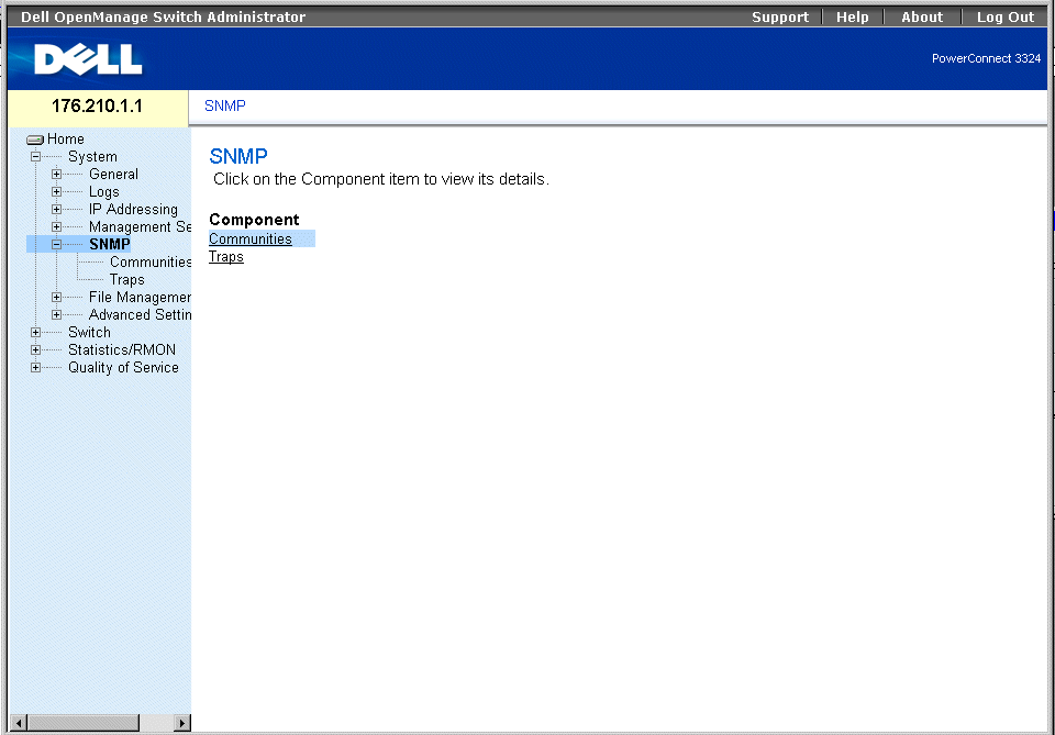
SNMP Page
This section contains information for managing the SNMP configuration, and includes the following topics:
Defining Communities
The system administrator manages access rights (read and write, read only, and so on.) by defining communities in the Community Table. When the community names are changed, access rights are also changed. To open the SNMP Community page:
- Click System > SNMP > Communities in the Tree View. The SNMP Community page opens.
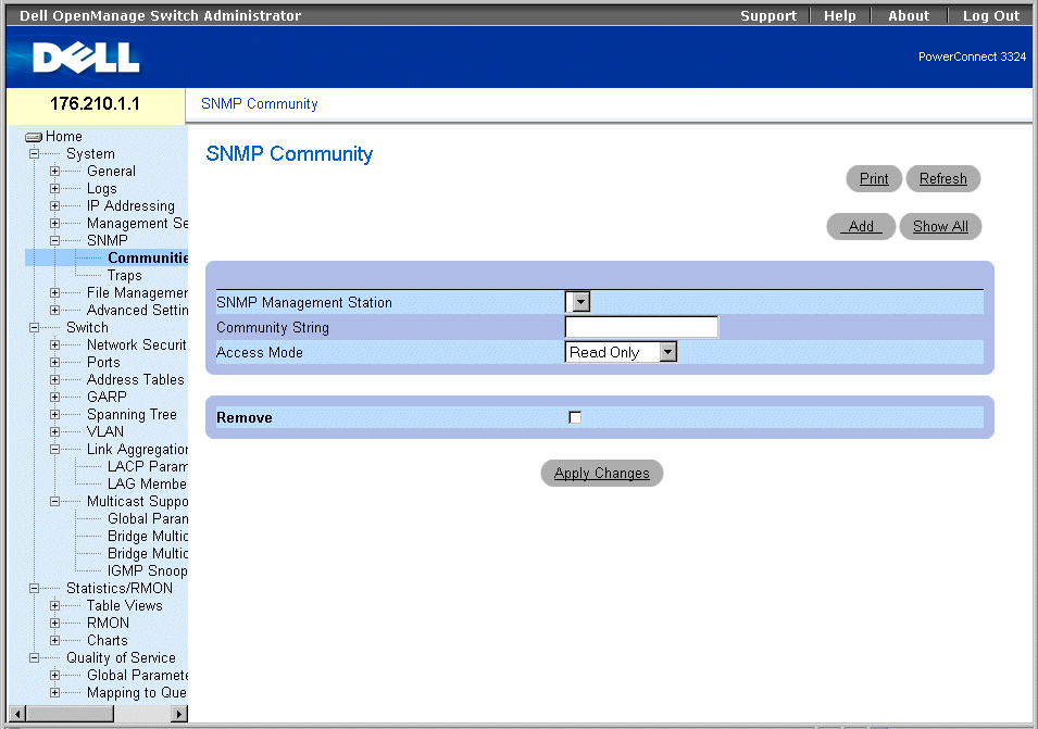
SNMP Community Page
The SNMP Community page contains the following fields:
- SNMP Management Station—Indicates a list of management station IP addresses.
- Community String—Functions as a password and used to authenticate the selected management station to the device.
- Access Mode—Defines the access rights of the community. The possible field values are:
- Read Only—Indicates that the management access is restricted to read-only, and changes cannot be made to the community.
- Read Write—Indicates that the management access is read-write and changes can be made to the device configuration, but not to the community.
- SNMP Admin—Indicates that the user has access to all device configuration options, as well to modifying the community.
- Remove—Removes a community. The possible field values are:
- Checked—Removes the community.
- Unchecked—Maintains the community.
Defining a new community:
- Open the SNMP Community page.
- Click Add. The Add SNMP Community page opens.

Add SNMP Community Page
In addition to the fields in the SNMP Community page, the Add SNMP Community page contains the following fields:
- SNMP Management—Indicates if a SNMP community is defined for a specific management station or for all management stations. The possible field values are:
- Management Station—Indicates the management station IP address. A value of 0.0.0.0 specifies all management stations.
- All—Indicates that the SNMP community is defined for all management stations.
- Define the SNMP Management, Management Station, Community String, and
Access Mode fields.
- Click Apply Changes. The new community is saved, and the device is updated.
Displaying all Communities
- Open the SNMP Community page.
- Click Show All. The Community Table page opens.

Community Table Page
Deleting Communities:
- Open the SNMP Community page.
- Click Show All. The Community Table page opens.
- Select a community from the Community Table.
- Check the Remove check box.
- Click Apply Changes. The community entry is deleted, and the device is updated.
Configuring Communities Using CLI Commands
The following table summarizes the equivalent CLI commands for viewing fields displayed in the SNMP Community page.
|
CLI Command
|
Description
|
|---|
snmp-server community string [ro | rw | su] [ip-address] | Sets up the community access string to permit access to SNMP protocol. |
show snmp | Checks the status of SNMP communications. |
The following is an example of the CLI commands:
Console (config)# snmp-server community public su 0.0.0.0
Defining Traps
From the SNMP Trap Settings page, the user can enable or disable the device to send SNMP traps or notifications. To open the SNMP Trap Settings page:
- Click System > SNMP > Traps in the Tree View. The SNMP Trap Settings page opens.
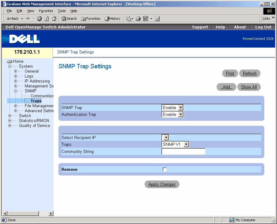
SNMP Trap Settings Page
The SNMP Trap Settings page contains the following fields:
- SNMP Trap—Enables sending SNMP traps or SNMP notifications from the switch to defined trap recipients. The possible field values are:
- Enable—Enables sending SNMP traps or SNMP notifications.
- Disable—Stops all SNMP traps from being sent.
- Authentication Trap—Enables sending SNMP traps when authentication fails to defined recipients. The possible field values are:
- Enable—Enables sending SNMP traps when authentication failed.
- Disable—Disables sending SNMP traps when authentication failed.
- Select Recipient IP—Specifies the IP address to whom the traps are sent.
- Traps —Determines the trap type sent to the selected recipient. The possible field values are:
- SNMP V1—Indicates SNMP Version 1 traps are sent.
- SNMP V2c—Indicates SNMP Version 2 traps are sent.
- Disable—Disables sending traps to the recipient.
- Community String—Identifies the community string of the trap manager.
- Remove—Removes Trap Manager Table entries.
- Checked—Removes the Trap Manager Table entry.
- Unchecked—Maintains the Trap Manager Table entry.
Enabling SNMP Traps on the device:
- Open the SNMP Trap Settings page.
- Select Enable in the SNMP Trap drop-down list.
- Define the Select Recipient IP, Traps, and Community String fields.
- Click Apply Changes. SNMP traps are enabled on the device.
Enabling Authentication Traps on the device:
- Open the SNMP Trap Settings page.
- Select Enable in the Authentication Trap drop-down list.
- Define the Select Recipient IP, Traps, and Community String fields.
- Click Apply Changes. Authentication traps are enabled on the device.
Adding a new Trap Recipient:
- Open the SNMP Trap Settings page.
- Click Add. The Add Trap Receiver/Manager page opens.

Add Trap Receiver/Manager Page
- Define the Recipient IP Address, Community String, and Trap Enable fields. (Note
that 0.0.0.0 means "All", and the traps are broadcast.)
- Click Apply Changes. the Trap Recipient/Manager is added, and the device is
updated.
Displaying the Trap Managers Table:
The Trap Managers Table contains fields for configuring trap types.
- Open the Traps page.
- Click Show All. The Traps Manager Table page opens.
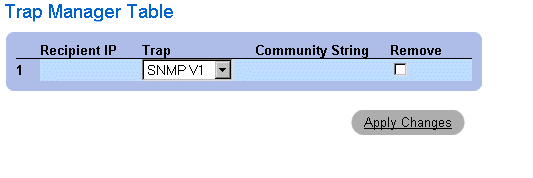
Trap Managers Table Page
Deleting a Trap Manager Table entry:
- Open the SNMP Trap Settings page.
- Click Show All. The Traps Manager Table page opens.
- Select a Trap Managers Table entry.
- Check the Remove check box.
- Click Apply Changes. The trap manager is deleted, and the device is updated.
Configuring Traps Using CLI Commands
The following table summarizes the equivalent CLI commands for viewing fields displayed in the SNMP Trap Settings page.
|
CLI Command
|
Description
|
|---|
snmp-server enable traps | Enables the switch to send SNMP traps or SNMP notifications. |
snmp-server trap authentication | Enables the switch to send SNMP traps when authentication failed. |
snmp-server host host-addr community-string [1 | 2] | Determines the trap type sent to the selected recipient. |
show snmp | Displays the SNMP communications status. |
The following is an example of the CLI commands:
Console (config)# snmp-server enable traps
Console (config)# snmp-server trap authentication
Console (config)# snmp-server host 10.1.1.1 trapRec 2
Console (config)# exit
Console# show snmp
Community-String Community-Access IP address
---------------- ---------------- -----------
public read only All
private read write 172.16.1.1
private read write 172.17.1.1
Traps are enabled.
Authentication trap is enabled.
Trap-Rec-Address Trap-Rec-Community Version
---------------- ------------------ --------
192.122.173.42 public 2
System Contact: Robert
System Location: Marketing
Managing Files
The File Management page device allows network managers to manage device software, the Image Files, and the Configuration Files. Files can be downloaded from a TFTP server.
File Management Overview
The configuration file structure consists of the following files:
- Startup Configuration File—Retains the exact device configuration when the device is powered down or rebooted. The Startup file maintains configuration commands, and configuration commands from the Running Configuration file can be saved to the Startup file.
- Running Configuration File—Contains all Startup file commands, as well as all commands entered during the current session. After the device is powered down or rebooted, all commands stored in the Running Configuration file are lost. During the startup process, all commands in the Startup file are copied to the Running Configuration file and applied to the device. During the session, all new commands entered are added to the commands existing in the Running Configuration file. Commands are not overwritten. To update the Startup file, before powering down the device, the Running Configuration file must be copied to the Startup Configuration file. The next time the device is restarted, the commands are copied back into the Running Configuration file from the Startup Configuration file.
 |
NOTE: Configuration commands are merged with the Running Configuration file and are
immediately applied to the device.
|
- Backup Configuration File—Contains a backup copy of the device configuration. The Backup file changes when the Running Configuration file or the Startup file is copied to the Backup file. The commands copied into the file replace the existing commands saved in the Backup file. The Backup file contents can be copied to either the Running Configuration or the Startup Configuration files.
- Image Files—System images are saved in two FLASH files called images (Image 1 and Image 2). The active image stores the active copy, while the other image stores a second copy. The device boots and runs from the active image. If the active image is corrupt, the system automatically boots from the non-active image. This is a safety feature for faults occurring during the software upgrade process.
To open the File Management page:
- Click System > File Management in the Tree View. The File Management page opens.
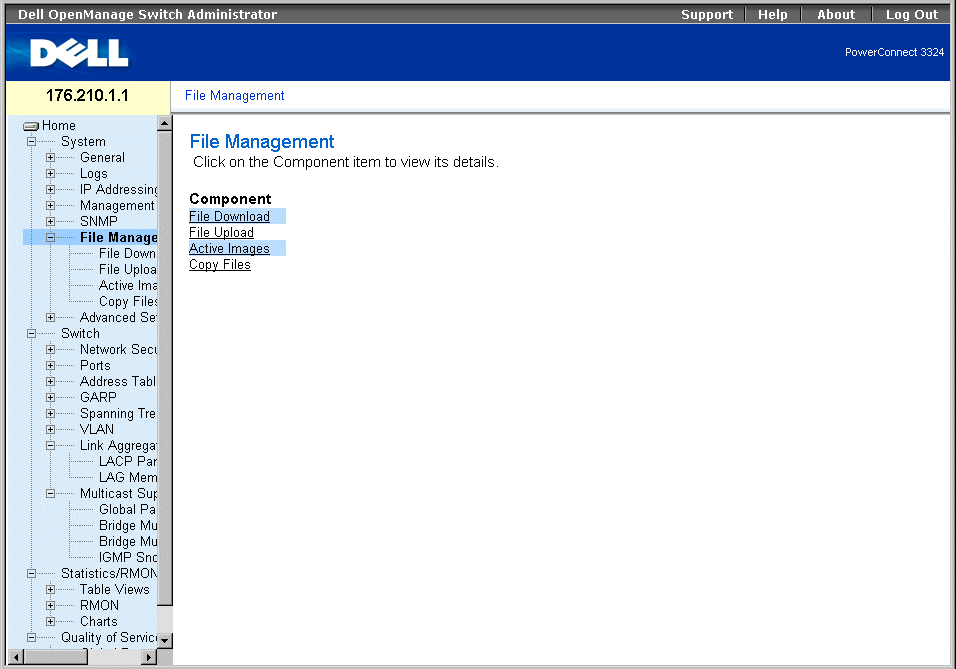
File Management Page
The File Management page contains links to:
Downloading Files
The File Download from Server page contains fields for downloading image and Configuration Files from the TFTP server to the device. To open the File Download from Server page:
- Click System > File Management > File Download in the Tree View. The File Download from Server page opens.
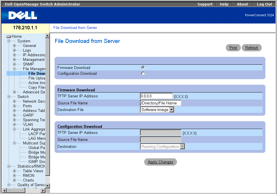
File Download From Server Page
The File Download from Server page contains the following fields:
- Firmware Download—Indicates that the Firmware file is downloaded. If Firmware Download is selected, the Configuration Download fields are grayed out.
- Configuration Download—Indicates that the Configuration file is downloaded. If Configuration Download is selected, the Firmware Download fields are grayed out.
- Firmware Download TFTP Server IP Address—Indicates the TFTP Server IP Address from which files are downloaded.
- Firmware Download Source File Name—Specifies the file to be downloaded.
- Firmware Download Destination File—Indicates the destination file type to which to the file is downloaded. The possible field values are:
- Software Image—Downloads the Image file.
- Boot Code—Downloads the Boot file.
- Configuration Download File TFTP Server IP Address—Indicates the TFTP Server IP Address through which the configuration files are downloaded.
- Configuration Download File Source File Name—Specifies the configuration files to be downloaded.
- Configuration Download File Destination—Indicates the destination file to which to the configuration files is downloaded. The possible field values are:
- Running Configuration—Downloads commands into the Running Configuration files.
- Startup Configuration—Downloads the Startup Configuration file and overwrites it.
- Backup Configuration—Downloads the Backup Configuration file and overwrites it.
Downloading files:
- Open the File Download from Server page.
- Define the file type to download.
- Define the TFTP Server IP Address, Source File Name, and Destination File fields.
- Click Apply Changes. The software is downloaded to the device.
 |
NOTE: To activate the selected Image file, reset the device. For information on resetting the
device, see "Resetting the Device".
|
Downloading Files Using CLI Commands
The following table summarizes the equivalent CLI commands for viewing fields displayed in the File Download from Server page.
|
CLI Command
|
Description
|
|---|
copy source-url destination-url [snmp] | Copies any file from a source to a destination. |
The following is an example of the CLI commands:
console# copy running-config tftp://11.1.1.2/pp.txt
 |
NOTE: Each ! indicates that ten packets were successfully transferred.
|
Accessing file 'file1' on 172.16.101.101.
Loading file1 from 172.16.101.101:
!!!!!!!!!!!!!!!!!!!!!!!!!!!!!!!!!!!!!!!!!!!!!!!!!!!!!!!!!!!!!
!!!!!!!!!!!!!!!!!!!!!!!!!!!!!!!!!!!!!!!!!!!!!!!!!!!!!!!!!!!!!!!!!!
!!!!!!!!!!!!!!!!!!!!!!!!!!!!!!!!!!!!!!!!!!!!!!!!!!!!!!!!!!!!!!!!!!
!!!!!!!!!!!!!!!!!!!!! [OK]
Copy took 0:01:11 [hh:mm:ss]
Uploading Files
The File Upload to Server page contains fields for uploading the software from the TFTP server to the device. The Image file can also be uploaded from the File Upload to Server page. To open the File Upload to Server page:
- Click System > File Management > File Upload in the Tree View. The File Upload to Server page opens:
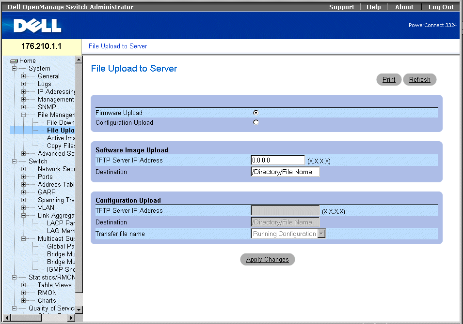
File Upload to Server Page
The File Upload to Server page contains the following fields:
- Firmware Upload—Indicates that the Firmware file is uploaded. If Firmware Upload is selected, the Configuration Upload fields are grayed out.
- Configuration Upload—Indicates that the Configuration file is uploaded. If Configuration Upload is selected, the Software Image Upload fields are grayed out.
- Software Image Upload TFTP Server IP Address—Indicates the TFTP Server IP Address to which the Software Image is uploaded.
- Software Image Upload Destination—Specifies the Software Image file path to which the file is uploaded.
- Configuration Upload TFTP Server IP Address—Indicates the TFTP Server IP Address to which the Configuration file is uploaded.
- Configuration Upload Destination—Specifies the Configuration file path from which the file is uploaded.
- Configuration Upload Transfer file name—Indicates the software file to which the configuration is uploaded. The possible field values are:
- Running Configuration—Uploads the Running Configuration file.
- Startup Configuration—Uploads the Startup Configuration file.
- Backup Configuration—Uploads the Backup file.
Uploading files:
- Open the File Upload to Server page.
- Define the file type to upload.
- Define the TFTP Server IP Address, Destination, and Transfer file name fields.
- Click Apply Changes. The software is uploaded to the device.
Uploading Files Using CLI Commands
The following table summarizes the equivalent CLI commands for viewing fields displayed in the File Upload to Server page.
|
CLI Command
|
Description
|
|---|
copy source-url destination-url [snmp] | Copies any file from a source to a destination. |
The following is an example of the CLI commands:
-----------------------------------------------------
console# copy tftp://16.1.1.200/file1 image
!!!!!!!!!!!!!!!!!!!!!!!!!!!!!!!!!!!!!!!!!!!!!!!!!!!!!!!!!!!!!!!!!!
!!!!!!!!!!!!!!!!!!!!!!!!!!!!!!!!!!!!!!!!!!!!!!!!!!!!!!!!!!!!!!!!!!
!!!!!!!!!!!!!!!!!!!!!!!!!!!!!!!!!!!!!!!!!!!!!!!!!!!!!!!!!!!!!!!!!!
!!!!!!!!!!!!!!!!!!!!!!!!!!!!!!!!!!!!!!!!!!!!!!!!!!!!!!!!!!!!!!!!!!
!!!!!!!!!!!!!!!!!!!!!!!!!!!!!!!!!!!!!!!!!!!!!!!!!!!!!!!!!!!!!!!!!!
!!!!!!!!!!!!!!!!!!!!!!!!!!!!!!!!!!!!!!!!!!!!!!!!!2883576 bytes
copied in 00:00:10 [hh:mm:ss]
Resetting the Active Image
The Active Images page allows network managers to select and reset the Image files. The Active Image file for each unit in a stacking configuration can be individually selected. To open the Active Images page:
- Click System > File Management > Active Images in the Tree View. The Active Images page opens.
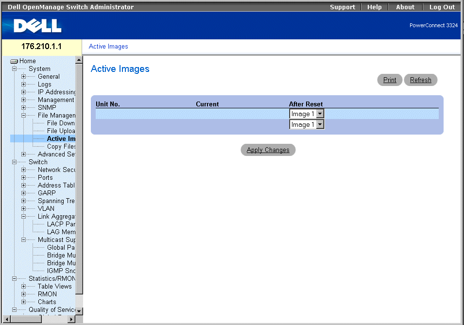
Active Images Page
The Active Images page contains the following fields:
- Unit No.—Displays the unit number for which the Image file is selected.
- Current—Displays the Image file which is currently active on the unit.
- After Reset—Indicates the Image file which is active on the unit after the device is reset.
Selecting an Image File:
- Open the Active Images page.
- Select an Image file for a specific unit in the After Reset field.
- Click Apply Changes. The Image file is selected. The Image file reloads only after the
next reset. The currently selected Image file continue to run until the next device
reset. For instruction on resetting the device, see "Resetting the Device".
Working with the Active Image File Using CLI Commands
The following table summarizes the equivalent CLI commands for viewing fields displayed in the Active Images page.
|
CLI Command
|
Description
|
|---|
boot system [unit | unit ] {image-1 | image-2}
| Specifies the system image that the device loads at startup.
|
The following is an example of the CLI commands:
Console# boot system image-1
Copying and Deleting Files
Files can be copied and deleted from the Copy Files page. To open the Copy Files page:
- Click System > File Management > Copy Files in the Tree View. The Copy Files page opens.
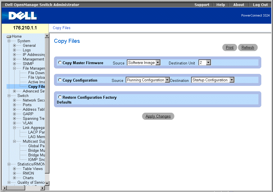
Copy Files Page
The Copy Files page contains the following fields:
- Copy Master Firmware—Copies either the Software Image and/or Boot Code from the master unit to a selected stacking unit.
- Source—Copies either the Software Image or Boot Code files to the selected stacking unit.
- Destination Unit—Indicates the stacking unit to which the Software Image or Boot Code is copied.
- Copy Configuration—Copies either the Running Configuration, Startup Configuration or Backup Configuration files to the Startup Configuration or Backup Configuration files.
- Source—Indicates either the Running Configuration, Startup Configuration, or Backup Configuration files to copy to the selected stacking unit.
- Destination—Indicates the configuration to overwrite, either the startup configuration or backup configuration.
- Restore Configuration Factory Defaults—Restores the Factory Configuration default files by erasing the Startup-Config File. Note that the Backup-Config File is not erased. The possible field values are:
- Checked—Restores the factory defaults.
- Unchecked—Maintains the current configuration settings.
Copying Files:
- Open the Copy Files page.
- Select either the Copy Configuration or Copy Master Firmware field.
- Define the Source and Destination fields for the file.
- Click Apply Changes. The file is copied, and the device is updated.
Restoring Company Factory Default Settings:
- Open the Copy Files page.
- Select the Restore Company Factory Defaults fields.
- Click Apply Changes. The company factory default settings are restored, and the
device is updated.
Copying and Deleting Files Using CLI Commands
The following table summarizes the equivalent CLI commands for viewing fields displayed in the Copy Files page.
|
CLI Command
|
Description
|
|---|
delete startup-config | Deletes the startup-config file. |
copy source-url destination-url [snmp] | Copies any file from a source to a destination |
The following is an example of the CLI commands:
Console# delete startup-config
This command will reset the whole system and disconnect your Telnet
session. Do you want to continue (y/n) [n]?
Console # copy tftp://172.16.101.101/file1 image
Accessing file 'file1' on 172.16.101.101.
Loading file1 from 172.16.101.101:
!!!!!!!!!!!!!!!!!!!!!!!!!!!!!!!!!!!!!!!!!!!!!!!!!!!!!!!!!!!!!!!!!!
!!!!!!!!!!!!!!!!!!!!!!!!!!!!!!!!!!!!!!!!!!!!!!!!!!!!!!!!!!!!!!!!!!
!!!!!!!!!!!!!!!!!!!!!!!!!!!!!!!!!!!!!!!!!!!!!!!!!!!!!!!!!!!!!!!!!!
!!!!!!!!! [OK]
Copy took 0:01:11 [hh:mm:ss]
Defining Advanced Settings
Device Tuning is used to determine the maximum amount of entries allowed in the various tables listed. Changes are implemented only after the device is reset. To open the Tuning page:
- Click System > Advanced Settings in the Tree View. The Tuning page opens.
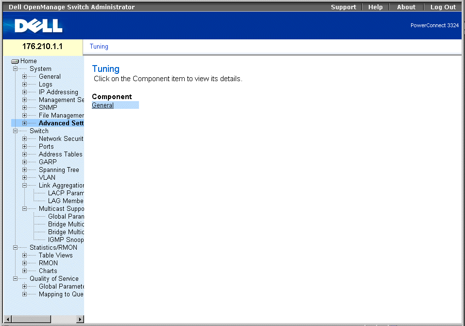
Tuning Page
The Tuning page contains the following link:
Configuring General Device Tuning Parameters
The General Settings page allows network managers to define general device parameters. To open the General Settings page:
- Click System > Advanced Settings > General in the Tree View. The General Settings page opens.
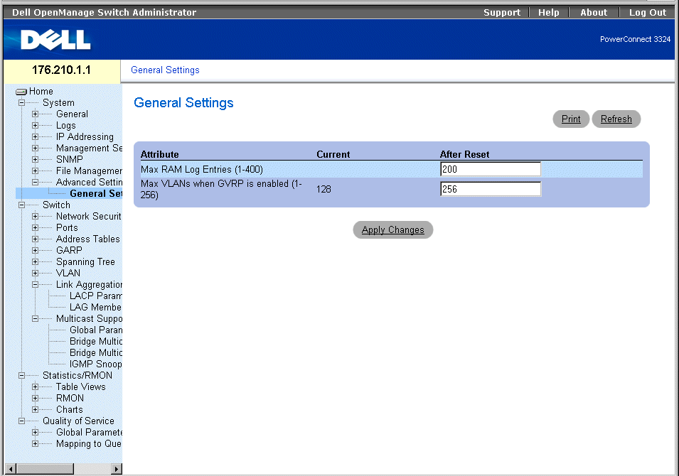
General Settings Page
The General Settings page contains the following columns:
- Attribute—The general setting attribute.
- Current—The current value.
- After Reset—The future (after reset) value. By entering a value in the After Reset column, memory is allocated to the field table.
The General Tuning page contains the following fields:
- Max RAM Log Entries (1-400)—Indicates the maximum number of RAM Log entries. When the Log entries are full, the log is cleared and the Log file is restarted.
- Max VLANs when GVRP is enabled (1-256)—Defines the overall number of VLANs when GVRP is enabled.
 |
NOTE: The maximum number of GVRP VLANs includes all the VLANs participating in GVRP
operation, whether they are static or dynamic VLANs.
|
Viewing RAM Log Entries Counter Using the CLI Commands
The following table summarizes the equivalent CLI commands for viewing fields displayed in the General Settings page.
|
CLI Command
|
Description
|
|---|
logging buffered size number | Sets the number of syslog messages stored in the internal buffer (RAM). |
gvrp max vlan | Configures the maximum number of VLANs when GVRP is enabled. |
The following is an example of the CLI commands:
Console (config)# logging buffered size 300
Back to Contents Page
 Defining General Device Information
 Defining General Device Information


