 Installation Precautions
Dell™ PowerConnect™ 3324/3348 User's Guide
 Cable, Port, and Pinout Information

|
CAUTION: The rack or cabinet housing the switch should be adequately secured to prevent it from becoming unstable and/or falling over. |

|
CAUTION: Ensure the power source circuits are properly grounded. |

|
CAUTION: Observe and follow service markings. Do not service any product except as explained in your system documentation. Opening or removing covers marked with a triangular symbol with a lighting bolt may cause electrical shock. These components are to be serviced by trained service technicians only. |

|
CAUTION: Ensure the power cable, extension cable, and/or plug is not damaged. |

|
CAUTION: Ensure the product is not exposed to water. |

|
CAUTION: Do not push foreign objects into the device, as it may cause a fire or electric shock. |

|
CAUTION: Allow the product to cool before removing covers or touching internal equipment. |

|
CAUTION: Ensure the switch does not overload the power circuits, wiring, and over-current protection. To determine the possibility of overloading the supply circuits, add together the ampere ratings of all switches installed on the same circuit as the switch. Compare this total with the rating limit for the circuit. The maximum ampere ratings are usually printed on the switch, near their AC power connectors. |
 |
NOTICE: Ensure the device is not exposed to radiators and/or heat sources. |
 |
NOTICE: Ensure the cooling vents are not blocked. |
 |
NOTICE: Use the device only with approved equipment. |
 |
NOTICE: Do not install the switch in an environment where the operating ambient temperature might exceed 40ºC (122ºF). |
 |
NOTICE: Ensure the air flow around the front, sides, and back of the switch is not restricted. |
Dell™ PowerConnect™ 3324/3348 series equipment can be mounted in a standard 19-inch equipment rack or placed on a table. Before installing the unit, verify that the location chosen for installation meets the site requirements described below.
While unpacking PowerConnect 3324/3348, ensure that the following items are included:
 |
NOTE: Before unpacking the PowerConnect 3324/3348 switch, inspect the package and report any evidence of damage immediately. |

|
CAUTION: Disconnect all cables from the unit before mounting the PowerConnect 3324/3348 switch in a rack or cabinet. |
Installing PowerConnect 3324/3348:
The PowerConnect 3324/3348 must be installed on a flat surface if it is not installed on a rack. The surface must be able to support the weight of the device and the device cables.
PowerConnect 3324/3348 supports stacking up to six PowerConnect 3324/3348 devices or up to 192 Fast Ethernet ports and six Giga ports. Each PowerConnect 3324/3348 stack contains a single Master unit, while the remaining units are considered stacking members. All management is done through the Master unit. Both 24-port and 48-port devices can be included in the stack.
To enable stacking, units must be stacked with a Stack Module connected to port G2 in the SFP slot.
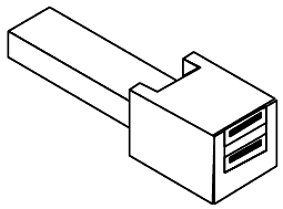
 |
NOTE: If the Stacking ring is not completed, the stack does not function. |
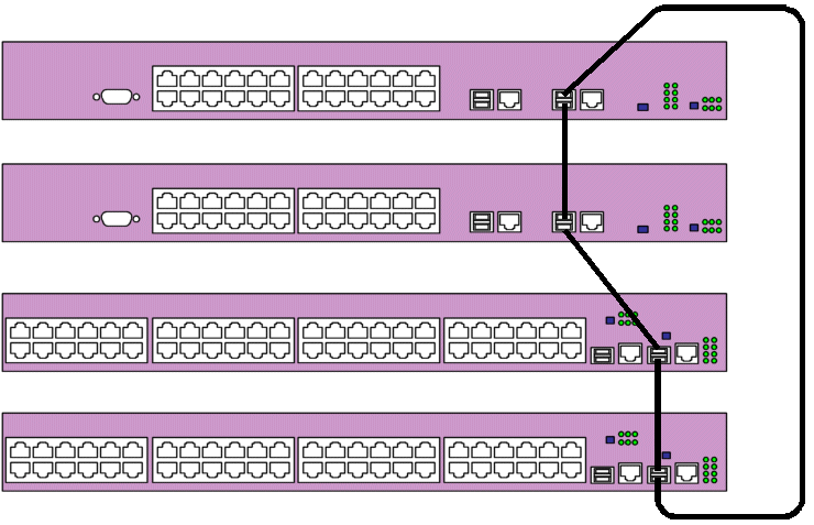
For more information on configuring stacks, see "Configuring Stacking".
The following section contains instruction for connecting the PowerConnect 3324/3348 to a AC power connection. The PowerConnect 3324/3348 is supplied with power from:
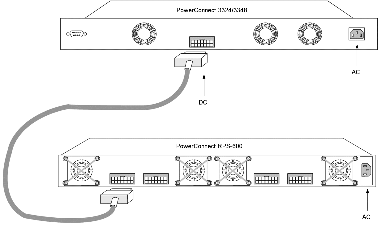
Connecting PowerConnect 3324/3348 to a Power Supply
AC power should be supplied to the unit through a 1.5m (5 foot) standard power cable with safety-ground connected.
To connect power to PowerConnect 3324/3348:
This section describes the PowerConnect 3324/3348 physical interfaces and provides information about cable connections. Stations are connected to PowerConnect 3324/3348 ports through the physical interface ports on the front panel. For each station, the appropriate mode (Half/Full Duplex, Auto) is set.
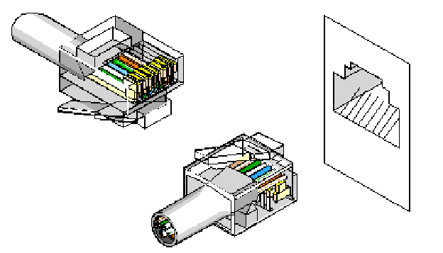
The ports are all standard RJ45 Ethernet ports. Switching ports can connect to stations wired in standard RJ45 Ethernet station mode using straight cables. Transmission devices use crossed cables to connect to each other.
The following figure illustrates the RJ45 pin number allocations for the 10/100M ports.
|
Pin |
Use |
|---|---|
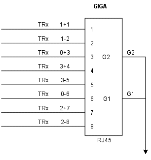
The following figure illustrates the Gigaport Connector:
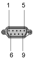
A serial cable connects PowerConnect 3324/3348 to a terminal for the initial setup and configuration. (A PC running terminal emulation software can also be used.) The serial cable is a female-to-female DB-9 crossover cable.
The following figure illustrates the DB-9 connector.
|
Pin |
Use |
|---|---|
This section describes how to connect the various cables to the PowerConnect 3324/3348 device.
The serial port connector is a DB-9 type connector. A supplied interface cable is required to connect the device.
To connect the device:

PowerConnect 3324 Terminal Connection
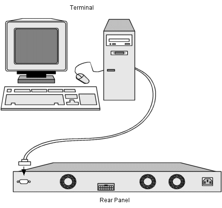
PowerConnect 3348 Terminal Connection