 PowerConnect 3324/3348 Description
Dell™ PowerConnect™ 3324/3348 User's Guide
 PowerConnect 3324/3348 Description
This device has the following dimensions:
The rear panel of the Dell™ PowerConnect™ 3324/3348 is shown in the following figure:


This section describes different PowerConnect 3324/3348 hardware components, and includes the following topics:
The PowerConnect 3324/3348 includes the following hardware components:
The Mode Button toggles between port activity and port duplex settings.
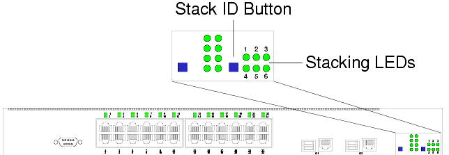
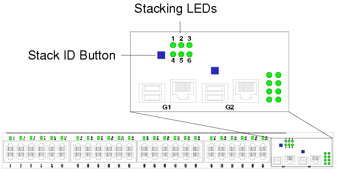
The PowerConnect 3324/3348 front panel contains a Stack ID button that permits network administrators to manually select the Stack Master and stack members.
 |
NOTE: The Stack Master and stack members must be selected within 15 seconds after booting the device. If the Stack Master is not selected within 15 seconds, the device must be reset to select the Unit IDs. |
Once the Stack Master is selected, the remaining devices are defined as stack members. Master units receive the Unit ID of 1. Stack members receive a separate Unit ID (2-6). For example, if there are 4 units in a stack, the Master unit is 1, the second stack member is 2, the third stack member is 3, and the fourth stack member is 4.
PowerConnect 3324/3348 Stacking modules are connected to port G2. The Stack module is a mini GBIC module with two stacking connectors: RX and TX. RX is the lower connection point, and TX is the upper connection point. The module is connected to other stacking units using a stacking cable connection. The top unit's RX is connected to the lower unit's TX. This completes the Ring Topology. The Stacking Connections figure illustrates the Ring Topology.
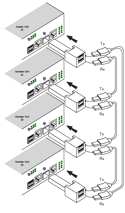
For more information about connecting Stacking cables, see "Connecting Stacking Cables".
The PowerConnect 3324 features 24 FE 10BaseT/100BaseTX UTP copper RJ45 ports per unit and 2 combo ports. The PowerConnect 3348 features 48 FE 10BaseT/100BaseTX UTP copper RJ45 ports per unit and 2 combo ports. Each combo port is a single logical port that has the following two physical interfaces:
Only one of the two physical connections of a combo port may be used at any one time.
If auto-MDIX is enabled, PowerConnect 3324/3348 automatically detects and corrects the difference between crossover and straight-through cables on all ports.
PowerConnect 3324/3348 supports half and full duplex mode 10/100 M bps speed for copper ports.
The console port interface supports synchronous data of eight data bits, one stop bit, and no parity. All RS232 pins are supported (9 pins) for Modem support.
The front panel LEDs in the following figures indicate the status of port links and modes, power supply status, stacking status, and system diagnostics. The LED types are as follows:
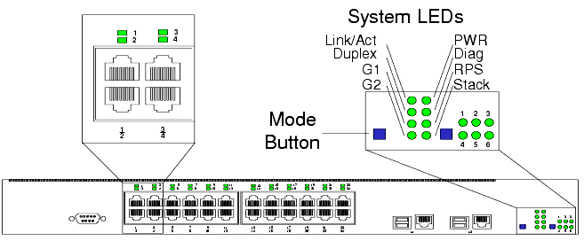
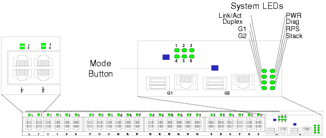
Each port has one corresponding LED located above the port. The LEDs show either link activity or duplex mode, depending on the port LED display mode. For information about setting the LED display mode, see "System LEDs".
|
Color |
Activity |
Definition |
|---|---|---|
|
Color |
Activity |
Definition |
|---|---|---|
The eight system LEDs indicate the status of various aspects of the device:
|
Color |
Activity |
Definition |
|---|---|---|
Giga Port Link Activity Status
When a power supply fails, an error message and several traps are generated. The status of each power supply is indicated by LEDs on the front panel.
|
LED |
Color |
Activity |
Definition |
|---|---|---|---|
Power, Diagnostic, and Stack LEDs
The stacking LEDs indicate the unit's position in the stack. As shown in the front panel illustrations at the start of this section, the stacking LEDs are numbered 1 through 6. Each unit in the stack has one stacking LED lit, indicating its position in the stack. When stacking LED 1 is lit, the unit is the master unit. When one of the stacking LEDs numbered 2 through 6 is lit, the unit is the corresponding stacking member unit.