Back to Contents Page
Dell™ PowerEdge™ SC1420 Systems Service Only Parts Replacement Procedures
 Before You Begin
Recommended Tools
Bezel
Control Panel
I/O Panel
Chassis Intrusion Switch
Memory Cooling Fan and Shroud
Power Supply
System Board
Before You Begin

|
CAUTION: See your System Information Guide for complete information about safety precautions, working inside the computer, and protecting against electrostatic discharge. |
The procedures in this document require that you open the system and work inside the system. While working inside the system, do not attempt to service the system except as explained in this document and in the Installation and Troubleshooting Guide and the User's Guide available on support.dell.com. Always follow the instructions closely, and ensure that you review all safety precautions in the Product Information Guide.
The Installation and Troubleshooting Guide contains information on system indicators, messages, and codes; system diagnostics; troubleshooting; parts removal and replacement procedures; and jumpers, switches, and connectors.
The User's Guide contains information on the System Setup program.
Recommended Tools
You may need the following items to perform the procedures in this section:
- Key to the system keylock
- #2 Phillips screwdriver
- Wrist grounding strap
Bezel
Removing the Bezel
|
|
CAUTION: See your System Information Guide for complete information about safety precautions, working inside the computer, and protecting against electrostatic discharge. |
- Turn off the system and attached peripherals, and disconnect the system from the electrical
outlet.
- Open the system.
- Remove all the drives (hard drives, optical drives, and diskette drive).
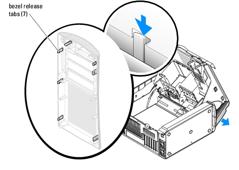
- Release the bezel by pressing the seven bezel release tabs. See Figure 1-1.
- After pressing the seven bezel release tabs, close the system half way and pull the bezel away
from the system.
Figure 1-1. Removing the Bezel
Installing the Bezel
- Align the seven bezel release tabs with the system.
- Press the bezel onto the system until it snaps into place.
- Install all the drives that you removed.
- Close the system.
- Reconnect the system to the electrical outlet, and turn on the system.
Control Panel
You must remove the bezel to access the control panel.
Removing the Control Panel
|
|
CAUTION: See your System Information Guide for complete information about safety precautions, working inside the computer, and protecting against electrostatic discharge. |
- Turn off the system and attached peripherals, and disconnect the system from the electrical
outlet.
- Open the system.
- Remove the bezel. See "Removing the Bezel."
- Disconnect the control panel cable from the I/O panel. See Figure 1-3.
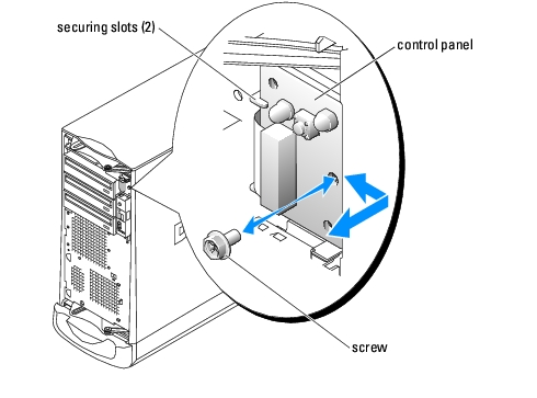
- Using a #2 Phillips screwdriver, remove the screw that secures the control panel to the front
panel. See Figure 1-2.
Figure 1-2. Removing and Installing the Control Panel
- Carefully pull the control panel cable through the front panel while removing the control
panel.
Installing the Control Panel
- Carefully slide the control panel cable through the front panel.
- Slide the control panel into the two slots in the securing bracket on the front panel. See
Figure 1-2.
- Align the control panel mounting hole with the hole in the front panel.
- Using a #2 Phillips screwdriver, install the screw that secures the control panel to the front
panel.
- Connect the control panel cable to the I/O panel. See Figure 1-3.
- Install the bezel. See "Installing the Bezel."
- Close the system.
- Reconnect the system to the electrical outlet, and turn on the system.
I/O Panel
Removing the I/O Panel
|
|
CAUTION: See your System Information Guide for complete information about safety precautions, working inside the computer, and protecting against electrostatic discharge. |
- Turn off the system and attached peripherals, and disconnect the system from the electrical
outlet.
- Open the system.
- Disconnect the following cables from the I/O panel:
- Control panel
- Chassis intrusion switch
- I/O panel
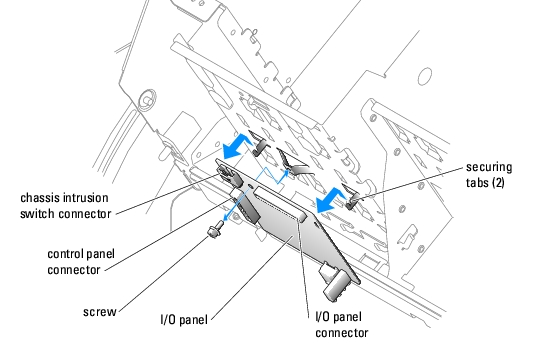
- Using a #2 Phillips screwdriver, remove the screw that secures the I/O panel to the chassis.
See Figure 1-3.
Figure 1-3. Removing and Installing the I/O Panel
- Slide the I/O panel backward and remove the I/O panel from the system.
Installing the I/O Panel
- Align the I/O panel with the two securing tabs on the chassis. See Figure 1-3.
- Slide the I/O panel forward until it stops.
- Using a #2 Phillips screwdriver, install the screw that secures the I/O panel to the chassis.
- Connect the following cables:
- I/O panel
- Chassis intrusion switch
- Control panel
- Close the system.
- Reconnect the system to the electrical outlet, and turn on the system.
Chassis Intrusion Switch
Removing the Chassis Intrusion Switch
|
|
CAUTION: See your System Information Guide for complete information about safety precautions, working inside the computer, and protecting against electrostatic discharge. |
- Turn off the system and attached peripherals, and disconnect the system from the electrical
outlet.
- Open the system.
- Disconnect the chassis intrusion switch cable from the switch connector on the I/O panel. See
Figure 1-3.
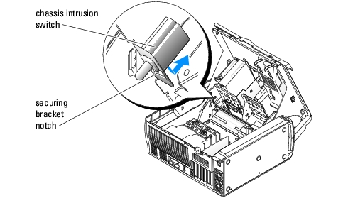
- Slide the chassis intrusion switch out of the securing bracket notch. See Figure 1-4.
Figure 1-4. Removing and Installing the Chassis Intrusion Switch
- Remove the switch and its attached cable from the system.
Installing the Chassis Intrusion Switch
- Align the chassis intrusion switch with the securing bracket notch. See Figure 1-4.
- Slide the switch into the securing bracket notch.
- Connect the switch cable to the switch connector on the I/O panel. See Figure 1-3.
- Close the system.
- Reconnect the system to the electrical outlet, and turn on the system.
Memory Cooling Fan and Shroud

|
NOTICE: If you install more than 4 GB of memory, you must install the memory cooling fan and shroud to prevent the memory from over heating. If you do not install the memory cooling fan and shroud, you will receive an error message stating that you must install a fan or remove some memory. |
Installing the Memory Cooling Fan and Shroud
|
|
CAUTION: See your System Information Guide for complete information about safety precautions, working inside the computer, and protecting against electrostatic discharge. |
- Turn off the system and attached peripherals, and disconnect the system from the electrical
outlet.
- Open the system.
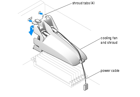
- Align the memory cooling fan and shroud tabs with the holes on the back panel. See
Figure 1-5.
Figure 1-5. Installing the Memory Cooling Fan and Shroud
- Insert the tabs and lower the memory cooling fan and shroud until it snaps into place.
- Connect the memory cooling fan and shroud power cable to the system board. See Figure 1-5.
- Close the system.
- Reconnect the system to the electrical outlet, and turn on the system.
Power Supply
Removing the Power Supply
|
|
CAUTION: See your System Information Guide for complete information about safety precautions, working inside the computer, and protecting against electrostatic discharge. |
- Turn off the system and attached peripherals, and disconnect the system from the electrical
outlet.
- Open the system.
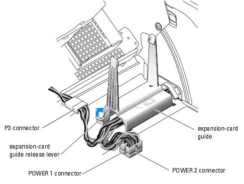
- Remove the expansion-card guide:
- Pull up on the expansion-card guide release lever. See Figure 1-6.
- Slide the guide toward the power supply.
- Lift the guide out of the system.
- Disconnect the following power supply cables:
- P3 connector for the hard drives. See Figure 1-6.
- POWER 1 connector on the system board.
- POWER 2 connector on the system board.
Figure 1-6. Removing the Expansion-Card Guide
- While pressing the power-supply release button, slide the power supply toward the back of the
system. See Figure 1-7.
Figure 1-7. Removing and Installing the Power Supply
- While pulling the power supply away from the system, carefully guide the power-supply
cables through the hole in the side of the chassis.
Installing the Power Supply
- Carefully guide the power-supply cables through the hole in the side of the chassis.
- Align the tabs on the power supply with the securing notches in the chassis. See Figure 1-7.
- Slide the power supply toward the front of the system until it snaps into place.
- Install the expansion-card guide (see Figure 1-6):
- Align the four expansion-card guide tabs with the securing slots in the chassis.
- Lower the guide into the securing slots and slide the guide away from the power supply
until it snaps into place.
- Connect the following power supply cables (see Figure 1-6):
- POWER 2 connector on the system board.
- POWER 1 connector on the system board.
- P3 connector for the hard drives. See Figure 1-6.
- Close the system.
- Reconnect the system to the electrical outlet, and turn on the system.
System Board
|
|
CAUTION: See your System Information Guide for complete information about safety precautions, working inside the computer, and protecting against electrostatic discharge. |
|
|
CAUTION: The heat sink can get hot during operation. To avoid burns, ensure that the system has sufficient time to cool before removing the system board. |
The system board and system board tray are removed and replaced as a single assembly.
Removing the System Board
- Turn off the system and attached peripherals, and disconnect the system from the electrical
outlet.
- Open the system.
- Disconnect the following cables from the system board (see Figure A-3 in the Installation and
Troubleshooting Guide):
- Power-supply cable from the POWER 1 connector
- Power-supply cable from the POWER 2 connector
- If applicable, diskette data cable from the DISKETTE connector
- I/O panel cable from the PANEL connector
- 5.25-inch device data cable from IDE 1 connector
- Expansion-card fan from the FAN_CCAG connector
- If applicable, optical-drive data cable from IDE 2 connector
- If applicable, SATA hard-drive data cable(s) from SATA0 and SATA1 connector(s)
- If applicable, remove the memory cooling shroud. See "Installing the Memory Cooling Fan
and Shroud."
- Remove all expansion cards and any attached cables.
- Remove all memory modules.

|
NOTE: Record the memory-module socket locations to ensure proper reinstallation of the memory modules. |
- Remove the processor cooling shrouds.
- If applicable, remove the VRM.
- Remove the retention clips that secure the heat sink to the retention module.
|
|
NOTICE: The processor and heat sink can become extremely hot. Allow sufficient time for the processor and heat sink to cool before handling. |
|
|
NOTICE: To prevent damaging the processor, do not pry the processor off the heat sink. |
- Rotate the heat sink slightly to separate the heat sink from the processor, and then gently lift
the heat sink off the processor.
|
|
NOTE: Remove the heat sink while the processor is still warm. |
|
|
NOTICE: Be careful not to bend any of the pins when removing the processor. Bending the pins can permanently damage the processor. |
- Remove the processor.
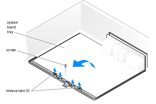
- Using a #2 Phillips screwdriver, remove the screw that secures the system board tray to the
chassis. See Figure 1-8.
Figure 1-8. Removing and Installing the System Board
- While pulling up on the two system board tray release tabs, slide the tray toward the front of
the system and then remove the system board tray from the system.
- Place the system board tray on a flat nonconductive surface.
Installing the System Board
- While lowering the system board into the chassis, align the I/O connectors with the opening
in the back panel.
- Slide the system board backward until the system board snaps into place.
- Using a #2 Phillips screwdriver, install the screw that secures the system board tray to the
chassis. See Figure 1-8.
- Install the processor(s).
- Before installing the heat sink(s), clean the heat sink(s) to remove any thermal grease.
- Apply the thermal grease to the processor(s).
- Install the heat sink(s).
- Install the retention clips that secure the heat sink to the retention module.
- If applicable, install the VRM.
- Install the processor cooling shrouds.
- Install the memory modules in the same sockets that they were removed from.
- If your system contains more than 4 GB of memory, install the memory cooling fan and
shroud. See "Installing the Memory Cooling Fan and Shroud."
- Install the expansion cards and connect any cables.
- Connect the following cables to the system board (see Figure A-3 in the Installation and
Troubleshooting Guide):
- Power-supply cable from the POWER 1 connector
- Power-supply cable from the POWER 2 connector
- If applicable, diskette data cable from the DISKETTE connector
- I/O panel cable from the PANEL connector
- 5.25-inch device data cable from IDE 1 connector
- Expansion-card fan from the FAN_CCAG connector
- If applicable, optical-drive data cable from IDE 2 connector
- If applicable, SATA hard-drive data cable(s) from SATA0 and SATA1 connector(s)
- Close the system.
- Reconnect the system to the electrical outlet, and turn on the system.
Back to Contents Page