Back to Contents Page
Dell™ PowerEdge™ 1600SC Systems
Service Manual
The procedures in this guide require that you remove the cover and work inside the system. While working inside the system, do not attempt to service the system except as explained in this manual and elsewhere in the system documentation. Always follow the instructions closely and review all of the procedures in "Safety Instructions" in the System Information Guide.

|
CAUTION: Only trained service technicians are authorized to remove the system cover and access any of the components inside the system. See the System Information Guide for complete information about safety precautions, working inside the computer, and protecting against electrostatic discharge. |
This section provides servicing procedures for components inside the system. Before you start any of the procedures in this section, perform the following tasks:
|
|
Read the safety information in the System Information Guide. |
When there is no replacement procedure provided, use the removal procedure in reverse order to install the replacement part.
- Key to the system keylock
- 1/4-inch nut driver
- #1 and #2 Phillips screwdriver
- Small needle nose pliers
- Wrist grounding strap
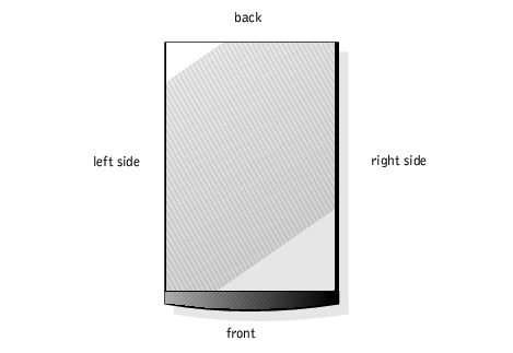
The illustrations in this document are based on the positioning of the system as shown in Figure 4-1.
Figure 4-1. System Orientation
The front bezel has status and attention indicators. You must remove the bezel to remove the cover.
|
|
CAUTION: Only trained service technicians are authorized to remove the system cover and access any of the components inside the system. See the System Information Guide for complete information about safety precautions, working inside the computer, and protecting against electrostatic discharge. |
 |
NOTICE: To remove the bezel, the system must be standing upright.
|
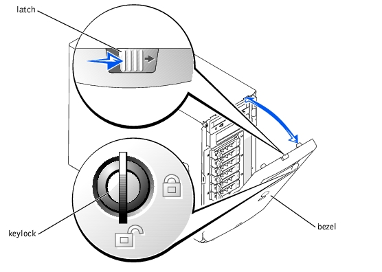
- Using the system key, unlock the front bezel (see Figure 4-2).
Figure 4-2. .Removing the Bezel
|
NOTICE: Figure 4-2 shows the system standing upright as the bezel is being removed.
However, before you service components inside the system, lay the system on its right side.
|
- Slide the latch to the right and pull the upper edge of the bezel away from the front
panel (see Figure 4-2).
- Pivot the bezel downward until it is at right angles to the front panel.
- Unsnap the bezel from the metal clips on the front panel.
- Before working on the system, lay the system on its right side.
- Snap the two tabs on the lower inside edge of the bezel into the corresponding clips on
the system front panel, and pivot the bezel upward to its closed position.
- Using the system key, lock the bezel.
To upgrade or troubleshoot the system, remove the cover to gain access to internal components.
|
|
CAUTION: Only trained service technicians are authorized to remove the system cover and access any of the components inside the system. See the System Information Guide for complete information about safety precautions, working inside the computer, and protecting against electrostatic discharge. |
- Remove the bezel (see "Removing the Bezel").
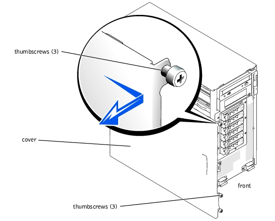
- Loosen the three thumbscrews on the left-side cover (see Figure 4-3).
- Grasp the cover at both ends and slide it toward the front of the system.
- Lift the cover away from the system.
Figure 4-3. Removing the Cover
|
NOTICE: Figure 4-3 shows the system standing upright as the cover is being removed.
However, before you service components inside the system, lay the system on its right side.
|
- Ensure that no tools or loose parts are left inside the system.
- Fit the cover on the side of the system, and slide the cover backward.
- Tighten the three thumbscrews on the cover (see Figure 4-3).
- Install the bezel (see "Installing the Bezel").
Figure 4-4 shows an interior view of the system.
Figure 4-4. Inside the System
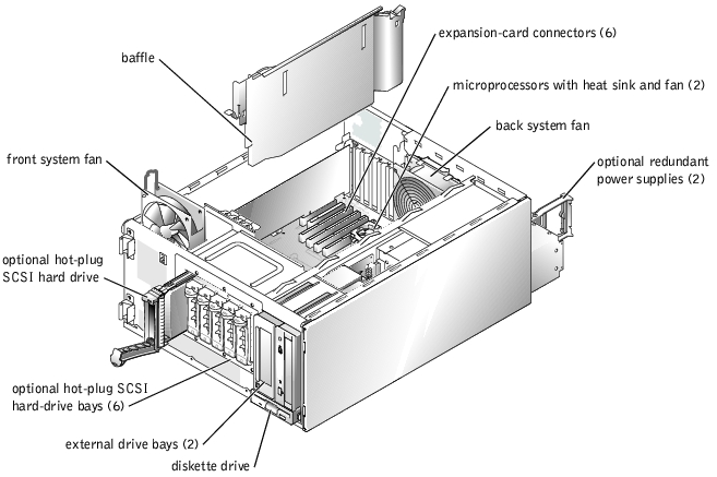
The system board contains the system's control circuitry and other electronic components. Several hardware options, such as the microprocessors and memory, are installed directly on the system board.
The system accommodates up to six expansion cards (two 64-bit, 100-MHz PCI-X cards, two 64-bit, 66-MHz PCI cards, and two 32-bit, 33-MHz PCI cards). System memory is contained in four memory module sockets.
The system supports a 3.5-inch diskette drive and up to two externally accessible 5.25-inch drives, such as CD, DVD, or tape drives. The hard-drive bays support up to four IDE hard drives or four non-hot-plug SCSI hard drives or up to six hot-plug SCSI hard drives. The hard drives connect to a controller on the system board or to a controller card.
The vertical plastic baffle in the center of the system improves system cooling by guiding the airflow within the system. You must remove the baffle when performing certain procedures inside the system to improve access to some internal components.
Figure 4-5. Removing the Baffle
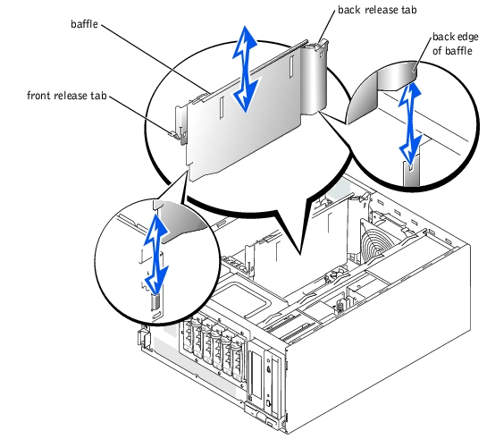
To remove the baffle, lift the release tab at the end of the baffle near the front of the system, press the release tab at the back end of the baffle, and slide the baffle upward.
|
NOTICE: You must reinstall the baffle to maintain proper airflow for system cooling.
|
When you install the baffle, match the triangle and diamond symbols on the release tabs with the corresponding icons on the system chassis. Note the proper position of the back edge of the baffle in Figure 4-5. After aligning both ends of the baffle, slide the baffle into the system until both release tabs lock into place.
The system includes the following system cooling fans:
- Front system fan
- Back system fan
|
|
CAUTION: Only trained service technicians are authorized to remove the system cover and access any of the components inside the system. See the System Information Guide for complete information about safety precautions, working inside the computer, and protecting against electrostatic discharge. |
- Turn off the system, including any attached peripherals, and disconnect the system
from the electrical outlet.
- Remove the bezel (see "Removing the Bezel").
- Remove the cover (see "Removing the Cover").
- Lay the system on its right side.
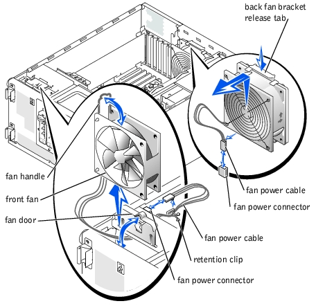
- Disconnect the fan power cable from the fan power connector on the chassis (see
Figure 4-6).
- Remove the fan power cable from the plastic retention clip.
- Open the fan door (see Figure 4-6).
- Pull the wire handle on the fan upward and slide the fan out of the system (see
Figure 4-6).
Figure 4-6. Removing the Front and Back System Fans
|
|
CAUTION: Only trained service technicians are authorized to remove the system cover and access any of the components inside the system. See the System Information Guide for complete information about safety precautions, working inside the computer, and protecting against electrostatic discharge. |
- Insert the fan power cable into the fan bay and connect the fan power cable to the fan
power connector on the chassis (see Figure 4-6).
- Slide the fan into the system (see Figure 4-6), being careful not to trap the power cable
between the fan and chassis.
- Secure the fan power cable with the plastic retention clip (see Figure 4-6).
- Close the fan handle.
- Close the fan door.
- Stand the system upright.
- Install the cover (see "Installing the Cover").
- Install the bezel (see "Installing the Bezel").
- Reconnect the system to its electrical outlet and turn the system on, including any
attached peripherals.
|
|
CAUTION: Only trained service technicians are authorized to remove the system cover and access any of the components inside the system. See the System Information Guide for complete information about safety precautions, working inside the computer, and protecting against electrostatic discharge. |
- Turn off the system, including any attached peripherals, and disconnect the system
from the electrical outlet.
- Remove the bezel (see "Removing the Bezel").
- Remove the cover (see "Removing the Cover").
- Lay the system on its right side.
- Disconnect the fan power cable from the fan power connector on the system board.
To identify system board connectors, see Figure 5-3.
- Pull the fan bracket release tab away from the back panel and slide the fan assembly
upward about 1 cm (0.5 inch) (see Figure 4-6).
- Lift the fan assembly away from the back panel and out of the system.
|
|
CAUTION: Only trained service technicians are authorized to remove the system cover and access any of the components inside the system. See the System Information Guide for complete information about safety precautions, working inside the computer, and protecting against electrostatic discharge. |
- Insert the four tabs on the fan bracket into the mounting holes in the back panel and
slide the fan assembly downward about 1 cm (0.5 inch) until the fan bracket release
tab snaps into place.
- Connect the fan power cable to the fan power connector on the system board.
To identify system board connectors, see Figure 5-3.
- Stand the system upright.
- Install the cover (see "Installing the Cover").
- Install the bezel (see "Installing the Bezel").
- Reconnect the system to its electrical outlet and turn the system on, including any
attached peripherals.
|
|
CAUTION: To prevent risk of personal injury from electrical shock, do not reach into an empty power supply bay. |
|
NOTICE: The power supplies are hot-pluggable. The system requires one power supply to be
installed for the system to operate normally. The system is in the redundant mode when two
power supplies are installed. Remove and replace only one power supply at a time in a system
that is powered on.
|
- Disconnect the power cord from the power supply.
- Using your thumb and index finger, squeeze the catch in the middle of the power
supply handle (see Figure 4-7).
- Rotate the handle downward to release the power supply.
- Slide the power supply out of the system.
Figure 4-7. Removing and Installing an Optional Redundant Power Supply
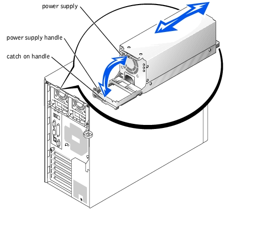
- Slide the power supply into the system.
- When the power supply is fully inserted, rotate the power supply handle upward to
lock the power supply in place.
The power supply will not function until the handle is fully closed.
- Plug the power cable into the power supply, making sure that the cable passes through
the power cable strain relief loop.
 |
NOTE: After installing a new power supply, allow several seconds for the system to
recognize the power supply and determine whether it is working properly. The
power-on indicator turns green to signify that the power supply is functioning properly
(see Figure 3-3).
|
|
|
CAUTION: Only trained service technicians are authorized to remove the system cover and access any of the components inside the system. See the System Information Guide for complete information about safety precautions, working inside the computer, and protecting against electrostatic discharge. |
- Turn off the system, including any attached peripherals, and disconnect the system
from the electrical outlet.
- Remove the bezel (see "Removing the Bezel").
- Remove the cover (see "Removing the Cover").
- Lay the system on its right side.
- Disconnect the power cables from the hard drive(s) or SCSI backplane, diskette drive,
CD drive, and tape drive.
- Disconnect the power cables from the two power connectors labeled P1 and P2 on the
system board.
To locate system board connectors, see Figure 5-3.
- At the back of the system, remove the two hex-head screws that secure the power
supply to the system (see Figure 4-8).
- Carefully slide the power supply out of the system.
Figure 4-8. Removing and Installing a Nonredundant Power Supply
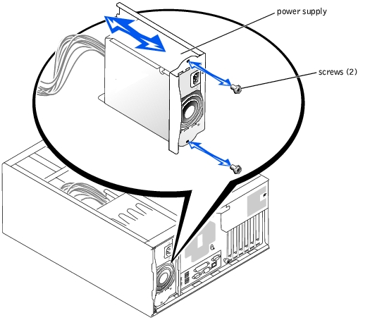
- Slide the power supply into the system.
- Install the two hex-head screws that secure the power supply to the back panel (see
Figure 4-8).
- Connect power cable P1 to the system board connector labeled P1, and connect power
cable P2 to the system board connector labeled P2.
For the location of these system board connectors, see Figure 5-3.
- Connect the power cables to the hard drive(s) or SCSI backplane, diskette drive, CD
drive, and any other installed drive.
- Install the cover (see "Installing the Cover").
- Install the bezel (see "Installing the Bezel").
The power distribution board (PDB) in systems with redundant power supplies serves as an interface between the power supplies and other system components.
|
|
CAUTION: Only trained service technicians are authorized to remove the system cover and access any of the components inside the system. See the System Information Guide for complete information about safety precautions, working inside the computer, and protecting against electrostatic discharge. |
- Turn off the system, including any attached peripherals, and disconnect the system
from the electrical outlet.
- Remove the bezel (see "Removing the Bezel").
- Remove the cover (see "Removing the Cover").
- Lay the system on its right side.
- Remove the redundant power supplies (see "Removing a Redundant Power Supply").
- Disconnect the power cable harness from the top of the PDB (see Figure 4-9).
- Disconnect the three cables from the underside of the PDB.
Figure 4-9. Removing and Installing the Power Distribution Board
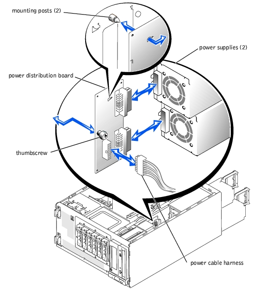
- Loosen the thumbscrew securing the PDB to the system (see Figure 4-9).
- Slide the PDB toward the back of the system and then lift it off of the two mounting
posts on the system.
- Fit the PDB over the two mounting posts on the chassis and slide the board toward the
front of the system.
- Secure the board with the thumbscrew (see Figure 4-9).
- Reconnect the power cables to the PDB:
- Connect the 16-pin connector labeled PDB to the 16-pin connector on the top of
the PDB.
- Connect the 5-pin connector labeled PDB CON to the 5-pin connector on the
underside of the PDB.
- Connect the 24-pin connector labeled P1 to the 24-pin connector on the
underside of the PDB.
- Connect the 8-pin connector labeled P2 to the 8-pin connector on the underside
of the PDB.
- Stand the system upright.
- Install the cover (see "Installing the Cover").
- Install the bezel (see "Installing the Bezel").
The system includes six expansion slots, configured as follows:
- Slots 1 and 2 are 64-bit, 66-MHz PCI slots (3.3 V).
- Slots 3 and 4 are 64-bit, 100-MHz PCI-X slots (3.3 V).
- Slots 5 and 6 are 32-bit, 33-MHz PCI slots (5 V).
All expansion slots accommodate full-length cards, except for slot 1.
To identify the expansion slots and operating speeds, see Figure 5-3.
|
|
CAUTION: Only trained service technicians are authorized to remove the system cover and access any of the components inside the system. See the System Information Guide for complete information about safety precautions, working inside the computer, and protecting against electrostatic discharge. |
|
NOTE: If you install a RAID controller card, install the card in expansion slot 1 or 2.
(See Figure 5-3 to locate these expansion slots.)
|
- Unpack the expansion card, and prepare it for installation.
For instructions, see the documentation that accompanied the card.
- Turn off the system, including any attached peripherals, and disconnect the system
from the electrical outlet.
- Remove the bezel (see "Removing the Bezel").
- Remove the cover (see "Removing the Cover").
- Lay the system on its right side.
- Remove the filler bracket from the expansion slot.
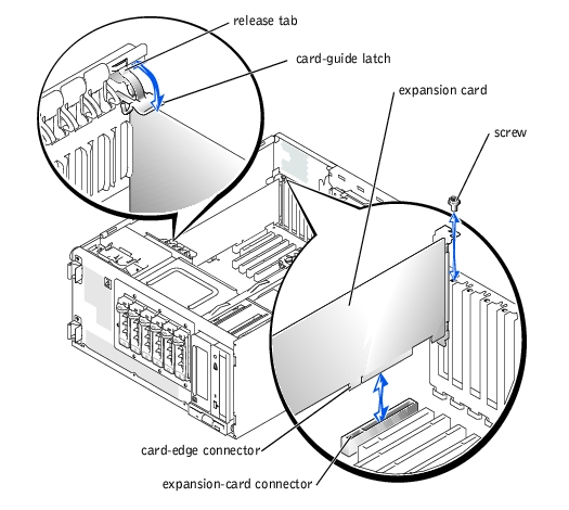
- Install the expansion card (see Figure 4-10):
- Position the expansion card so that the card-edge connector aligns with the
expansion-card connector on the system board.
- Insert the card-edge connector firmly into the expansion-card connector until the
card is fully seated.
- Install the screw that secures the expansion-card bracket to the back panel.
- If the card is a full-length card, close the card-guide latch.
- Connect any cables that should be attached to the card.
See the documentation that accompanied the card for information about its cable connections.
- Stand the system upright.
- Install the cover (see "Installing the Cover").
- Install the bezel (see "Installing the Bezel").
- Reconnect the system to its electrical outlet and turn the system on, including any
attached peripherals.
Figure 4-10. Removing and Installing an Expansion Card
|
|
CAUTION: Only trained service technicians are authorized to remove the system cover and access any of the components inside the system. See the System Information Guide for complete information about safety precautions, working inside the computer, and protecting against electrostatic discharge. |
- Turn off the system, including any attached peripherals, and disconnect the system
from the electrical outlet.
- Remove the bezel (see "Removing the Bezel").
- Remove the cover (see "Removing the Cover").
- Lay the system on its right side.
- Disconnect any cables attached to the card.
- Remove the expansion card (see Figure 4-10):
- If the card is a full-length card, press the release tab on the card-guide latch and
open the latch.
- Remove the screw that secures the expansion-card bracket to the back panel.
- Grasp the expansion card by its top corners, and carefully remove it from the
expansion-card connector.
- If you are removing the card permanently, install a metal filler bracket over the empty
expansion slot opening and close the expansion-card latch.
|
NOTICE: You must install a filler bracket over an empty expansion slot to maintain Federal
Communications Commission (FCC) certification of the system. The brackets also help keep dust
and dirt out of the system and aid in proper cooling and airflow inside the system.
|
- Stand the system upright.
- Install the cover (see "Installing the Cover").
- Install the bezel (see "Installing the Bezel").
- Reconnect the system to its electrical outlet and turn the system on, including any
attached peripherals.
The four memory module connectors on the system board can accommodate from 128 MB to 4 GB of registered memory modules.
System memory is upgradable to 4 GB by installing combinations of 128-, 256-, 512-MB, and 1-GB registered DDR SDRAM modules.
|
NOTICE: The DDR SDRAM memory modules must be PC-266 compliant.
|
Starting with the connector nearest the side of the system board, the memory module sockets are labeled "DIMMA" through "DIMMD" (see Figure 5-3). Follow these guidelines when installing memory modules:
- When you install memory modules, install the first module in connector DIMMA before installing additional modules in connectors DIMMB, DIMMC, and DIMMD.
- Install modules in decreasing order of size, beginning with connector DIMMA.
Table 4-1 lists sample memory configurations based on these guidelines.
Table 4-1. Sample Memory Module Configurations
|
Total Memory
|
DIMMA
|
DIMMB
|
DIMMC
|
DIMMD
|
|---|
128 MB | 128 MB | None | None | None |
512 MB | 256 MB | 256 MB | None | None |
512 MB | 512 MB | None | None | None |
1 GB | 512 MB | 512 MB | None | None |
1.5 GB | 1 GB | 512 MB | None | None |
3 GB | 1 GB | 1 GB | 1 GB | None |
4 GB | 1 GB | 1 GB | 1 GB | 1 GB |
NOTE: This table only lists sample memory module configurations. Not all
possible configurations are listed.
|
|
|
CAUTION: Only trained service technicians are authorized to remove the system cover and access any of the components inside the system. See the System Information Guide for complete information about safety precautions, working inside the computer, and protecting against electrostatic discharge. |
- Turn off the system, including any attached peripherals, and disconnect the system
from the electrical outlet.
- Remove the bezel (see "Removing the Bezel").
- Remove the cover (see "Removing the Cover").
- Lay the system on its right side.
- Install or remove memory modules as necessary to reach the desired memory total (see
"Installing Memory Modules" and "Removing Memory Modules").
See Figure 5-3 to locate the memory module connectors.
- Stand the system upright.
- Install the cover (see "Installing the Cover").
- Install the bezel (see "Installing the Bezel").
- Reconnect the system to its electrical outlet and turn the system on, including any
attached peripherals.
After the system completes the POST routine, it runs a memory test.
The system detects that the new memory does not match the system configuration information, which is stored in NVRAM. The monitor displays an error message that ends with the following words:
Press <F1> to continue; <F2> to enter System Setup
- Press <F2> to enter the System Setup program, and check the System Memory
setting.
The system should have already changed the value in the System Memory setting to reflect the newly installed memory.
- If the System Memory value is incorrect, one or more of the memory modules may not
be installed properly. Repeat step 1 through step 10, ensuring that the memory
modules are firmly seated in their connectors.
- Run the system memory test in the system diagnostics.
|
|
CAUTION: Only trained service technicians are authorized to remove the system cover and access any of the components inside the system. See the System Information Guide for complete information about safety precautions, working inside the computer, and protecting against electrostatic discharge. |
- Turn off the system, including any attached peripherals, and disconnect the system
from the electrical outlet.
- Remove the bezel (see "Removing the Bezel").
- Remove the cover (see "Removing the Cover").
- Lay the system on its right side.
- Locate the memory module connectors in which you will install memory modules (see
Figure 5-3).
- Press down and outward on the memory module connector ejectors, as shown in
Figure 4-11, to allow the memory module to be inserted into the connector.
Figure 4-11. Removing and Installing a Memory Module
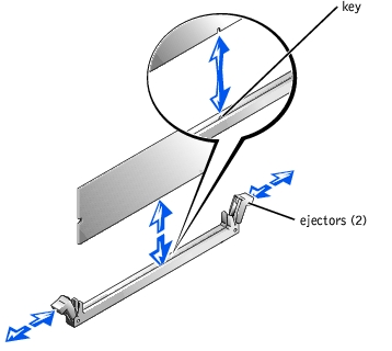
- Align the notch in the memory module's edge connector with the alignment key in the
socket, and insert the memory module in the connector (see Figure 4-11).
The memory module connector has an alignment key that allows the memory module to be installed in the connector in only one way.
- Press down on the memory module with your thumbs while pulling up on the ejectors
with your index fingers to lock the memory module into the connector (see
Figure 4-11).
When the memory module is properly seated in the connector, the memory module connector ejectors should align with the ejectors on the other connectors with memory modules installed.
- Repeat step 5 through step 8 to install the remaining memory modules.
- Perform step 6 through step 12 of "Performing a Memory Upgrade."
|
|
CAUTION: Only trained service technicians are authorized to remove the system cover and access any of the components inside the system. See the System Information Guide for complete information about safety precautions, working inside the computer, and protecting against electrostatic discharge. |
- Turn off the system, including any attached peripherals, and disconnect the system
from the electrical outlet.
- Remove the cover (see "Removing the Cover").
- Lay the system on its right side.
- Locate the memory module connectors from which you will remove memory modules
(see Figure 5-3).
- Press down and outward on the memory module connector ejectors until the memory
module pops out of the connector (see Figure 4-11).
- Repeat step 4 and step 5 of this procedure to remove any other memory modules.
- Perform step 6 through step 12 of "Performing a Memory Upgrade."
Each microprocessor and its associated cache memory are contained in a PGA package that is installed in a ZIF socket on the system board.
|
NOTE: The second microprocessor must be of the same type as the first. If the two
microprocessors are different speeds, both will operate at the speed of the slower
microprocessor.
|
|
|
CAUTION: Only trained service technicians are authorized to remove the system cover and access any of the components inside the system. See the System Information Guide for complete information about safety precautions, working inside the computer, and protecting against electrostatic discharge. |
- Turn off the system, including any attached peripherals, and disconnect the system
from the electrical outlet.
- Remove the bezel (see "Removing the Bezel").
- Remove the cover (see "Removing the Cover").
- Lay the system on its right side.
- If you are removing or installing a microprocessor in socket CPU2, remove the vertical
plastic baffle to improve access to the microprocessor socket (see "Removing the
Baffle").
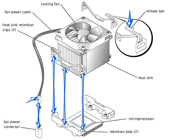
- Disconnect the microprocessor fan cable from the fan power connector on the system
board (see Figure 4-12).
To identify system board connectors, see Figure 5-3.
- Remove the back system fan (see "Removing the Back System Fan").
|
|
CAUTION: The microprocessor and heat sink can become extremely hot. Be sure they have had sufficient time to cool before handling. |
|
NOTICE: Do not operate the system without the fan and heat-sink assembly installed. The
assembly is required to maintain proper thermal conditions.
|
|
NOTICE: After removing the fan and heat-sink assembly, place it upside down on a flat surface
to prevent the thermal interface material on the heat sink from being damaged or contaminated.
|
|
NOTICE: The microprocessor fan and heat sink are constructed together as a single assembly.
Do not attempt to remove the fan from the heat sink.
|
- Remove the microprocessor fan and heat-sink assembly (see Figure 4-12):
- Press down on the release tabs on the heat-sink retention clips to release the clips
from the retaining tabs on the ZIF socket.
- Lift the assembly away from the microprocessor.
Figure 4-12. Removing the Microprocessor Fan and Heat-Sink Assembly
- Pull the microprocessor socket release lever upward to the fully open position (see
Figure 4-13).
|
NOTICE: Be careful not to bend any of the pins when removing the microprocessor. Bending
the pins can permanently damage the microprocessor.
|
- Lift the microprocessor out of the socket and leave the release lever in the open
position so that the socket is ready for the new microprocessor (see Figure 4-13).
Figure 4-13. Removing and Installing a Microprocessor

- Unpack the new microprocessor.
- Ensure that the microprocessor socket release lever is in the fully open position.
|
NOTICE: The microprocessor and system board can be damaged if the microprocessor socket
release lever is not fully open when you insert the new microprocessor.
|
- Align pin 1 on the microprocessor with pin 1 on the microprocessor socket (see
Figure 4-13).
|
NOTICE: Positioning the microprocessor incorrectly can permanently damage the
microprocessor and the system when you turn on the system. When placing the microprocessor
in the socket, be sure that all of the pins on the microprocessor go into the corresponding holes
and that the processor is parallel to the surface of the socket. Be careful not to bend the pins.
|
- Install the microprocessor in the socket (see Figure 4-13).
|
NOTE: No force is needed to install the microprocessor in the socket. When the
microprocessor is aligned correctly, it should drop into the socket.
|
- When the microprocessor is fully seated in the socket, rotate the socket release lever
back down until it snaps into place, securing the microprocessor in the socket.
- Place the microprocessor fan and heat-sink assembly on top of the microprocessor (see
Figure 4-12).
- To reinstall the heat-sink retention clips, hold the clip by the release tab (see
Figure 4-12), fit the opposite end of the clip over the retention tab on the
microprocessor socket, and press down on the release tab until the free end of the clip
snaps into place.
|
NOTICE: The cooling fan must be connected for the microprocessor to maintain proper thermal
conditions.
|
- Connect the microprocessor fan cable to the fan connector on the system board (see
Figure 4-12).
To identify system board connectors, see Figure 5-3.
- Reinstall the back system fan (see "Installing the Back System Fan").
|
NOTICE: You must reinstall the baffle to maintain proper airflow for system cooling.
|
- If you removed the baffle in step 5, replace the baffle now (see "Installing the Baffle").
- Stand the system upright.
- Install the cover (see "Installing the Cover").
- Install the bezel (see "Installing the Bezel").
- Reconnect the system to its electrical outlet and turn the system on, including any
attached peripherals.
- Enter the System Setup program, and ensure that the microprocessor options match
the new system configuration (see "Using the System Setup Program").
As the system boots, it detects the presence of the new microprocessor and automatically changes the system configuration information in the System Setup program. A message similar to the following appears:
One 1.8 GHz Processor, Processor Bus: 400 MHz, L2 cache
512 KB Advanced
- Confirm that the top line of the system data area in the System Setup program
correctly identifies the installed microprocessor(s) (see "Using the System Setup
Program").
- Exit the System Setup program.
- Run the system diagnostics to verify that the new microprocessor is operating
correctly.
|
|
CAUTION: Only trained service technicians are authorized to remove the system cover and access any of the components inside the system. See the System Information Guide for complete information about safety precautions, working inside the computer, and protecting against electrostatic discharge. |
- Turn off the system, including any attached peripherals, and disconnect the system
from the electrical outlet.
- Remove the bezel (see "Removing the Bezel").
- Remove the cover (see "Removing the Cover").
- Lay the system on its right side.
- Remove the SCSI hard drives (see "Installing and Removing Hot-Plug SCSI Hard
Drives").
- Remove the expansion cards (see "Removing an Expansion Card").
- Disconnect the power cable and SCSI interface cable from the SCIS backplane board.
- Remove the hard-drive bay (see Figure 4-14):
- Loosen the four hex-head screws that secure the drive bay in the system.
- Slide the drive bay out of the system.
- Remove the SCSI backplane board from the drive bay (see Figure 4-14):
- Loosen the thumbscrew on the board.
- Slide the board horizontally until it is disengaged from the retention hooks on the
drive bay, and then lift the board away from the drive bay.
Figure 4-14. Removing and Installing the SCSI Backplane Board
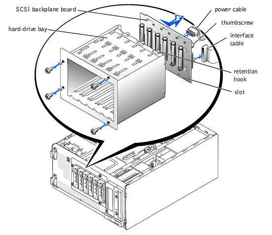
- Attach the SCSI backplane board to the drive bay:
- Fit the backplane onto the back of the drive bay so that the retention hooks fit
through the corresponding slots in the backplane board.
- Slide the backplane horizontally to engage the retention hooks.
- Secure the backplane to the drive bay with the thumbscrew.
- Install the hard-drive bay in the system (see Figure 4-23):
- With the side of the drive bay labeled "Top" facing toward the external drive bays,
slide the drive bay into the system.
- Replace the four screws that secure the drive bay in the system.
- Connect the power and interface cables to the backplane.
- Replace the expansion cards (see "Installing an Expansion Card").
- Stand the system upright.
- Install the cover (see "Installing the Cover").
- Install the bezel (see "Installing the Bezel").
- Install the hard drives (see "Installing and Removing Hot-Plug SCSI Hard Drives").
|
NOTE: To maintain Federal Communications Commission (FCC) certification of the
system, all drive bays should contain a hard drive or empty hard-drive carrier.
|
- Reconnect the system to its electrical outlet and turn the system on, including any
attached peripherals.
|
|
CAUTION: See the System Information Guide for complete information about safety precautions, working inside the computer, and protecting against electrostatic discharge. |
- Turn off the system, including any attached peripherals, and disconnect the system
from the electrical outlet.
- Remove the bezel (see "Removing the Bezel").
- Remove the screw securing the control panel to the front of the system (see
Figure 4-15).
- Use a small pair of needle-nose pliers to compress the tabs on each of the plastic
standoffs, and then pull the control panel straight out from the system to disconnect
the connector on the back of the board.
Figure 4-15. Removing and Installing the Control Panel
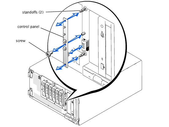
- Align the eight-pin connector on the back of the control panel with the matching
connector on the system, and press the control panel onto the two plastic standoffs.
- Secure the control panel with the screw.
- Install the bezel (see "Installing the Bezel").
- Reconnect the system to its electrical outlet and turn the system on, including any
attached peripherals.
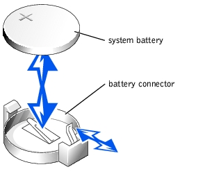
The system battery is a 3-V, coin-cell battery.
|
|
CAUTION: Only trained service technicians are authorized to remove the system cover and access any of the components inside the system. See the System Information Guide for complete information about safety precautions, working inside the computer, and protecting against electrostatic discharge. |
|
|
CAUTION: There is a danger of a new battery exploding if it is incorrectly installed. Replace the battery only with the same or equivalent type recommended by the manufacturer. Discard used batteries according to the manufacturer's instructions. See the System Information Guide for additional information. |
- Turn off the system, including any attached peripherals, and disconnect the system
from the electrical outlet.
- Remove the cover (see "Removing the Cover").
- Lay the system on its right side.
- If necessary, remove the expansion cards to access the battery socket (see "Removing
an Expansion Card").
- Remove the system battery (see Figure 4-16).
See Figure 5-3 to locate the system battery on the system board. You can pry the system battery out of its connector with your fingers or with a blunt, nonconductive object such as a plastic screwdriver.
- Install the new system battery with the side labeled "+" facing up (see Figure 4-16).
- If you removed expansion cards in step 4, replace them now (see "Installing an
Expansion Card").
- Stand the system upright.
- Install the cover (see "Installing the Cover").
- Install the bezel (see "Installing the Bezel").
- Reconnect the system to its electrical outlet and turn the system on, including any
attached peripherals.
Figure 4-16. Installing the System Battery
- Enter the System Setup program to confirm that the battery is operating properly (see
"Using the System Setup Program").
- Enter the correct time and date in the System Setup program's Time and Date fields.
- Exit the System Setup program.
- To test the newly installed battery, turn off the system and disconnect it from the
electrical outlet for at least an hour.
- After an hour, reconnect the system to its electrical outlet and turn it on.
- Enter the System Setup program and if the time and date are not correct, replace the
system board.
Most interface connectors are keyed for correct insertion. When you disconnect an interface cable, take care to grasp the cable connector, rather than the cable itself, to avoid stress on the cable.
The system can accommodate many different drive configurations, each with specific cable requirements. Table 4-2 shows the cable requirements for common drive configurations.
Table 4-2. Drive Cable Configuration
|
Drives
|
Required Cable
|
Cable Connections
|
|---|
IDE CD drive, DVD drive, or combination drive (See Figure 4-20.) | 40-pin IDE 2-drop cable | IDE drive and secondary IDE connector on system board |
Up to two IDE hard drives (See Figure 4-24.) | 80-pin IDE 2-drop cable | IDE hard drives and primary IDE connector on system board |
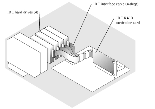
Three or four IDE hard drives (See Figure 4-27.) | 80-pin IDE bundled 4-drop cable | IDE hard drives and CERC IDE RAID controller card |
Up to four non-hot-plug SCSI hard-drives (See Figure 4-25 and Figure 4-26.) | 66-cm (26-inch) or 94-cm (37-inch) 68-pin SCSI 4-drop cable (terminated) | 66-cm (26-inch) cable to SCSI hard drives and SCSI controller on system board (See Figure 4-25.)
or
94-cm (37-inch) cable to SCSI hard drives and SCSI RAID controller card (See Figure 4-26.) |
Up to six hot-plug SCSI hard drives (See Figure 4-28 and Figure 4-29.) | 38-cm (15-inch) or 63-cm (25-inch) 68-pin SCSI 1-drop cable (unterminated) | 38-cm (15-inch) cable to SCSI backplane and SCSI connector on system board (See Figure 4-28.)
or
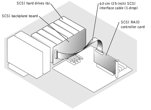
63-cm (25-inch) cable to SCSI backplane and RAID controller card (See Figure 4-29.) |
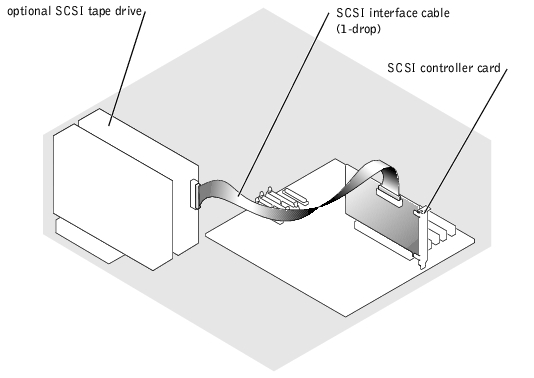
SCSI tape drive (See Figure 4-21 and Figure 4-22.) | 68-pin SCSI 1-drop cable (terminated) | SCSI tape drive and SCSI controller on system board (See Figure 4-21.)
or
SCSI tape drive and SCSI controller card if SCSI controller is used for SCSI hard drives (See Figure 4-22.) |
The 3.5-inch diskette drive, 5.25-inch devices, and non-hot-plug hard drives must connect to a DC power cable from the system power supply. (Hot-plug SCSI drives obtain their power from the optional SCSI backplane.)
The IDE subsystem provides two channels (primary and secondary). Each channel can support up to two IDE drives such as high-capacity hard drives, CD drives, DVD drives, and tape drives.
Each IDE drive should be configured for the Cable Select setting, which assigns master and slave status to a drive according to its position on the interface cable. In this configuration, the drive attached to the last connector on the interface cable is the master or boot drive (drive 0) and the drive attached to the middle connector on the interface cable is the slave drive (drive 1). See the drive's documentation for instructions on configuring the Cable Select setting.
Table 4-3 lists guidelines for installing IDE drives connected to the IDE system board connectors.
Table 4-3. IDE Drive Configuration Guidelines
|
IDE Channel
|
System Board Connector
|
Drive Type(s)
|
|---|
1 | PRIMARY IDE | IDE hard drives (or optional DRACII/XT card [when supported]) |
2 | SECONDARY IDE | IDE CD, DVD, tape, or combination drives |
NOTE: The configurations shown in this table describe IDE drives connected directly to the IDE
system board connectors. To identify system board connectors, see Figure 5-3.
|
Although SCSI drives are installed in essentially the same way as other drives, their configuration requirements are different. To install and configure a SCSI drive, follow the guidelines in the following subsections.
SCSI interface connectors are keyed for correct insertion. Keying ensures that the pin-1 wire in the cable connects to pin 1 in the connectors on both ends. When you disconnect an interface cable, take care to grasp the cable connector, rather than the cable itself, to avoid stress on the cable.
Each drive attached to a SCSI controller must have a unique SCSI ID number from 0 to 15.
- The SCSI hard drive from which the system boots is configured as SCSI ID 0.
- A SCSI tape drive is typically configured as SCSI ID 6.
- If you install optional SCSI drives or change the SCSI configuration, see the documentation for each SCSI drive for information on setting the appropriate SCSI ID number.
|
NOTE: There is no requirement that SCSI ID numbers be assigned sequentially or that
drives be attached to the cable in order by ID number.
|
The SCSI bus requires that termination be enabled at opposite ends of the SCSI chain and disabled for all drives in between. For internal SCSI drives, termination is configured automatically. See the documentation provided with any optional SCSI drive you purchase for information on disabling termination.
The drive or device from which the system boots is determined by the boot order specified in the System Setup program (see "Using the System Setup Program"). To boot the system from a hard drive or drive array, the drive(s) must be connected to the appropriate controller:
- To boot from a single IDE hard drive, the master drive (drive 0) must be connected to the primary controller on the system board. To identify system board connectors, see Figure 5-3.
- To boot from a single SCSI hard drive, the drive must be connected to the SCSI controller.
- To boot from an IDE or SCSI RAID array, the drive must be connected to the RAID controller card (see the documentation that accompanied the controller card).
|
|
CAUTION: Only trained service technicians are authorized to remove the system cover and access any of the components inside the system. See the System Information Guide for complete information about safety precautions, working inside the computer, and protecting against electrostatic discharge. |
- Turn off the system, including any attached peripherals, and disconnect the system
from the electrical outlet.
- Remove the bezel (see "Removing the Bezel").
- Remove the cover (see "Removing the Cover").
- Lay the system on its right side.
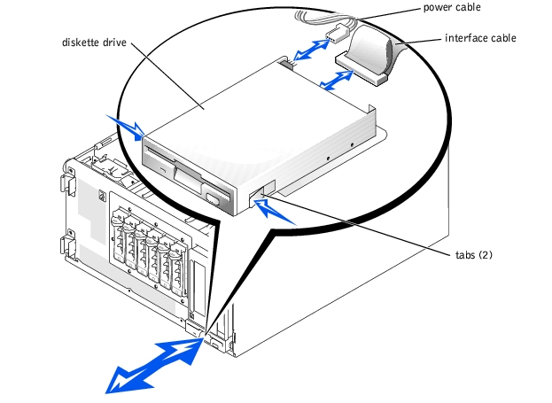
- Use your thumb and index finger to press the tabs that secure the diskette drive in the
drive bay (see Figure 4-17).
- Slide the diskette drive forward out of the drive bay.
- Disconnect the power cable and the interface cable from the diskette drive.
Figure 4-17. Removing a Diskette Drive
|
|
CAUTION: Only trained service technicians are authorized to remove the system cover and access any of the components inside the system. See the System Information Guide for complete information about safety precautions, working inside the computer, and protecting against electrostatic discharge. |
- Connect the power cable and the interface cable to the diskette drive.
- Slide the diskette drive into the externally accessible drive bay (see Figure 4-7).
- Stand the system upright.
- Install the cover (see "Installing the Cover").
- Install the bezel (see "Installing the Bezel").
- Reconnect the system to its electrical outlet and turn the system on, including any
attached peripherals.
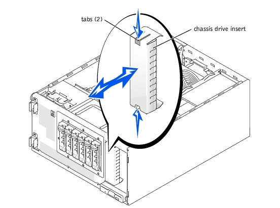
To help keep dust and dirt out of the system, a plastic insert in the bezel covers each empty external drive bay. Additionally, each empty external drive bay is covered by a metal insert in the chassis to maintain to maintain Federal Communications Commission (FCC) certification of the system.
Before you install a 5.25-inch drive in an empty external drive bay, you must first remove both drive inserts. If you remove a 5.25-inch drive permanently, you must install both the chassis and bezel inserts.
|
|
CAUTION: Only trained service technicians are authorized to remove the system cover and access any of the components inside the system. See the System Information Guide for complete information about safety precautions, working inside the computer, and protecting against electrostatic discharge. |
- Turn off the system, including any attached peripherals, and disconnect the system
from the electrical outlet.
- Remove the bezel (see "Removing the Bezel").
- Remove the cover (see "Removing the Cover").
- Remove the bezel drive insert:
- From inside the bezel, press the tabs at each end of the insert inward with your
thumbs.
- Pull the insert out of the bezel.
- Remove the chassis drive insert (see Figure 4-18):
- Press the tabs at each end of the insert inward.
- Pull the insert out of the chassis.
Figure 4-18. Removing the Chassis Drive Insert
|
|
CAUTION: Only trained service technicians are authorized to remove the system cover and access any of the components inside the system. See the System Information Guide for complete information about safety precautions, working inside the computer, and protecting against electrostatic discharge. |
|
NOTICE: You must install both inserts in an empty 5.25-inch drive bay to maintain Federal
Communications Commission (FCC) certification of the system. The inserts also help keep dust
and dirt out of the system.
|
- Install the chassis drive insert by sliding the insert into the chassis until the tabs on the
side of the insert snap into place (see Figure 4-18).
- Install the bezel drive insert by sliding the insert into the bezel until the tabs on the
side of the insert snap into place.
- Install the cover (see "Installing the Cover").
- Install the bezel (see "Installing the Bezel").
- Reconnect the system to its electrical outlet and turn the system on, including any
attached peripherals.
A CD drive, DVD drive, or combination drive is standard in the first external drive bay, and an additional drive of your choice can be installed in the second external drive bay. These drives connect either to the system board or to an optional controller card.
|
|
CAUTION: Only trained service technicians are authorized to remove the system cover and access any of the components inside the system. See the System Information Guide for complete information about safety precautions, working inside the computer, and protecting against electrostatic discharge. |
- Unpack the drive (and controller card, if applicable), and prepare the drive for
installation.
For instructions, see the documentation that accompanied the drive. Also, see "IDE Configuration Information" or "SCSI Configuration Information" for information on configuring the drive.
- Turn off the system, including any attached peripherals, and disconnect the system
from the electrical outlet.
- Remove the front-panel inserts for the empty external drive bay (see "Removing the
Front-Panel Drive Inserts").
- Lay the system on its right side.
- If the drive was supplied with a controller card, install the controller card in an
expansion slot (see "Installing an Expansion Card").
- Slide the drive into the external drive bay.
- Install the screws that secure the drive in the drive bay (see Figure 4-19).
Figure 4-19. Installing a 5.25-Inch Drive
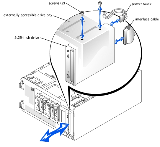
- Connect a DC power cable connector to the drive's power input connector (see
Figure 4-19).
- Connect the interface cable to the drive (see Figure 4-19) and to the system board or
controller card:
- Figure 4-20 illustrates a common cable configuration for externally accessible IDE drives.
- Figure 4-21 illustrates a SCSI tape drive connected to the SCSI controller on the system board.
- Figure 4-22 shows a SCSI tape drive connected to a SCSI controller card.
If necessary, temporarily remove the baffle to allow easier routing of the interface cable (see "Removing the Baffle").
For information about the controller card, see the documentation that accompanied the card.
Figure 4-20. Connecting an IDE CD Drive and Optional IDE Tape Drive to the Integrated IDE Controller
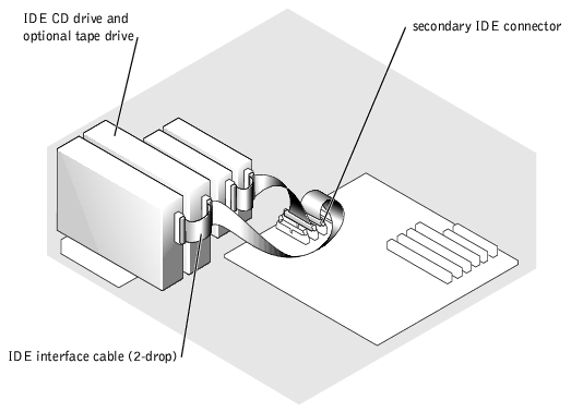
Figure 4-21. Connecting a SCSI Tape Drive to the Integrated SCSI Controller
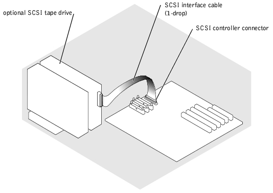
Figure 4-22. Connecting a SCSI Tape Drive to a SCSI Controller Card
- Ensure that all cables are firmly connected and arranged so that they will not catch on
the system covers or block airflow inside the system.
- If you removed the baffle in step 9, replace the baffle now (see "Installing the Baffle").
- Stand the system upright.
- Install the cover (see "Installing the Cover").
- Install the bezel (see "Installing the Bezel").
- Reconnect the system to its electrical outlet and turn the system on, including any
attached peripherals.
- Test the drive:
- If you installed an IDE drive, run the IDE devices tests in the system diagnostics to determine whether the tape drive operates properly (see "Running the System Diagnostics").
- If you installed a SCSI drive, run the SCSI controllers test in the system diagnostics (see "Running the System Diagnostics").
- If you installed a tape drive, see the tape drive software documentation to perform a backup and verification test.
You can install up to four non-hot-plug IDE or SCSI hard drives in a removable drive bay or up to six hot-plug SCSI hard drives connected to the optional SCSI backplane.
Use the following guidelines when installing hard drives:
- You should use only drives tested and approved for use in the system.
- You may need to use different programs than those provided with the operating system to partition and format a hard drive. See the hard drive's documentation for information on setting up the drive.
- When you format a high-capacity hard drive, allow enough time for the formatting to be completed. Long format times for these drives are normal. For example, a large drive can take over an hour to format.
- Do not turn off or reboot the system while the drive is being formatted. Doing so can cause a drive failure.
The SCSI controller on the system board supports integrated mirroring (RAID 1) of two SCSI drives. Both hot-plug and non-hot-plug drives can be mirrored.
Follow these guidelines to implement integrated mirroring on the system:
- If you have more than two SCSI hard drives connected to the SCSI controller on the system board, only two drives can be mirrored. Any remaining drives connected to the controller will function as conventional SCSI drives without data redundancy.
- Connect the drives to the SCSI controller as described in "Installing and Removing Hot-Plug SCSI Hard Drives" or "Installing and Removing Non-Hot-Plug Hard Drives."
- After installing the drives, use the system's array management software to configure the drives. See the array management software documentation for instructions on creating virtual disks on the mirrored drives.
|
NOTE: Dell strongly recommends that you use Dell OpenManage™ Array Manager to
configure integrated mirroring for systems using the Windows operating system. If
your system uses the Linux operating system, run the PER4/im BIOS Configuration
Utility by pressing <Ctrl><M> when prompted during system boot.)
|
For more information on this feature, see the integrated mirroring documentation provided with the system.
|
|
CAUTION: Only trained service technicians are authorized to remove the system cover and access any of the components inside the system. See the System Information Guide for complete information about safety precautions, working inside the computer, and protecting against electrostatic discharge. |
- Turn off the system, including any attached peripherals, and disconnect the system
from the electrical outlet.
- Remove the cover (see "Removing the Cover").
- Remove the bezel (see "Removing the Bezel").
- Lay the system on its right side.
- Disconnect all power cables and interface cables from the hard drives in the drive bay.
- Remove the hard-drive bay (see Figure 4-23):
- Loosen the four Phillips-head screws that secure the drive bay in the system.
- Slide the drive bay out of the system.
- If you are removing a drive, remove the drive from the drive bay (see Figure 4-23):
- Remove the two screws that secure the drive in the drive bay.
- Slide the drive out of the drive bay.
Figure 4-23. Removing and Installing a Non-Hot-Plug Hard Drive
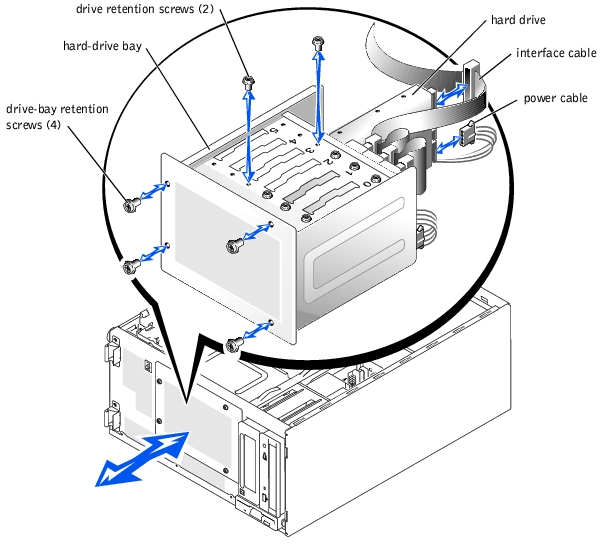
- Install the hard-drive bay (see Figure 4-23):
- With the side of the drive bay labeled "Top" facing toward the external drive bays,
slide the drive bay into the system.
- Replace the four screws that secure the drive bay in the system.
- Connect all power cables and interface cables to the hard drives remaining in the
drive bay.
- Stand the system upright.
- Install the cover (see "Installing the Cover").
- Install the bezel (see "Installing the Bezel").
- Reconnect the system to its electrical outlet and turn the system on, including any
attached peripherals.
|
|
CAUTION: Only trained service technicians are authorized to remove the system cover and access any of the components inside the system. See the System Information Guide for complete information about safety precautions, working inside the computer, and protecting against electrostatic discharge. |
- Unpack the drive (and controller card, if applicable), and prepare the drive for
installation.
For instructions, see the documentation that accompanied the drive. Also, see "IDE Configuration Information" or "SCSI Configuration Information" for information on configuring the drive.
- Turn off the system, including any attached peripherals, and disconnect the system
from the electrical outlet.
- Remove the bezel (see "Removing the Bezel").
- Remove the cover (see "Removing the Cover").
- Lay the system on its right side.
- If the drive was supplied with a controller card, install the controller card in an
expansion slot (see "Installing an Expansion Card").
- Disconnect all power cables and interface cables from the hard drives in the drive bay.
- Remove the hard-drive bay (see Figure 4-23):
- Loosen the four Phillips-head screws that secure the drive bay in the system.
- Slide the drive bay out of the system.
- Install the drive in the drive bay (see Figure 4-23):
- Slide the drive into the drive bay with the back of the drive toward the back of the
drive bay.
- Install the two screws that secure the drive in the drive bay.
- Install the hard-drive bay (see Figure 4-23):
- With the side of the drive bay labeled "Top" facing toward the external drive bays,
slide the drive bay into the system.
- Replace the four screws that secure the drive bay in the system.
- Connect a DC power cable connector to the drive's power input connector.
- Connect the interface cable connector to the drive's interface connector:
- If you are installing one or two IDE hard drives, connect the interface cable between the drive(s) and the system board (see Figure 4-24).
- If you are installing one or more SCSI hard drives, connect the interface cable to the drive(s) and the SCSI controller on the system board (see Figure 4-25).
- If you are installing drives in an IDE or SCSI RAID array, connect the interface cable to the drives and the optional RAID controller card (see Figure 4-27 or Figure 4-28).
If necessary, temporarily remove the baffle to allow easier routing of the interface cable (see "Removing the Baffle").
For information about the controller card, see the documentation that accompanied the card.
Figure 4-24. Connecting IDE Hard Drives to the Integrated IDE Controller
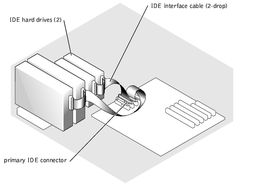
Figure 4-25. Connecting Non-Hot-Plug SCSI Hard Drives to the Integrated SCSI Controller
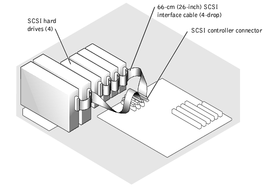
Figure 4-26. Connecting Non-Hot-Plug SCSI Hard Drives to an Optional SCSI RAID Controller Card
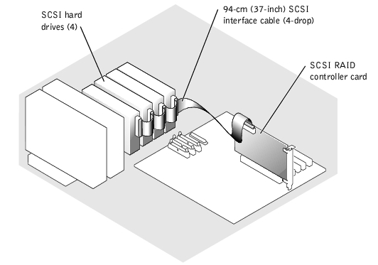
Figure 4-27. Connecting IDE Hard Drives to an Optional IDE RAID Controller Card
- Connect all power cables and interface cables to the other hard drives in the drive bay.
- Ensure that all cables are firmly connected and arranged so that they will not catch on
the system covers or block airflow inside the system.
- If you removed the baffle in step 12, replace the baffle now (see "Installing the
Baffle").
- Stand the system upright.
- Install the cover (see "Installing the Cover").
- Install the bezel (see "Installing the Bezel").
- Reconnect the system to its electrical outlet and turn the system on, including any
attached peripherals.
|
NOTICE: Do not turn off or reboot the system while the drive is being formatted. Doing so
may cause a drive failure.
|
- Partition and logically format the hard drive (see the operating system
documentation).
- Test the drive:
- If you installed one or more IDE hard drives connected to the IDE controller on the system board, run the hard drive tests in the system diagnostics to determine whether the drive operates properly (see "Running the System Diagnostics").
- If you installed a drive in an IDE RAID array, run the hard drive tests in the system diagnostics (see "Running the System Diagnostics"). Also, see the RAID controller's documentation for information on testing the controller.
- If you installed one or more SCSI hard drives connected to the SCSI controller on the system board, run the SCSI controllers tests and the hard drive tests in the system diagnostics (see "Running the System Diagnostics").
- If you installed a drive in a SCSI RAID array, run the SCSI controllers tests and the hard drive tests in the system diagnostics (see "Running the System Diagnostics"). Also, see the RAID controller's documentation for information on testing the array.
The drive bays in a system with an optional SCSI backplane board provide space for up to six 1-inch hard drives. The hard drives plug into the SCSI backplane board, which is connected to a controller on the system board (see Figure 4-28) or to a RAID controller card (see Figure 4-29).
Figure 4-28. Hot-Plug SCSI Hard Drives Connected to the Integrated SCSI Controller
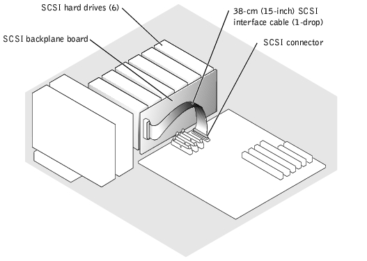
Figure 4-29. Hot-Plug SCSI Hard Drives Connected to a RAID Controller Card
|
NOTICE: Not all operating systems support hot-plug drive installation. See the documentation
supplied with the operating system.
|
- Remove the bezel (see "Removing the Bezel").
- Take the hard drive offline and wait until the hard-drive indicator codes on the drive
carrier signal that the drive can be removed safely (see Table 3-5).
If the drive has been online, the drive-status indicator will blink green two times per second as the drive is powered down. When all indicators are off, the drive is ready for removal.
See the operating system documentation for more information on taking the hard drive offline.
- Open the hard-drive carrier handle to release the drive (see Figure 4-30).
Figure 4-30. Removing and Installing a Hot-Plug Hard-Drive
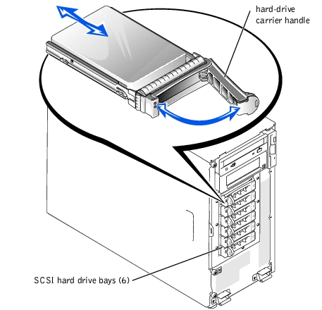
- Slide the hard drive out until it is free of the drive bay (see Figure 4-30).
|
NOTE: To maintain Federal Communications Commission (FCC) certification of the
system, all drive bays should contain a hard drive or empty hard drive carrier.
|
- Replace the drive with another drive, or an empty drive carrier (see "Installing a Hot-
Plug Hard Drive").
- Replace the bezel (see "Installing the Bezel").
|
NOTICE: Not all operating systems support hot-plug drive installation. See the documentation
supplied with the operating system.
|
- Remove the bezel (see "Removing the Bezel").
- Open the hard-drive carrier handle (see Figure 4-30).
|
NOTICE: Do not insert a hard-drive carrier and attempt to lock its handle next to a partially
installed carrier. Doing so can damage the partially installed carrier's shield spring and make it
unusable. Ensure that the adjacent drive carrier is fully installed.
|
- Insert the hard-drive carrier into the drive bay (see Figure 4-30).
- Close the hard-drive carrier handle to lock it in place.
- Replace the bezel (see "Installing the Bezel").
- Install any required SCSI device drivers.
- If the hard drive is new, run the SCSI controllers test in the system diagnostics.
Follow this general procedure when installing a RAID controller card. For specific instructions, see the documentation supplied with the card.
|
|
CAUTION: Only trained service technicians are authorized to remove the system cover and access any of the components inside the system. See the System Information Guide for complete information about safety precautions, working inside the computer, and protecting against electrostatic discharge. |
|
NOTICE: If you are adding a RAID controller card to a system that previously used integrated
mirroring, use the PERC4/im BIOS Configuration Utility to "break" the mirroring before
installing the RAID controller card. To run the utility, press <Ctrl><M> when
prompted during system boot.
|
- Unpack the expansion card, and prepare it for installation.
For instructions, see the documentation that accompanied the card.
- Turn off the system, including any attached peripherals, and disconnect the system
from the electrical outlet.
- Remove the bezel (see "Removing the Bezel").
- Remove the cover (see "Removing the Cover").
- Lay the system on its right side.
- Install the controller card in expansion slot 1 or 2 (see "Installing an Expansion Card").
- Connect the interface cable to the card and to the drives.
See Figure 4-26, Figure 4-28, and the documentation that accompanied the card for information about cable connections between the drives and RAID card.
- Stand the system upright.
- Install the cover (see "Installing the Cover").
- Install the bezel (see "Installing the Bezel").
- Reconnect the system to its electrical outlet and turn the system on, including any
attached peripherals.
- Ensure that any required device drivers are installed and are configured correctly.
For information on installing device drivers, see the Dell OpenManage Server Assistant CD and the documentation that accompanied the controller card.
- Test the array:
Also, see the RAID controller's documentation for information on testing the array.
See "Running the System Diagnostics" for information on running the diagnostics and troubleshooting any problems that may occur.
|
|
CAUTION: Only trained service technicians are authorized to remove the system cover and access any of the components inside the system. See the System Information Guide for complete information about safety precautions, working inside the computer, and protecting against electrostatic discharge. |
- Turn off the system, including any attached peripherals, and disconnect the system
from the electrical outlet.
- Remove the bezel (see "Removing the Bezel").
- Remove the cover (see "Removing the Cover").
- Lay the system on its right side.
- Remove the baffle (see "Removing the Baffle").
- Remove the expansion cards (see "Removing an Expansion Card").
- Remove the memory modules (see "Removing Memory Modules").
- Remove the microprocessor(s) (see "Microprocessors").
- Disconnect all cables attached to the system board.
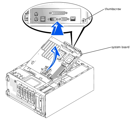
- Remove the system board (see Figure 4-31):
- Loosen the thumbscrew on the I/O panel at the back of the system.
- Slide the system board and its mounting plate away from the back panel about 2.5
cm (1 inch).
- Tilt the back of the system board up, and carefully lift it out of the system (see
Figure 4-31).
Figure 4-31. Installing the System Board
|
|
CAUTION: Only trained service technicians are authorized to remove the system cover and access any of the components inside the system. See the System Information Guide for complete information about safety precautions, working inside the computer, and protecting against electrostatic discharge. |
|
NOTICE: Do not install memory modules on the new system board before installing the board.
|
- Replace the system board (see Figure 4-31):
|
NOTICE: Use care when lowering the front of the system board. You must first position the
front edge of the board beneath the hard drive bay and then lower the back of the board.
|
- Lower the system board, front end first, into the system.
- Slide the system board back (toward the back panel) until the thumbscrew on the
I/O panel can be tightened to secure the system board in place (see Figure 4-31).
- Connect power cable P1 to the system board connector labeled P1, and connect power
cable P2 to the system board connector labeled P2.
- Connect the following cables to the system board, as applicable:
- Control panel
- PDB
- Front fan
- Chassis intrusion switch
- IDE hard drives
- IDE CD or tape drive
- Diskette drive
- SCSI hard drives
- Install the microprocessor (see "Microprocessors").
- Replace the back cooling fan (see "System Fans").
- Install the memory modules (see "Installing Memory Modules").
- Install all expansion cards that were removed (see "Installing an Expansion Card").
- Replace the baffle (see "Installing the Baffle").
- Replace the cover (see "Installing the Cover").
- Install the bezel (see "Installing the Bezel").
- Reconnect the system to its electrical outlet and turn the system on, including any
attached peripherals.
Back to Contents Page
