Back to Contents Page
Removing and Replacing Parts
Dell™ PowerEdge™ 1650 Systems Service Manual
The procedures in this guide require that you open or remove the cover
and work inside the system. While working inside the system, do not attempt to
service the system except as explained in this manual and elsewhere in system documentation. Always follow the instructions closely. Make sure to review all
of the procedures in "Safety Instructions" in your System Information
document.
This section provides servicing procedures for components inside the system. Before you
start any of the procedures in this section, perform the following tasks:
When there is no replacement procedure provided, use the removal procedure in
reverse order to install the replacement part.
Recommended Tools
You need the following to perform the procedures in this section:
- The system diagnostics diskette set appropriate for your system
- Key to the system keylock
- #1 and #2 Phillips screwdriver
- Wrist grounding strap
The optional front bezel has system status indicators. A lock on the bezel restricts
access to the power button, diskette drive, CD drive, hard drive(s), and the
interior of the system.
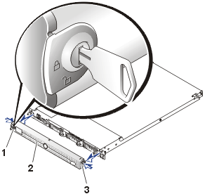
- To remove the bezel, use the system key to unlock the keylock on the
bezel, press the tab at each end of the bezel, and then pull the bezel away
from the system (see Figure 1).
- To replace the front bezel, fit the tabs on the bezel into the
corresponding slots in the front panel and lock the keylock.
Figure 1. Removing and Replacing the
Optional Front Bezel
 |
| 1 |
Keylock |
| 2 |
Front bezel |
| 3 |
Tabs (2) |
|
Two doors on the top of the system provide access to the system board and
other internal components.
To open the system doors, perform the following steps:
- Observe the safety instructions in the System Information
document.
- Remove the optional front bezel, if it is installed.
- If the system is installed in a rack, loosen the front-panel thumbscrews that secure the system to the
rack cabinet, and slide the system out of the rack to the slide assembly's fully
extended position.
- If the optional security screw is installed on the system cover, remove it
now.
Figure 2. Opening the System Doors
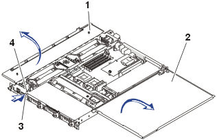 |
| 1 |
Left door |
| 2 |
Right door |
| 3 |
Latch |
| 4 |
Optional security screw |
|
- Press the latch on the system front panel and lift the left
door.
- Lift the right door.
When closing the doors, be sure to close the right door first and then the
left door.
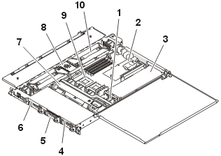
In Figure 3, the system cover and front bezel are removed to provide an interior
view of
the system.
Figure 3. Inside the System
|
| 1 |
Cooling fans (5 or 6) |
| 2 |
Optional ROMB card |
| 3 |
Riser-board expansion-card slots (2) |
| 4 |
Diskette drive |
| 5 |
Hard drives (3) |
| 6 |
CD drive |
| 7 |
SCSI backplane board |
| 8 |
Power supply distribution board |
| 9 |
Microprocessors (2) |
| 10 |
Power supplies (2) |
|
The system board can accommodate one or two microprocessors. A riser board
accommodates one or two PCI expansion cards. Up to four memory modules may be
installed on the system board.
The hard-drive bays provide space for up to three 1-inch SCSI hard drives or
two IDE hard drives. SCSI hard drives are connected to a SCSI host adapter on
the system board through the SCSI backplane board. IDE hard drives are
connected directly to the system board.
The peripheral bays provide space for an optional 3.5-inch diskette drive and
a CD drive.
The power supply distribution board (PSDB) provides hot-plug logic and power
distribution for the system. Two hot-pluggable, redundant power supplies provide
power to the system board and internal peripherals. Separate PSDBs, power
supplies, and power entry modules are provided for systems powered by -48 VDC
and for systems powered by AC input power.
During an installation or troubleshooting procedure, you may be required to
change a jumper. For information on the system board jumpers, see "Jumpers
and Connectors."
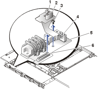
In Figure 4, the control panel is shown removed from the system chassis.
Figure 4.
Removing the Control Panel
|
| 1 |
Thumbscrew |
| 2 |
Fan power connector |
| 3 |
Hex-head Phillips screw |
| 4 |
System status indicator connector |
| 5 |
Control panel board |
| 6 |
Control panel flex cable connector |
|
To remove the control panel, perform the following steps.
 |
CAUTION: Read the safety instructions
in your System Information document. |
- Turn off the system, including any attached peripherals, and disconnect the
system from the electrical outlets.
- Open the system doors.
- Remove the front cooling fan, located behind
the control panel.
The fan power cable attaches to the control panel
flex cable assembly (see Figure 4).
- Loosen the thumbscrew that secures the flex cable assembly to the control panel board
(PLANAR).
- Remove the hex-head screw that secures the control panel board to the
chassis (see Figure 4).
- Slide back the control panel board and lift it from the system.
 |
CAUTION: Before
attempting to install the replacement power supply, check to ensure
that you are installing the same type power supply. You cannot install an AC
input power supply in a system configured for –48 VDC power; and
conversely, you cannot install a –48 VDC power supply in a system
configured for AC power. |
Your system may have one or two power supplies installed. If two power
supplies are installed, they are hot-pluggable, which means that you can replace one without
shutting down the system and turning off the power. For systems with two
hot-pluggable power supplies, begin this procedure at step 2.
 |
CAUTION: Read the safety instructions
in your System Information document. |
- If your system has a single power supply, turn off the system, including any attached peripherals, and disconnect the
system from the electrical outlets.
- Open the system doors.
 |
CAUTION: In a
system with two power supplies, the
power supplies are hot-pluggable. Remove and replace only one power
supply at a time. |
 |
CAUTION: The
connectors on the PSDB contain high voltages. Do not remove the metal
cover from the PSDB or touch the connectors on the PSDB or the power supply. |
- Identify the failed supply using the red fault indicator on the
top of the supply (see "Messages, Codes, and
Indicators").
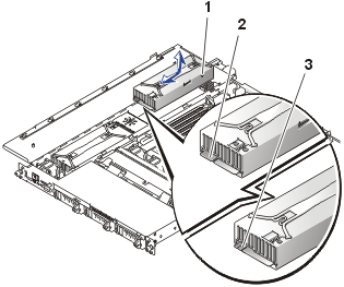
- While grasping the power supply handle, slide the power supply
away from the PSDB 0.75 inch (2 cm), and then lift the power supply out of
the chassis (see Figure 5).
Figure 5. Replacing a Power Supply
 |
| 1 |
Alignment stud |
| 2 |
AC power supply (one notch on card-edge
connector) |
| 3 |
–48 VDC power supply (two notches on
card-edge connector) |
|
- To install the replacement power supply, align the stud on the
side of the power supply (see Figure 5)
with the corresponding notch in the chassis, and then lower the power supply
into the chassis.
- Slide the power supply toward the PSDB until the power supply
connector is fully seated in the PSDB connector.
Your system may have five or six cooling fans. If your system has the
optional second power supply installed, the sixth fan is provided to cool the second power supply.
 |
CAUTION: Read the safety instructions
in your System Information document. |
- Open
the system doors.
 |
CAUTION: The
cooling fans are hot-pluggable. To maintain proper cooling while the
system is on, replace only one fan at a time. |
- Locate the faulty fan.
The amber fault indicator adjacent to the fan power connector
blinks if the fan is faulty.
- Check the cooling fan power cable connection on the system board
or control panel board (see Figure 6).
Figure 6. Cooling Fan
 |
| 1 |
Finger guard |
| 2 |
Optional power-supply cooling fan |
| 3 |
System board cooling fans (4) |
| 4 |
Control panel board |
| 5 |
Power-supply cooling fan |
|
- If the problem is not resolved, install a replacement cooling
fan.
- Disconnect the fan power cable from the system board or
control panel board.
- Lift the defective fan straight up out of the power-supply
bay or fan bracket (see Figure 6).
- Insert the new fan into the power-supply bay or fan bracket.
When replacing the fan, ensure that the finger
guard on the fan faces the back of the system and the fan cable points toward
the fan power cable connector on the system board or control panel board
(see Figure 6).
- Connect the fan power cable to the system board or control
panel board.
- If the replacement fan does not operate, the system board is faulty.
 |
NOTE: After
installing a new fan, allow up to 30 seconds for the system to recognize
the fan and determine whether it is working properly. |
 |
CAUTION: Read the safety instructions
in your System Information document. |
 |
CAUTION: The
cooling fan bracket must be replaced only with the power turned off. |
- Turn off the system, including any attached peripherals, and disconnect the
system from the electrical outlets.
- Open the system doors.
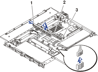
- Locate the cooling fan bracket (see Figure 7).
Figure 7. Removing the Cooling
Fan Bracket
 |
| 1 |
Release tab |
| 2 |
Cooling fan bracket |
| 3 |
System board cooling fan connectors (4) |
|
- Remove the cooling fan bracket:
- Disconnect the fan power cable from the system board for each cooling
fan mounted on the fan bracket.
Do not remove the fans from the bracket at this time.
- Press the fan bracket release tab, lift the fan bracket out of
the system with the fans attached, and set the bracket with fans
installed on a smooth surface.
- Lift the fans straight up out of the fan bracket (see Figure 7).
- Insert the fans into the new replacement fan bracket.
When replacing the fans, ensure that the finger
guard on the fan faces the back of the system and the fan cable points toward
the fan power cable connector on the system board (see Figure 7).
- Lower the fan bracket into place into the chassis.
The bracket release latch clicks as it locks in place.
- Connect the fan power cables to the system board.
 |
CAUTION: Read the safety instructions
in your System Information document. |
Your system may have a diskette drive, a CD drive, and up to three SCSI or up
to two IDE hard drives installed. Procedures for replacing all drives are found in the following subsections.
To remove the diskette drive, perform the following steps:
- Turn off the system, including any attached peripherals, and disconnect the
system from the electrical outlets.
- Open the system doors.
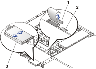
- Disconnect the diskette drive interface cable from the FLOPPY connector on the
top of the SCSI backplane assembly (or, if IDE drives are installed, from
the FLOPPY connector on the system board).
- Push down on the drive retention latch approximately 6.35 mm (0.25 inch) while
pulling the
diskette drive out of the peripheral bay (see Figure
8).
Figure 8. Replacing the Diskette Drive
 |
| 1 |
FLOPPY connector on SCSI backplane |
| 2 |
Diskette drive retention latch |
| 3 |
Diskette drive in peripheral bay |
|
Installing a Replacement Diskette Drive
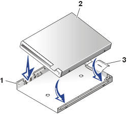
- If the replacement diskette drive has no carrier tray, remove the faulty
diskette drive from its carrier tray:
- Grasp both the right- and left-sides of the carrier tray and
gently bend the sides backward (see Figure
9) until the diskette drive is released from the carrier tray.
- Fit the right edge of the new replacement diskette drive into the
carrier tray, and then
lower the left edge of the drive into the carrier tray until the drive snaps
into place.
Figure 9. Removing the
Diskette Drive From the Carrier Tray
 |
| 1 |
Diskette drive carrier tray |
| 2 |
Diskette drive |
| 3 |
Retention tab |
|
|
|
|
|
- Attach the ribbon cable to the back of the diskette drive and
route the cable through the cable cover on the back of the carrier.
- Slide the drive and its carrier tray into the peripheral bay (see Figure
8)
until it is fully seated.
Ensure that you do not damage the ribbon cable at the back of
the drive.
The retention tab clicks when it locks in place.
- Connect the drive data cable to the connector labeled
"FLOPPY" on the SCSI backplane (or system board, if your system
has IDE hard drives installed).
- Close the system doors.
- Replace the front bezel, if it was removed.
- Reconnect the system and peripherals to their electrical
outlets.
Removing the CD Drive
To remove the CD drive, perform the following steps:
- Turn off the system, including any attached peripherals, and disconnect the
system from the electrical outlets.
- Open the system doors.
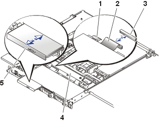
- Disconnect the CD drive interface cable from the connector on the
interposer board on the back of the CD drive assembly.
- Push down on the drive release latch approximately 6.35 mm (0.25 inch) while
pulling the
CD drive out of the peripheral bay (see Figure
10).
Figure 10. Replacing the CD Drive
 |
| 1 |
CD drive retention latch |
| 2 |
CD drive interface cable |
| 3 |
CD drive connector on SCSI
backplane |
| 4 |
SCSI backplane board |
| 5 |
CD drive in peripheral bay |
|
Installing a Replacement CD Drive
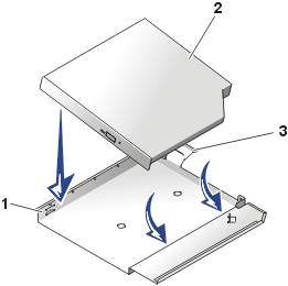
- If the replacement CD drive has no carrier tray, remove the faulty
CD drive from its carrier tray:
- Grasp both the right- and left-sides of the carrier tray and
gently bend the sides backward (see Figure
11) until the CD drive is released from the carrier tray.
- Fit the right edge of the new replacement CD drive into the
carrier tray, and then
lower the left edge of the drive into the carrier tray until the drive snaps
into place.
Figure 11. Removing the
CD Drive From its Carrier Tray
 |
| 1 |
CD drive carrier tray |
| 2 |
CD drive |
| 3 |
Retention tab |
|
|
|
|
|
- Slide the drive and its carrier tray into the peripheral bay (see Figure
10)
until it is fully seated.
The retention tab clicks when it locks in place.
- Connect the CD drive data cable to the connector on the
interposer board on the back of the CD drive assembly.
- Close the system doors.
- Replace the optional front bezel, if it was
removed.
- Reconnect the system and peripherals to their electrical
outlets.
Each SCSI hard drive is mounted in a hard-drive carrier.
 |
NOTICE: Hot-pluggable
hard drives are only supported if the
optional ROMB card and appropriate software is installed. |
 |
CAUTION: Read the safety instructions
in your System Information document. |
If a ROMB card and software are installed, hot-pluggable drives can be individually shut down and replaced while the system is operating.
To remove a hard drive and its carrier, perform the following steps:
- If the system does not have an optional ROMB card installed, shut down the system and disconnect the
peripheral and power cables from their outlets.
- Open the system doors.
- For systems with a ROMB card and software, shut down the hard-drive slot you intend to
remove.
Wait until both SCSI hard-drive indicators on the drive carrier handle are turned off
before proceeding.
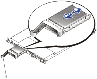
- Open the
drive carrier handle and slide the carrier forward until it is free of the drive bay
(see Figure 12).
Figure 12. Replacing the SCSI
Hard Drive and Carrier
 |
| 1 |
Hard-drive carrier handle |
|
To install a replacement hard drive, perform the following steps:
- If your replacement hard drive is installed in its carrier, go to step 4.
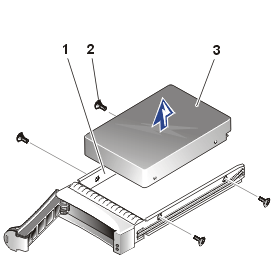
- If the replacement hard drive has no carrier, remove the faulty hard drive from its carrier:
- Remove
the four screws that secure the drive to the carrier (see Figure
13).
- Remove the hard drive from the carrier.
Figure 13. Removing the SCSI Hard Drive From the Carrier
 |
| 1 |
Hard-drive carrier |
| 2 |
Screws (4) |
| 3 |
Hard drive |
|
- Insert the replacement hard drive into the carrier
and install four screws to secure the drive.
- Open the handle on the carrier and install the replacement hard drive and carrier
into its slot in the drive bay (see Figure
12).
- Close the handle until it engages the front panel, locking the drive in place.
- Replace the front bezel, if it was removed.
- If the drive is a hot-pluggable replacement that has
already been prepared, turn on the drive bay and reintegrate the drive.
If the replacement drive is not a hot-pluggable hard drive, reconnect the system and peripherals to their electrical
outlets, turn on the system, and run the
system diagnostics
to test and prepare the new drive.
Your system may have one or two IDE hard drives.
Each IDE hard drive is mounted in a hard-drive carrier.
 |
NOTICE: IDE hard drives are
not supported in systems with a SCSI backplane board. |
 |
CAUTION: Read the safety instructions
in your System Information document. |
To remove an IDE hard drive and its carrier, perform the following steps:
- Turn off the system, including any attached peripherals, and disconnect the
system from the electrical outlets.
- Remove the optional front bezel, if it is installed.
- Open the system doors.
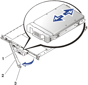
- Turn the compression latch that secures the drive-retention bracket to the chassis
(see Figure 14).
Figure 14. Removing the IDE
Drive and Carrier
 |
| 1 |
IDE hard drive and carrier |
| 2 |
IDE drive-retention bracket |
| 3 |
Compression latch |
|
- Rotate the right end of the drive-retention bracket away from
the system's front panel (see Figure 14).
- Set the drive retention bracket aside, out of the way. It must be installed after
the replacement drive is installed.
- Slide the IDE hard-drive carrier forward slightly (see Figure
14).
- Disconnect the IDE data cable from the back of the drive.
This cable connects to the other IDE drive (if present) and to the IDE connector on the
system board (see Figure 26).
- Disconnect the power cable from its connector on the back of the IDE hard
drive.
- Pull the IDE hard drive and its carrier out of its slot.
Installing a Replacement IDE Hard Drive
- If your replacement IDE hard drive is installed in its carrier, go to step
4.
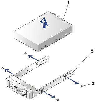
- If the replacement hard drive has no carrier, remove the faulty hard drive from its carrier:
- Remove
the four screws that secure the drive to the carrier (see Figure
15).
- Remove the hard drive from the carrier.
Figure 15. Removing the IDE Hard Drive From the Carrier
 |
| 1 |
IDE hard drive |
| 2 |
Hard-drive carrier |
| 3 |
Screws (4) |
|
- Insert the replacement hard drive into the carrier
and install four screws to secure the drive.
- Slide the replacement hard drive and carrier
into its slot in the drive bay (see Figure
14).
- Connect the IDE data cable to the drive (see Figure 26
for the location).
- Connect the IDE power Y-cable to the drive and to the IDE_POWER
connector on the system board (see Figure 26).
 |
CAUTION:
Failure to reinstall the retention bracket could cause damage to the IDE
hard drives. |
- Reinstall the IDE drive retention bracket and turn the compression latch
to secure it.
- Close the system doors.
- Replace the front bezel if one was removed.
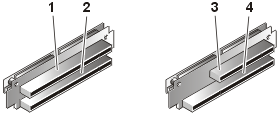
Expansion cards are installed on the system's riser board (see Figure 16).
The riser board plugs into the RISER connector on the system board
and is considered an extension of the system board.
Your system is available with two different riser board configurations (see Figure 16):
- Two 64-bit, 66-MHz expansion slots
- One 64-bit, 66-MHz expansion slot (PCI2) and one 32-bit, 33-MHz expansion
slot (PCI1) for 5-V cards
 |
NOTE: The
optional server management card uses the 32-bit, 33-MHz, 5-V expansion slot. |
You can install only half-length PCI cards in the lower expansion slot
(PCI2). You can install a full-length expansion card in the upper expansion slot
(PCI1) unless you have installed an optional server management card. In this
case, neither slot will accommodate full-length cards.
Figure 16. Riser-Board Expansion-Card
Connectors
 |
| 1 |
PCI1 (64-bit, 66-MHz) |
| 2 |
PCI2 (64-bit, 66-MHz) |
| 3 |
PCI1 (32-bit, 33-MHz) |
| 4 |
PCI2 (64-bit, 66-MHz) |
|
Figure 17. Replacing an Expansion Card
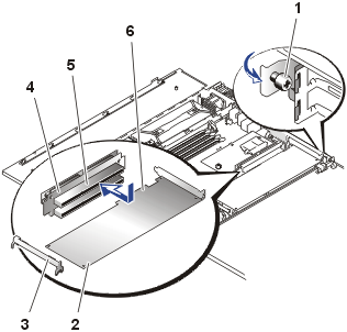 |
| 1 |
Captive thumbscrew on expansion-card latch |
| 2 |
Expansion card |
| 3 |
Full-length card guide |
| 4 |
Riser board |
| 5 |
Expansion-card connector |
| 6 |
Card-edge connector |
|
To replace an expansion card, perform the following steps.
 |
CAUTION: Read the safety instructions
in your System Information document. |
- Turn off the system, including any attached peripherals, and disconnect the system from
its electrical outlet.
- Open the system doors.
- Disconnect any cables connected to the card.
- Remove the expansion-card latch by loosening the captive thumbscrew and
removing the latch (see Figure 17).
- Grasp the expansion card by its edges and remove it from the expansion-card connector.
Installing a Replacement Expansion Card
To install a replacement or an additional expansion card, perform the following
steps:
- Prepare the replacement expansion card for installation.
See the documentation that came with the expansion card for information on configuring the
card, making internal connections, or otherwise customizing the card for the system.
- If the replacement card is an identical replacement, ensure that any
jumpers or configuration switches are set in an identical manner as the
expansion card you just removed.
- Locate the slot from which you removed the faulty expansion card.
If this is an additional expansion card, select the expansion slot in which
you will install the new expansion card.
- Install the new expansion card:
- Remove the filler panel bracket from the expansion slot, if
this is a new installation.
- Lower the card into the system.
If the card is a full-length card, you may need to guide
the front edge of the card into the full-length card support bracket.
- Insert the card-edge connector firmly into the expansion-card connector
on the riser board until the card is fully
seated.
- When the card is seated in the connector, replace and secure
the expansion-card latch.
- Connect any cables that should be attached to the card.
See the documentation supplied with the card for information
about its cable connections.
- Close the system doors.
- Replace the front bezel, if one was removed.
- Close the system doors, reconnect the system and peripherals
to their electrical outlets, and turn them on.
The four memory module sockets on the system board can accommodate from 256 MB to 4 GB of registered SDRAM. The memory module sockets are arranged in pairs consisting of two banks (bank 1 and bank 2). These banks are located near the
back edge of the system board (see Figure 26)
next to the back power supply.
 |
CAUTION: Read the safety instructions
in your System Information document. |
System Memory Upgrade Kits
The system is upgradable to 4 GB by installing combinations of 128-, 256-,
512-MB, and 1-GB registered memory modules. If you receive an error message
stating that the maximum memory has been exceeded, see “Messages,
Codes
and Indicators.” You can purchase memory upgrade kits from the system
manufacturer as needed.
 |
NOTE: The memory modules must be
PC-133 compliant. |
Memory Module Installation Guidelines
Starting with the socket farthest from the power-supply bay, the memory module sockets are labeled
BANK1_DIMM_A, BANK1_DIMM_B, BANK2_DIMMA, and BANK2_DIMM_B (see Figure
18). When you install
memory modules, follow these guidelines:
- You must install memory modules in matched pairs (see Figure
18).
- Install a pair of memory modules in bank 1 before installing a second pair
in bank 2.
Figure 18. Memory Module Slots
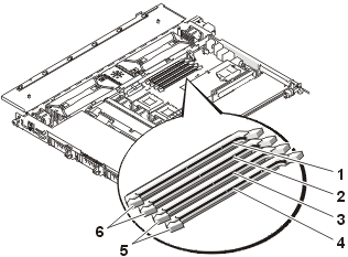 |
| 1 |
BANK2_DIMM_B |
| 2 |
BANK2_DIMM_A |
| 3 |
BANK1_DIMM_B |
| 4 |
BANK1_DIMM_A |
| 5 |
Bank 1 |
| 6 |
Bank 2 |
|
Table 2 illustrates several sample memory configurations based on
these guidelines.
Table 2. Sample Memory Module Configurations
Total Desired
Memory |
BANK 1
DIMM_A |
BANK 1
DIMM_B |
BANK 2
DIMM_A |
BANK 2
DIMM_B |
| 256 MB |
128 MB |
128 MB |
None |
None |
| 512 MB |
256 MB |
256 MB |
None |
None |
| 1 GB |
256 MB |
256 MB |
256 MB |
256 MB |
| 4 GB |
1 GB |
1 GB |
1 GB |
1 GB |
To perform a memory upgrade to the system board, perform the following steps.
 |
CAUTION: Before
you perform this procedure, you must turn off the system and disconnect
it from its power source. For more information, read the safety instructions
in your System Information document." |
- Open the system doors.
- Locate the memory module sockets in which you will install or
replace memory modules.
Figure 24 shows the general
location of the memory module sockets on the system board. Figure 16
shows the order of the memory module sockets.
- Install or replace the memory modules as necessary to reach the
desired memory total (see "Adding
or Installing Memory Modules" or "Removing
Memory Modules").
- Close the system doors, reconnect the system to the electrical
outlet, and turn on the system.
After the system completes the POST routine, it runs a memory test. The
system detects that the new memory does not match the system configuration
information and displays an error message.
- Press <F2> to enter the System Setup program, and check
the System Memory setting on the System Setup screens.
The system should have already changed the value in the System Memory
setting to reflect the newly installed memory.
- If the System Memory value is incorrect, one or more of
the memory modules may not be installed properly. Repeat steps 1 through 5,
checking to make sure that the memory modules are firmly seated in their
sockets.
- Run the system memory test in the system diagnostics.
To add or install a memory module, perform the following steps.
 |
CAUTION: Read the safety instructions
in your System Information document. |
- Press down and outward on the ejectors on the memory module socket, as
shown in Figure 19, to allow the memory
module to be inserted into the socket.
- Align the memory module's edge connector with the slot in the
center of the memory module socket, and insert the memory module into the
socket (see Figure 19).
The memory module socket has two alignment keys that allow the memory module
to be installed in the socket in only one way.
- Press down on the memory module with your thumbs while pulling
up on the ejectors with your index fingers to lock the memory module into
the socket (see Figure 19).
When the memory module is properly seated in the socket, the ejectors on the
memory module socket should align with the ejectors on the other sockets
with memory modules installed.
- Repeat steps 1 through 3 of this procedure to install the
remaining memory modules.
- Perform steps 4 through 7 of "Performing
a Memory Upgrade."
Figure 19. Adding or Installing a Memory Module
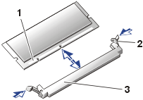 |
| 1 |
Edge connector alignment key |
| 2 |
Memory module socket ejectors (2) |
| 3 |
Socket |
|
 |
CAUTION: Read the safety instructions
in your System Information document. |
To remove a memory module, press down and outward on the ejectors on each end of the socket
until the memory module pops out of the socket (see Figure
20).
Figure 20. Removing Memory Modules
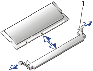 |
| 1 |
Memory module socket ejectors (2) |
|
The system board has two zero-insertion-force (ZIF) sockets which hold microprocessors
and heat-sink assemblies.
If you are adding a microprocessor, the
secondary microprocessor must have the same operating frequency as the first. For example,
if the system has a 1.13-GHz primary microprocessor, your secondary microprocessor must
also be a 1.13-GHz microprocessor.
 |
NOTICE: If you are upgrading a system by installing
a secondary microprocessor, or one or two higher-speed microprocessors, you must order
your upgrade kits from the system manufacturer. The upgrade kits from the system
manufacturer contain the correct version of the microprocessor for use as a secondary
microprocessor. |
To remove the microprocessor and heat-sink assembly, perform the following steps.
 |
CAUTION: Read the safety instructions in System Information document. |
 |
CAUTION: The
microprocessor chip and heat sink can become extremely hot. Be
sure the microprocessor has had sufficient time to cool before handling. |
 |
CAUTION: When
handling the microprocessor and heat-sink assembly, take care to avoid sharp edges on the
heat sink. |
- Turn off the system, including any attached peripherals, and disconnect the
power cable from its power source.
- Open the system doors.
- Locate the microprocessor ZIF sockets into which you will install or replace a
microprocessor and heat-sink assembly.
- To remove the retention clip that secures the heat sink to the
microprocessor socket, press down firmly on the tab on the retention clip,
and then remove the clip from the heat sink (see Figure
21).
- Remove the heat sink and set it down with the underside of the heat sink
facing up.
 |
NOTICE: Note the orientation of the heat sink with respect to the
microprocessor and its ZIF socket. The heat sink and its securing clip must be
aligned with the arrow beside the ZIF socket on the system board. |
 |
NOTICE: Never
remove the heat sink from a microprocessor unless you intend to remove the
microprocessor. The heat sink is necessary to maintain proper heat transfer
from the microprocessor. |
- Pull the socket release lever straight up until the microprocessor is
released (see Figure 22).
Figure 21. Retention Clip and Heat Sink Removal
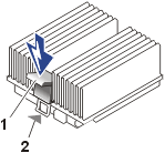 |
| 1 |
Retention clip |
| 2 |
Alignment arrow |
|
- Lift the microprocessor straight up and away from the ZIF socket (see Figure
22).
Leave the release
lever in the upright position so that the socket is ready for the
replacement microprocessor.
Figure 22. Removing the Microprocessor
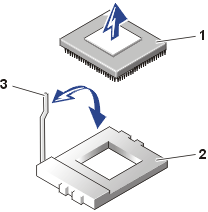 |
| 1 |
Microprocessor chip |
| 2 |
ZIF socket |
| 3 |
Release lever |
|
 |
CAUTION: Read the safety instructions
in your System Information document. |
 |
NOTICE: Be
careful not to bend any of the pins when unpacking the microprocessor
chip. Bending the pins can permanently damage the microprocessor chip. |
To install an additional or a replacement microprocessor and heat-sink assembly,
perform the following steps.
This procedure assumes the system cover and front bezel have been removed, the
system power is off, and all power cables and peripheral cables are disconnected.
- Unpack the new microprocessor.
If any of the pins on the microprocessor appear bent, see "Obtaining
Technical Assistance" for instructions on obtaining technical assistance.
 |
NOTICE: Identifying
the pin-1 corners is critical to positioning the chip correctly. |
- Identify the pin-1 corner of the microprocessor by turning the
chip over and locating the tiny gold triangle that extends from one corner
of the large central rectangular area. The gold triangle points toward pin 1,
which is also uniquely identified by a triangular pad (see Figure
23).
Figure 23. Pin 1 Identification
 |
| 1 |
Pin 1 corner (gold
triangle) |
|
- Align the pin-1 corner of the microprocessor chip (see Figure 24)
with the pin-1 corner of the microprocessor socket.
 |
NOTICE: Positioning
the microprocessor incorrectly can permanently damage the chip and the
system when you turn on the system. |
- Install the microprocessor chip in the socket (see Figure 24).
- If the release lever on the microprocessor socket is not all
the way up, move it to that position now.
 |
NOTICE: When
placing the microprocessor chip in the socket, be sure that all of the
pins on the chip go into the corresponding holes of the socket. Be
careful not to bend the pins. |
- With the pin-1 corners of the chip and socket aligned, set the
chip lightly in the socket and make sure that all pins are matched with
the correct holes in the socket.
Because the system uses a ZIF microprocessor socket, there is no need
to use force (which could bend the pins if the chip is misaligned).
When the chip is positioned correctly, it should drop down into the socket
with minimal pressure.
- When the chip is fully seated in the socket, rotate the socket
release lever back down until it snaps into place, securing the chip.
Figure 24. Installing the Microprocessor
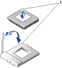 |
| 1 |
Pin 1 corner of
microprocessor aligned with pin-1 corner of ZIF socket |
|
 |
NOTICE: Note the orientation of the heat sink with respect to the
microprocessor and its ZIF socket. The heat sink and its securing clip must be
aligned with the arrow head beside the ZIF socket on the system board. |
- Place the new heat sink on top of the microprocessor chip (see Figure 25).
- Replace the retention clip:
- Orient the clip so that the release tab is facing the back
of the system and the alignment arrow on the system board.
- Hook the unfolded end of the clip over the tab on the edge
of the socket facing the front of the system.
- Press down on the release tab on the free end of the clip to
snap the clip over the tab on the socket (see Figure 25).
Figure 25. Installing the Heat Sink and
Retention Clip
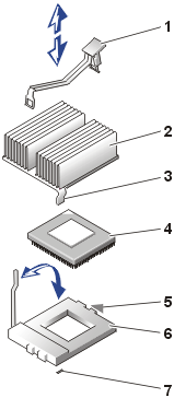 |
| 1 |
Retention clip |
| 2 |
Heat sink |
| 3 |
Alignment tab |
| 4 |
Microprocessor chip |
| 5 |
Alignment arrow head on system board |
| 6 |
ZIF socket |
| 7 |
Slot in system board |
|
- Close the system doors.
- Replace the front bezel, if one was removed.
- Reconnect your system and peripherals to their electrical outlets, and
turn them on.
As the system boots, it detects the presence of the new microprocessor and
automatically changes the system configuration information in the System
Setup program.
- Press <F2> to enter the System Setup program, and check that the
microprocessor categories match the new system configuration.
- Run the system diagnostics to verify that the new microprocessor is
operating correctly.
See "Running the System
Diagnostics" for information on running the diagnostics and
troubleshooting any problems that may occur.
Figure 26 identifies the system board features. Use this figure when replacing your system
board or components that attach to the system board.
Figure 26. System Board Features
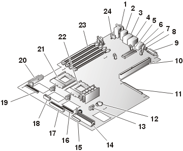 |
1 |
Serial (SERIAL [top]) and video (VGA [bottom]) ports |
2 |
Mouse (MOUSE [top]) and keyboard (KYBD
[bottom]) connectors |
3 |
NIC (ETHERNETn [top]) and USB (USB2
[bottom]) connectors |
4 |
NIC (ETHERNETn [top]) and USB (USB1 [bottom]) connectors |
5 |
ROMB card connector (RAID) |
6 |
Server management port connector |
7 |
Cable-management arm system status connector |
8 |
System ID button (REAR_ID) |
9 |
External SCSI connector (SCSI_B) |
| 10 |
Riser board connector (RISER) |
11 |
Embedded remote assistant connector (ERA) |
12 |
System battery (BATTERY) |
13 |
System board fan connectors (FANn) (4) |
14 |
SCSI backplane board connector (BACKPLANE_1) |
15 |
Diskette drive connector (FLOPPY) |
16 |
CD drive connector (CD-ROM) |
17 |
IDE drive connector (IDE) |
18 |
IDE drive power connector (IDE_POWER) |
| 19 |
Control panel connector (FRONT_ PANEL) |
| 20 |
System board power connector (POWER) |
| 21 |
Microprocessor 2 (PROCESSOR2) |
| 22 |
Microprocessor 1 (PROCESSOR1) |
| 23 |
Memory module sockets (BANK1_DIMM_A through
BANK2_DIMM_B) |
| 24 |
Optional power-supply fan connector (FAN_6) |
|
Figure 27. Replacing the System Board
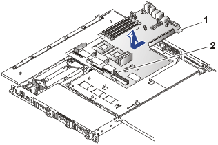 |
| 1 |
System board |
| 2 |
Thumbscrew |
|
Removing the System Board
To remove the system board, perform the following steps.
 |
CAUTION: Read the safety instructions
in your System Information document. |
- Turn off the system, including any attached peripherals, and disconnect the system from
its electrical outlet.
- Open the system doors.
- Remove the SCSI backplane, if it is
installed.
- Disconnect the fan power cables and remove
the fans and the fan bracket assembly on the system board.
- Disconnect the DC power connector on the system board (POWER).
- Disconnect the control panel connector on the system board (FRONT_PANEL).
- Remove all external peripheral cables from their connectors at the back of the system.
- Record the locations and remove all internal cables attached to
the system board.
- Remove the expansion cards.
- Loosen the thumbscrew securing the system board to the chassis.
- Slide the system board toward the front of the system chassis about 6.3 mm
(0.25 inch).
- Carefully lift the system board up and out of the chassis.
Be sure to lift evenly and not twist the system board.
- Place the system board on a smooth, antistatic surface.
- Remove the optional ROMB card, if it is installed.
- Remove the microprocessor and heat-sink
assemblies.
- Remove the memory modules.
Installing a Replacement System Board
To install a replacement system board, perform the following steps:
- Press the system board evenly onto all of the grounding tabs on the floor of
the chassis, and then slide it toward the back of the system about 6.3 mm (0.25 inch).
- Tighten the thumbscrew to secure the system board to the chassis.
- Install the memory modules.
- Install the microprocessor and heat-sink
assemblies.
- Check to ensure that the system board jumpers and switches are set to the same settings as
the board you removed.
- Install the expansion
cards.
- Connect all internal cables.
- Install the optional ROMB card, if one was
installed on the system board you removed.
- Replace
the cooling fans and their fan bracket assembly.
- Carefully check for any cables or components not installed or improperly
seated in their connectors on the system board.
- Close the system doors.
- Replace the front bezel, if one was removed.
- Connect external peripheral cables.
- Connect the power cable to the system and turn the system on.
 |
NOTICE: Systems
with IDE hard drives do not have a SCSI backplane board. |
The SCSI backplane board has connectors on the top that connect to the CD
drive and the diskette drive. The bottom of the SCSI backplane board has connectors for connecting
hard drives to the system board SCSI controller.
A release latch on the back-right corner must be moved to the left to release
the SCSI backplane board (it is not necessary to touch this latch when
installing the SCSI backplane board).
Figure 28. SCSI Backplane
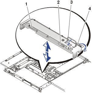 |
| 1 |
CD drive connector |
| 2 |
Diskette drive connector |
| 3 |
Handle |
| 4 |
Release latch |
|
To remove a SCSI backplane board, perform the following steps.
 |
CAUTION: Read the safety instructions
in your System Information document. |
- Turn off the system, including any attached peripherals, and disconnect the system from
its electrical outlet.
- Open the system doors.
- Remove the front fan bracket.
- Pull each hard-drive carrier partially out of its slot,
approximately 2.5 cm (1 inch).
- Disconnect the diskette drive interface cable from the top right of the SCSI backplane
board (see Figure 8).
- Disconnect the CD drive interface cable from the top left of the SCSI
backplane board (see Figure 10).
- Press the release latch toward the SCSI backplane board and lift the SCSI backplane board up
and out of the system chassis.
 |
CAUTION: Read the safety instructions
in your System Information document. |
To remove a power supply distribution board (PSDB), perform the following steps.
 |
CAUTION: Avoid
touching the cable connectors on the power supplies. Wait 10 to 20 seconds after
disconnecting the power cables before removing the power supplies or coming into contact
with their cable connectors. |
Figure 29. Power
Supply Distribution Board Removal (AC Version)
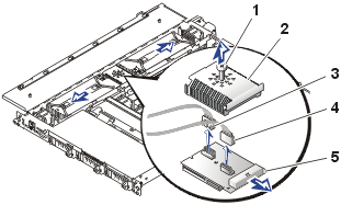 |
| 1 |
Screw |
| 2 |
Cover |
| 3 |
AC input cable connector |
| 4 |
AC input cable connector |
| 5 |
DC output power connector |
|
Figure 30. Power
Supply Distribution Board Removal (DC Version)
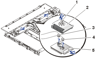 |
| 1 |
Screw |
| 2 |
Cover |
| 3 |
DC input cable connector |
| 4 |
DC input cable connector |
| 5 |
DC output power connector |
|
- Turn off the system, including any attached peripherals, and disconnect the system from its electrical outlet.
- Open the system doors.
- Remove both power supplies.
- Remove the screw securing the cover to the PSDB.
- Disconnect the DC power cable connected to the system board.
- Disconnect both of the input power cables connected to the top of the PSDB.
- Lift the PSDB out of the system chassis.
 |
CAUTION: Read the safety instructions in System Information document. |
Your system may have an AC power entry module, or it may have a –48 VDC power
entry module. The two power entry modules are shown in Figure
31.
Figure 31. Power
Entry Modules (AC module is shown installed)
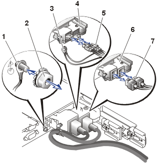 |
| 1 |
Ground stud (for DC
cables) |
| 2 |
Grounding nut (for DC cables) |
| 3 |
Ground lug (DC cables) |
| 4 |
–48 VDC power entry module |
| 5 |
–48 VDC power entry cable |
| 6 |
AC power entry module |
| 7 |
AC power cables |
|
This procedure may be used for AC power entry modules and –48 VDC power entry
modules.
Figure 32. Removing the Power Entry Module
(AC
module shown)
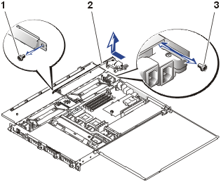 |
| 1 |
Screw |
| 2 |
Power entry module |
| 3 |
Screw |
|
- Turn off the system, including any attached peripherals, and disconnect the system from its electrical
outlet(s).
- Open the system doors.
- Remove the power cables from both power entry module connectors. If you
are removing –48 VDC power cables, you must also remove the ground lugs
from the ground stud beside the power entry module.
 |
CAUTION: Avoid
touching the cable connectors on the power supplies. Wait 10 to 20 seconds after
disconnecting the power cables before removing the power supplies or coming into contact
with their cable connectors. |
- Remove both power supplies.
- At the back of the chassis, remove the screw that secures the power entry
module to the chassis (see Figure 32).
- Remove the screw that secures the power supply distribution board cover (see
Figure 30).
- On the side of the chassis, remove the screw that secures the forward end of
the power entry module.
- Disconnect the two power cables from the top of the power supply
distribution board (see Figure 30).
- Pull the power cables out the hole in the side of the chassis and set the
power entry module aside.
Installing the Replacement Power Entry Module
 |
CAUTION: Before
attempting to install the replacement power entry module, check to ensure
that you are installing the same type module. You cannot install an AC
power entry module in a system configured for –48 VDC power; and
conversely, you cannot install a –48 VDC power entry module in a system
configured for AC power. |
- At the forward end of the power entry module, insert the two cable
connectors into the hole on the side of the chassis adjacent to the power
supply distribution board.
- Secure the forward end of the power entry module to the side of the
chassis with the screw you removed in step 7 of "Removing the
Power Entry Module" (see Figure 32).
- Secure the back of the power entry module to the system back panel with
the screw you removed in step 5 of "Removing the Power Entry
Module" (see Figure 32).
- Connect the two power input cables to the top of the power supply
distribution board (see Figure 30).
- Secure the top cover to the power supply distribution board (see Figure
30).
- Replace both power supplies.
- Close the system doors.
- Install the power input cables to the power entry module's receptacles. If
you are installing a –48 VDC cable assembly, install the ground lugs on
the ground stud on the back panel of the system and secure it with the
grounding nut (see Figure 31).
To replace the optional ROMB card, perform the following steps.
 |
CAUTION: Read the safety instructions in System Information document. |
Figure 33.
Replacing
the ROMB Card
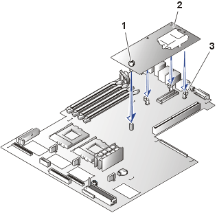 |
| 1 |
Thumbscrew |
| 2 |
ROMB card |
| 3 |
Plastic standoffs (3) |
|
- Turn off the system, including any attached peripherals, and disconnect the power
cable from its power source.
- Open the system doors.
- Locate the ROMB card on the system board.
- Loosen the thumbscrew securing the ROMB card to the system board.
- Move the three plastic standoffs away from the ROMB card and lift the ROMB card
off its connector.
- Locate the ROMB card connector on the system board (see Figure 33).
- Align the edges of the ROMB card with the three plastic
standoffs on the system board (see Figure 33)
and install the card.
When the card is fully seated, the three plastic standoffs snap over
the edge of the card.
- Secure the ROMB card with the thumbscrew (see Figure 33).
- Check that the ROMB back-up battery (see Figure 33)
is connected to the ROMB card.
- If necessary, connect the ROMB battery cable.
- Close the system doors.
- Replace the front bezel, if one was removed.
- Reconnect the system and peripherals to their power sources, and
turn them on.
- Enter the System Setup program and verify that the setting for
the SCSI controller has changed to properly reflect the presence of the RAID hardware
(see "Using the
System Setup Program").
- Reinstall the RAID software, if necessary (see the ROMB card software
documentation for more information).
To replace the optional ERA card, perform the following steps.
 |
CAUTION: Read the safety instructions in System Information document. |
Figure 34.
Replacing
the ERA Card
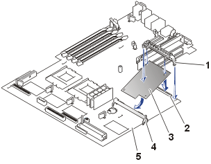 |
| 1 |
Retention clip |
| 2 |
ERA card connector |
| 3 |
ERA card |
| 4 |
Support bracket |
| 5 |
System board |
|
- Turn off the system, including any attached peripherals, and disconnect the power
cable from its power source.
- Open the system doors.
- Locate the ERA card on the system board.
- Loosen the plastic retention clip securing the ERA card to the system board.
- Lift the ERA card
off its connector and rotate the board up and out of its support bracket.
- Locate the ERA card connector on the system board (see Figure 34).
- Align the forward edges of the ERA card with the plastic support bracket on the system board (see Figure 34)
and lower the card into the ERA card connector on the system board.
- Secure the ERA card with the plastic retention clip (see Figure 34).
- Close the system doors.
- Replace the front bezel, if one was removed.
- Reconnect the system and peripherals to their power sources, and
turn them on.
The system battery is a 3.0-V, coin-cell battery that maintains system
configuration, date, and time information in a special section of memory when
you turn off the system. The operating life of the battery ranges from 2 to 5
years, depending on how you use the system (for example, if you keep the system
on most of the time, the battery gets little use and thus lasts longer). You may
need to replace the battery if an incorrect time or date is displayed during the
boot routine.
You can operate the system without a battery; however, the system
configuration information maintained by the battery in NVRAM is erased each time
you remove power from the system. Therefore, you must reenter the system
configuration information and reset the options each time the system boots until
you replace the battery.
To replace the battery, perform the following steps.
 |
CAUTION: Before
you perform this procedure, you must turn off the system and disconnect
it from its power source. See "Protecting Against Electrostatic
Discharge" in the safety instructions in your System Information
document. |
 |
CAUTION: There
is a danger of a new battery exploding if it is incorrectly installed.
Replace the battery only with the same or equivalent type recommended by
the manufacturer. Discard used batteries according to the manufacturer's
instructions. See the System Information document for additional
information. |
- Enter the System Setup program and, if possible, make a printed
copy of the System Setup screens (see "Using the
System Setup Program").
- Turn off the system, including any attached peripherals, and
disconnect the system from the electrical outlet.
- Open the system doors.
- Remove the system battery (see Figure 26
for its location).
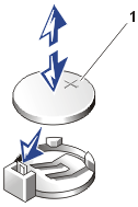
You can pry the system battery out of its socket with your
fingers or with a blunt, nonconductive object such as a plastic screwdriver.
- Install the new system battery with the side labeled
"+" facing up (see Figure 35).
Figure 35. Replacing
the System Battery
- Close the system doors.
- Replace the front bezel, if one was removed.
- Reconnect the system and any attached peripherals to their
electrical outlets, and turn them on.
- Enter the System Setup program to confirm that the battery is
operating properly (see "Using the System Setup
Program").
- Enter the correct time and date in the System Setup program's Time
and Date settings.
- Re-enter any system configuration information that is no longer
displayed on the System Setup screens, and then exit the System Setup
program.
- To test the newly installed battery, power down and disconnect
the system from its electrical source for at least an hour.
- After an hour, connect the system to its electrical source and
turn on the power.
- Enter the System Setup program and if the time and date are
still incorrect, obtain technical
assistance.
Back to Contents Page


