Back to Contents Page
System Overview
Dell™ PowerEdge™ 1800 Systems User's Guide
 System Orientation
Indicators on the Bezel
Front-Panel Features and Indicators
Back-Panel Features and Indicators
Power Indicator Codes
System Features
Supported Operating Systems
Power Protection Devices
Other Documents You May Need
Obtaining Technical Assistance
This section describes the major hardware and software features of your system and provides information about the indicators on the system's front and back panels. It also provides information about other documents you may need when you set up your system and how you can obtain technical assistance.
System Orientation
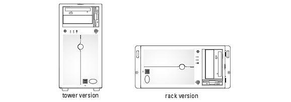
Figure 1-1 shows the rack and tower versions of your system. The illustrations in this document are based on the rack version.
Figure 1-1. Tower and Rack-Mount Orientations With Standard Bezel
Indicators on the Bezel
The system bezel (standard) incorporates blue and amber system-status indicators. The blue indicator lights up when the system is operating correctly. The amber indicator lights when the system needs attention due to a problem with power supplies, fans, system temperature, or SCSI hard drives.
Table 1-1 lists the system's indicator patterns. Different patterns are displayed that indicate events occurring in the system.
Table 1-1. System-Status Indicator Patterns
|
Blue Indicator
|
Amber Indicator
|
Description
|
Off
|
Off
|
Power is not available to the system.
|
Off
|
Blinking
|
The system has detected an error. See your Installation and Troubleshooting Guide for more information.
|
On
|
Off
|
Power is on, and the system is operational.
|
Blinking
|
Off
|
The indicator has been activated to identify the system in a rack.
|
|
NOTE: While the system is being identified, the blue indicator blinks, even though an error has been detected. After the system is identified, the blue indicator stops blinking and the amber indicator resumes blinking.
|
Front-Panel Features and Indicators
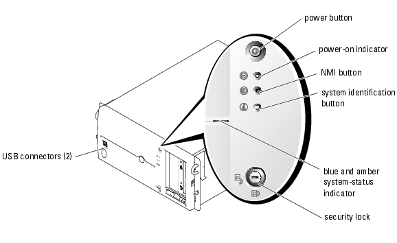
Figure 1-2 shows the controls, indicators, and connectors located on the system's front panel.
Figure 1-2. Front-Panel Features and Indicators
Table 1-2. Front-Panel LED Indicators, Buttons, and Connectors
|
Indicator, Button,
or Connector
|
Icon
|
Description
|
Blue system-status indicator
|
|
The blue system-status indicator lights during normal system operation. Both the systems management software and the identification buttons located on the front and back of the system can cause the blue system-status indicator to flash to identify a particular system.
|
Amber system-status indicator
|
|
The amber system-status indicator flashes when the system needs attention due to a problem with power supplies, fans, system temperature, or SCSI hard drives.
NOTE: If the system is connected to AC power and an error has been detected, the amber system status indicator flashes regardless of whether the system has been powered on.
|
Power button and power-button indicator
|

|
The power button controls the DC power supply output to the system.
NOTE: If you turn off the system using the power button and the system is running an ACPI-compliant operating system, the system performs a smooth shutdown before the power is turned off. If the system is not running an ACPI-compliant operating system, the power is turned off immediately after the power button is pressed.
The power-button indicator lights up when power is supplied to the system and the system is operational; it is off when no power is supplied to the system; and it is blinking when the system is in a standby state. For information on standby states, see your operating system documentation.
|
Power-on indicator
|

|
The power-on indicator lights when the system power is on. The power-on indicator blinks when power is available to the system but the system is not powered on.
|
System identification button
|

|
The identification buttons on the front and back panels can be used to locate a particular system within a rack. When one of these buttons is pressed, the blue system status indicator on the front and back blinks until one of the buttons is pressed again.
|
USB connectors
|

|
Connects USB 2.0-compliant devices to the system.
|
NMI button
|

|
Used to troubleshoot software and device driver errors when using certain operating systems. This button can be pressed using the end of a paper clip.
Use this button only if directed to do so by qualified support personnel or by the operating system's documentation.
|
SCSI Hard-Drive Indicator Codes
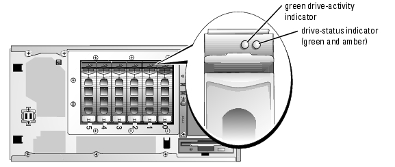
Each SCSI hard-drive carrier has two indicators: an activity indicator and a status indicator (see Figure 1-3). The indicators provide information on the status of the hard drive.

|
NOTE: The drive-activity indicator is not available on systems with optional SATA hard-drives. |
Figure 1-3. SCSI Hard-Drive Indicators
Table 1-3 lists the drive indicator codes. Different codes are displayed as drive events occur in the system. For example, if a hard-drive fails, the "drive failed" code appears. After the drive is selected for removal, the "drive being prepared for removal" code appears, followed by the "drive ready for insertion or removal" code. After the replacement drive is installed, the "drive being prepared for operation" code appears, followed by the "drive online" code.
|
|
NOTE: If RAID is not activated, only the "drive online" indicator pattern appears. The drive-activity indicator also blinks when the drive is being accessed. |
Table 1-3. SCSI Hard-Drive Status Indicator Codes
|
Drive-Status Indicator
|
Indicator Code
|
|---|
Drive bay empty
| Off
|
Drive being prepared for operation, drive online
| Steady green
|
Drive being identified or prepared for removal
| Blinks green three times per second at equal intervals
|
Drive rebuilding
| Blinks green once per second
|
Drive offline or failed
| Steady amber
|
Back-Panel Features and Indicators
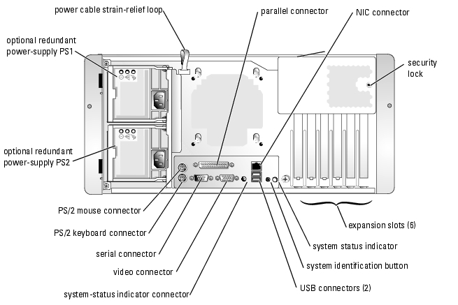
Figure 1-4 shows the controls, indicators, and connectors located on the system's back panel.
Figure 1-4. Back-Panel Features
Connecting External Devices
When connecting external devices to your system, follow these guidelines:
- Most devices must be connected to a specific connector and device drivers must be installed before the device operates properly. (Device drivers are normally included with your operating system software or with the device itself.) See the documentation that accompanied the device for specific installation and configuration instructions.
- Always attach external devices while your system is turned off. Next, turn on any external devices before you turn on the system (unless the documentation for the device specifies otherwise).
For information about individual connectors, see your Installation and Troubleshooting Guide. For information about enabling, disabling, and configuring I/O ports and connectors, see "Using the System Setup Program."
Power Indicator Codes
The power button on the front panel controls the power input to the system's power supplies. The power indicator can provide information on power status (see Figure 1-2). Table 1-4 lists the power button indicator codes.
Table 1-4. Power Button Indicators
|
Indicator
|
Function
|
On
|
Indicates that power is supplied to the system and that the system is operational.
|
Off
|
Indicates that no power is supplied to the system.
|
Blinking
|
Indicates that power is supplied to the system but the system is in a standby state. For information on standby states, see your operating system documentation.
|
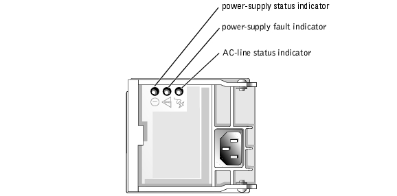
The indicators on the optional redundant power supplies show whether power is present or whether a power fault has occurred (see Figure 1-5).
Table 1-5. Redundant Power-Supply Indicators
|
Indicator
|
Function
|
Power supply status
|
Green indicates that the power supply is operational.
|
Power supply fault
|
Amber indicates a problem with the power supply.
|
AC line status
|
Green indicates that a valid AC source is connected to the power supply.
|
Figure 1-5. Redundant Power-Supply Indicators
System Features
- One or two Intel® Xeon™ processors with an internal operating speed of at least 2.8 GHz, internal cache of at least 1 MB, and a front-side bus operating at 800 MHz
|
|
NOTE: If you decide to upgrade your system by installing a second processor, you must order the processor upgrade kits from Dell. Not all versions of the Intel Xeon processor work properly as additional processors. The upgrade kit from Dell contains the correct version of the processor, heat sink, and fan as well as the instructions for performing the upgrade. Both processors must have the same internal operating frequency and cache size. |
- A minimum of 256 MB of registered PC2-3200 DDR 2 400 SDRAM memory modules, upgradable to a maximum of 12 GB (if supported by your operating system) by installing the memory modules on the system board
|
|
NOTE: Two-way interleaving is not supported in the 256-MB single memory module configuration. |
|
|
NOTE: The chip fail feature is only supported using x4 memory modules. |
- Support for up to six 1-inch, cabled, internal SATA hard drives
- Support for up to six 1-inch, optional internal hot-pluggable (with optional RAID controller card) U320 hard drives
- Support for a half-height optional tape back-up unit in the peripheral bay
- An optional single, 1.44-MB, 3.5-inch diskette drive
- An optional IDE CD, DVD, or combination CD-RW/DVD drive
|
|
NOTE: DVD devices are data only. |
- Up to two optional hot-pluggable, 675-W power supplies in a 1 + 1 redundant configuration, or one 650-W non-redundant power supply
- Two system cooling fans
The system board includes the following features:
- Six PCI slots located on the system board that support a combination of PCI, PCI Express, and PCI-X slots.
- Six PCI slots located on the system board. PCI slot 1 is a 64-bit, 66-MHz PCI (3.3 V) slot; PCI slot 2 is a PCI Express x4 (3.3 V) slot; PCI slot 3 is a PCI Express x8 (3.3 V) slot; PCI slot 4 is a 32-bit, 33-MHz PCI (5 V) slot; and PCI slots 5 and 6 are 64-bit, 100-MHz PCI-X (3.3 V) slots.
|
|
NOTE: Slot 1 accepts half-length PCI cards. Slot 6 accepts full-length unless SCSI is used (because of the SCSI cabling). All other slots accept full-length PCI cards. |
- Two integrated SATA connectors and an integrated SATA controller. Each SATA connector supports one non–hot-plug SATA hard drive. Up to six SATA hard drives can be installed and controlled by an optional SATA controller card.
- An integrated, single-channel U320 SCSI controller. The internal channel supports up to six SCSI hard drives using the 1x6 SCSI backplane. The SCSI backplane automatically configures SCSI ID numbers and SCSI termination, greatly simplifying drive installation.
- An integrated Gigabit Ethernet NIC, capable of supporting 10-Mbps, 100-Mbps, and 1000-Mbps data rates.
- Four USB 2.0-compliant connectors (two on the front and two on the back) capable of supporting a diskette drive, CD drive, keyboard, mouse, or USB flash drive.
- An integrated VGA-compatible video subsystem with an ATI Radeon 7000-M video controller. This video subsystem contains 16 MB of SDRAM video memory (nonupgradable). Maximum resolution is 1600 x 1200 with 64,000 colors; true-color graphics are supported in the following resolutions: 640 x 480, 800 x 600, 1024 x 768, 1152 x 864, and 1280 x 1024.
- IPMI1.5-compatible systems management circuitry that monitors operation of the system fans as well as critical system voltages and temperatures. The systems management circuitry works in conjunction with the systems management software.
- Back-panel connectors include mouse, keyboard, serial, video, parallel, two USB connectors, and a NIC connector.
- Front-panel connectors include two USB connectors.
- System ID button on the front and back panels.
- An intrusion switch that signals the appropriate systems management software if the cover is opened.
For more information about specific features, see "Technical Specifications."
The following software is included with your system:
- A System Setup program for quickly viewing and changing system configuration information. For more information on this program, see "Using the System Setup Program."
- Enhanced security features, including a system password and a setup password, available through the System Setup program.
- System diagnostics for evaluating system components and devices. For information about using the system diagnostics, see "Running the System Diagnostics" in your Installation and Troubleshooting Guide.
- Video drivers for displaying many popular applications in high-resolution modes.
- SATA or SCSI device drivers that allow the operating system to communicate with devices attached to the integrated SATA or SCSI subsystem. For more information about these drivers, see "Installing Drives" in your Installation and Troubleshooting Guide.
Supported Operating Systems
- Microsoft® Windows® 2000 Server and Advanced Server
- Microsoft Windows Server 2003 Standard Edition, Enterprise Edition, Small Business Premium Edition, and Small Business Standard Edition
- Red Hat® Linux Enterprise Server AS and ES (version 3)
- Red Hat Linux Enterprise Server AS and ES (version 2.1)
- Novell® NetWare® 6.5 and 5.1
Power Protection Devices
Certain devices protect your system from the effects of problems such as power surges and power failures.
- PDU — Uses circuit breakers to ensure that the AC current load does not exceed the PDU's rating.
- Surge protector — Prevents voltage spikes, such as those that may occur during an electrical storm, from entering the system through the electrical outlet. They do not protect against brownouts, which occur when the voltage drops more than 20 percent below the normal AC line voltage level.
- Line conditioner — Maintains a system's AC power source voltage at a moderately constant level and provides protection from brownouts, but does not protect against a complete power loss.
- UPS — Uses battery power to keep the system running when AC power is unavailable. The battery is charged by AC power while it is available so that after AC power is lost, the battery can provide power to the system for a limited amount of time—from 5 minutes to approximately an hour. A UPS that provides only 5 minutes of battery power allows you to save your files and to shut down the system. Use surge protectors and PDUs with all universal power supplies, and ensure that the UPS is UL-safety approved.
Other Documents You May Need

|
CAUTION: The Product Information Guide provides important safety and regulatory information. Warranty information may be included within this document or as a separate document. |
- The Rack Installation Guide or Rack Installation Instructions included with your rack solution describes how to install your system into a rack.
- The Getting Started Guide shows how to initially set up your system.
- The Installation and Troubleshooting Guide describes how to troubleshoot the system and install or replace system components.
- Systems management software documentation describes the features, requirements, installation, and basic operation of the software.
- Baseboard management controller (BMC) documentation describes the features and configuration options of the BMC.
- Operating system documentation describes how to install (if necessary), configure, and use the operating system software.
- Documentation for any components you purchased separately provides information to configure and install these options.
- Updates are sometimes included with the system to describe changes to the system, software, and/or documentation.
|
|
NOTE: Always read the updates first because they often supersede information in other documents. |
- Release notes or readme files may be included to provide either last-minute updates to the system or documentation, or to provide advanced technical-reference material intended for experienced users or technicians.
Obtaining Technical Assistance
If you do not understand a procedure in this guide or if the system does not perform as expected, see your Installation and Troubleshooting Guide.
Dell Enterprise Training and Certification is available; go to www.dell.com/training for more information. This service may not be offered in all locations.
Back to Contents Page