 Jumpers—A General Explanation
Dell™ PowerEdge™ 1850 Systems Installation and Troubleshooting Guide
Disabling a Forgotten Password
This section provides specific information about the system jumpers. It also provides some basic information on jumpers and switches and describes the connectors on the various boards in the system.
Jumpers provide a convenient and reversible way of reconfiguring the circuitry on a printed circuit board. When reconfiguring the system, you may need to change jumper settings on circuit boards or drives.
Jumpers are small blocks on a circuit board with two or more pins emerging from them. Plastic plugs containing a wire fit down over the pins. The wire connects the pins and creates a circuit. To change a jumper setting, pull the plug off its pin(s) and carefully fit it down onto the pin(s) indicated. Figure A-1 shows an example of a jumper.
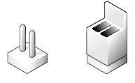
A jumper is referred to as open or unjumpered when the plug is pushed down over only one pin or if there is no plug at all. When the plug is pushed down over two pins, the jumper is referred to as jumpered. The jumper setting is often shown in text as two numbers, such as 1–2. The number 1 is printed on the circuit board with a triangle so that you can identify each pin number based on the location of pin 1.
Figure A-2 shows the location and default settings of the server-module jumper blocks. See Table A-1 for the designations, default settings, and functions of the jumpers.
Figure A-2 shows the location of the configuration jumpers on the system board. Table A-1 lists the jumper settings.
Figure A-2. System Board Jumpers
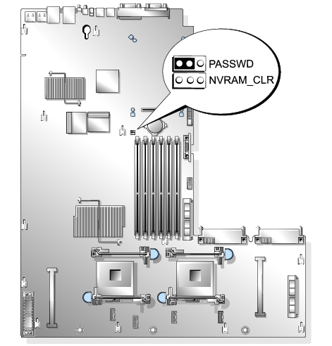
Table A-1. System Board Jumper Settings
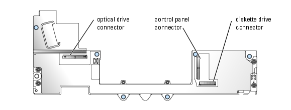
See Figure A-3 and Table A-2 for the location and description of the system board connectors.
Figure A-3. System Board Connectors
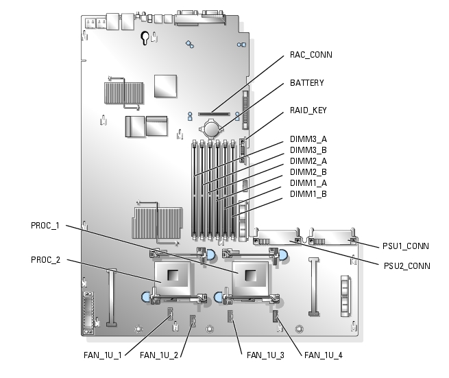
Table A-2. System Board Connectors
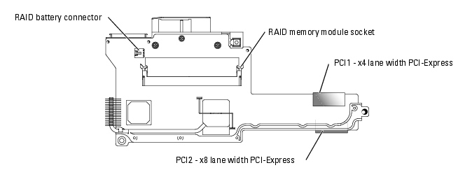
See Figure A-4, Figure A-5, and Figure A-6 for the location and description of the riser card connectors.
Figure A-4. Standard PCI-X Riser Card
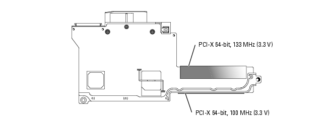
Figure A-5. Optional ROMB PCI-X Riser Card (when available)
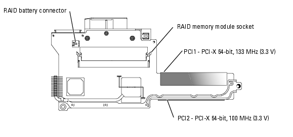
Figure A-6. Optional ROMB PCI-Express Riser Card (when available)
See Figure A-7 for the location and description of the connectors on the SCSI backplane board.
The system's software security features include a system password and a setup password, which are discussed in detail in "Using the System Setup Program" in your User's Guide. The password jumper enables these password features or disables them and clears any password(s) currently in use.

|
CAUTION: See your Product Information Guide for complete information about safety precautions, working inside the computer, and protecting against electrostatic discharge. |
See Figure A-2 to locate the password jumper on the system board.
If necessary, remove the riser card insulator to improve access to the jumper. See "Removing the Riser Card" in "Installing System Components."
The existing passwords are not disabled (erased) until the system boots with the password jumper plug removed. However, before you assign a new system and/or setup password, you must install the jumper plug.

|
NOTE: If you assign a new system and/or setup password with the jumper plug still removed, the system disables the new password(s) the next time it boots. |
See Figure A-2 to locate the password jumper on the system board.
If necessary, remove the riser card insulator to improve access to the jumper, then reinstall the riser card insulator.
To assign a new password using the System Setup program, see "Using the System Setup Program" in your User's Guide.