Back to Contents Page
Dell™ PowerEdge™ 2850 Systems Service-Only Parts Replacement Procedures
 Before You Begin
Recommended Tools
Control Panel Assembly
Expansion-Card Riser Board
SCSI Backplane Board
Back-Fan Tray
System Board
General SCSI Cable-Routing Guidelines
Before You Begin

|
CAUTION: See your Product Information Guide for complete information about safety precautions, working inside the computer, and protecting against electrostatic discharge. |
The procedures in this document require that you remove the cover and work inside the system. While working inside the system, do not attempt to service the system except as explained in this document and in the Installation and Troubleshooting Guide and the User's Guide available on
support.dell.com. Always follow the instructions closely, and ensure that you review all safety precautions in the Product Information Guide.
The Installation and Troubleshooting Guide contains information on system indicators, messages, and codes; system diagnostics; troubleshooting; parts removal and replacement procedures; and jumpers, switches, and connectors.
The User's Guide contains information on the System Setup program.
Recommended Tools
You may need the following items to perform the procedures in this section:
- Key to the bezel
- #2 Phillips screwdriver
- Wrist grounding strap
Control Panel Assembly

|
NOTE: The control panel assembly consists of two separate modules—the control panel and the USB/video-connectors. Use the following instructions to remove and install either module. |
Removing the Control Panel
|
|
CAUTION: Only trained service technicians are authorized to remove the system cover and access any of the components inside the system. See your Product Information Guide for complete information about safety precautions, working inside the computer, and protecting against electrostatic discharge. |
- If applicable, remove the bezel:
- Use the system key to unlock the bezel.
- Press the tab at the left end of the bezel.
- Rotate the left end of the bezel away from the system to release the right end of the bezel.
- Pull the bezel away from the system.
- Turn off the system and attached peripherals, and disconnect the system from the electrical
outlet.
- Open the system:
- Loosen the two thumbscrews that secure the cover to the chassis.
- Slide the top cover backward and grasp the cover at both sides.
- Carefully lift the cover away from the system.
- If applicable, remove the SCSI backplane daughter card.
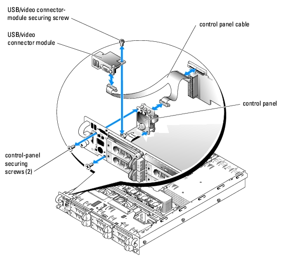
- Remove the USB/video-connector module securing screw and remove the module. See
Figure 1-1.
- Remove the two control-panel securing screws and remove the control panel.
- Disconnect the control panel from the control panel cable.
Figure 1-1. Control Panel Removal
Installing the Control Panel
|
|
CAUTION: Only trained service technicians are authorized to remove the system cover and access any of the components inside the system. See your Product Information Guide for complete information about safety precautions, working inside the computer, and protecting against electrostatic discharge. |
- Connect the control panel to the control panel cable. See Figure 1-1.
- Slide the control panel into the chassis and secure it with the two control-panel securing
screws. See Figure 1-1.
- Replace the USB/video-connector module and secure it with the USB/video-connector
module securing screw. See Figure 1-1.
- If applicable, replace the SCSI backplane daughter card.
- Close the system.
- If applicable, install the bezel.
Expansion-Card Riser Board
Removing the Expansion-Card Riser Board
|
|
CAUTION: Only trained service technicians are authorized to remove the system cover and access any of the components inside the system. See your Product Information Guide for complete information about safety precautions, working inside the computer, and protecting against electrostatic discharge. |
- If applicable, remove the bezel:
- Use the system key to unlock the bezel.
- Press the tab at the left end of the bezel.
- Rotate the left end of the bezel away from the system to release the right end of the bezel.
- Pull the bezel away from the system.
- Turn off the system and attached peripherals, and disconnect the system from the electrical
outlet.
- Open the system:
- Loosen the two thumbscrews that secure the cover to the chassis.
- Slide the top cover backward and grasp the cover at both sides.
- Carefully lift the cover away from the system.
- Remove the expansion-card cage.
- Disconnect the SCSI cable(s) from the SCSI connector(s).
Note the relative location of the SCSI cable(s) to ensure that you properly reconnect the cable(s) to the correct connector(s).
- Remove all expansion cards from the expansion-card slots.
- If applicable, remove the RAID memory module.
- If applicable, disconnect the RAID battery cable.
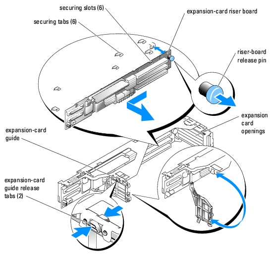
- Press both release tabs on the expansion-card guide and swing open the guide. See Figure 1-2.
- Remove the expansion-card riser board:
- Pull the expansion-card riser release pin. See Figure 1-2.
- While pulling the release pin, slide the riser board away from the expansion card
openings.
- Lift the riser board from the six securing tabs.
Figure 1-2. Expansion-Card Riser Removal
Installing the Expansion-Card Riser Board
|
|
CAUTION: Only trained service technicians are authorized to remove the system cover and access any of the components inside the system. See your Product Information Guide for complete information about safety precautions, working inside the computer, and protecting against electrostatic discharge. |
- Place the riser board in the expansion-card cage so that the six securing tabs are fully inserted
in the six securing slots on the riser board. See Figure 1-2.
- Slide the riser board toward the expansion card openings until you feel the riser-board release
pin snap into place.
- Close the expansion-card guide.
- If applicable, connect the RAID battery cable.
- If applicable, install the RAID memory module.
- Install all expansion cards in the expansion-card slots.
- Connect the SCSI cable(s) to the SCSI connector(s).
- Replace the expansion-card cage.
- Close the system.
- If applicable, install the bezel.
SCSI Backplane Board
Removing the SCSI Backplane Board
|
|
CAUTION: Only trained service technicians are authorized to remove the system cover and access any of the components inside the system. See your Product Information Guide for complete information about safety precautions, working inside the computer, and protecting against electrostatic discharge. |
- If applicable, remove the bezel:
- Use the system key to unlock the bezel.
- Press the tab at the left end of the bezel.
- Rotate the left end of the bezel away from the system to release the right end of the bezel.
- Pull the bezel away from the system.
- Turn off the system and attached peripherals, and disconnect the system from the electrical
outlet.
- Open the system:
- Loosen the two thumbscrews that secure the cover to the chassis.
- Slide the top cover backward and grasp the cover at both sides.
- Carefully lift the cover away from the system.
- If applicable, remove the optical drive.
- If applicable, remove the diskette drive.
- If applicable, remove the internal SCSI tape drive.
- Remove the SCSI hard drives.
|
|
NOTE: To properly reinstall the hard drives, ensure that you record which hard drive you remove from which bay. |
- Disconnect the SCSI cable(s) and control panel cable from the backplane connectors.
- If applicable, remove the SCSI backplane daughter card.
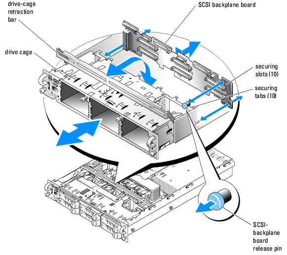
- Raise the drive-bay retraction bar and swing it toward the front of the chassis. See Figure 1-3.
- To ensure there is enough space between the system board to remove the backplane board,
gently pull the drive cage out until it stops.
- Remove the SCSI backplane board:
- Pull the SCSI-backplane board release pin. See Figure 1-3.
- While pulling the release pin, slide the backplane board to the right until it stops.
- Lift the backplane board from its 10 securing tabs and remove the backplane board from
the chassis.
Figure 1-3. SCSI Backplane Board Removal
Installing the SCSI Backplane Board
|
|
CAUTION: Only trained service technicians are authorized to remove the system cover and access any of the components inside the system. See your Product Information Guide for complete information about safety precautions, working inside the computer, and protecting against electrostatic discharge. |
- Place the backplane board on the back of the drive cage so that all ten of the securing tabs are
fully inserted in the ten securing slots on the backplane board. See Figure 1-3.
- Pull the SCSI-backplane board release pin. See Figure 1-3.
- While pulling the release pin, slide the backplane board to the left until it stops, and then
release the release pin and ensure that it snaps into place.
- Gently push in the drive cage until it stops.
- If applicable, replace the SCSI backplane daughter card.
- Connect the SCSI cable(s) and control panel cable to the backplane connectors.
See "General SCSI Cable-Routing Guidelines" for information about how to properly route and secure SCSI cables.
- Raise the drive-bay retraction bar and swing it back until it is completely flush with the top of
the drive cage.
- Reinstall the SCSI hard drives.
|
|
NOTE: Reinstall the hard drives in the same drive bays from which they were removed. |
- If applicable, replace the internal SCSI tape drive.
- If applicable, replace the diskette drive.
- If applicable, replace the optical drive.
- Close the system.
- If applicable, install the bezel.
Back-Fan Tray
Removing the Back-Fan Tray
|
|
CAUTION: Only trained service technicians are authorized to remove the system cover and access any of the components inside the system. See your Product Information Guide for complete information about safety precautions, working inside the computer, and protecting against electrostatic discharge. |
- If applicable, remove the bezel:
- Use the system key to unlock the bezel.
- Press the tab at the left end of the bezel.
- Rotate the left end of the bezel away from the system to release the right end of the bezel.
- Pull the bezel away from the system.
- Turn off the system and attached peripherals, and disconnect the system from the electrical
outlet.
- Open the system:
- Loosen the two thumbscrews that secure the cover to the chassis.
- Slide the top cover backward and grasp the cover at both sides.
- Carefully lift the cover away from the system.
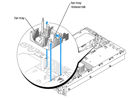
- Remove the two back fans.
- Press the fan-tray release tab. See Figure 1-4.
- Lift the fan tray straight up and out of the system.
Figure 1-4. Removing the Back Fan Tray
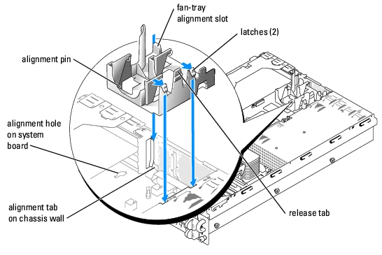
Installing the Back-Fan Tray
- Align the fan-tray alignment slot with the alignment tab on the side of the chassis wall. See
Figure 1-5.
- Align the alignment pin on the bottom of the fan tray with the alignment hole on the system
board.
- Slide the fan tray straight down.
- Press the two left latches until the release tab securely snaps into its securing slot.
Figure 1-5. Installing the Back Fan Tray
- Replace the two back fans.
- Close the system.
- If applicable, install the bezel.
System Board
Removing the System Board
|
|
CAUTION: Only trained service technicians are authorized to remove the system cover and access any of the components inside the system. See your Product Information Guide for complete information about safety precautions, working inside the computer, and protecting against electrostatic discharge. |
- If applicable, remove the bezel:
- Use the system key to unlock the bezel.
- Press the tab at the left end of the bezel.
- Rotate the left end of the bezel away from the system to release the right end of the bezel.
- Pull the bezel away from the system.
- Turn off the system and attached peripherals, and disconnect the system from the electrical
outlet.
- Open the system:
- Loosen the two thumbscrews that secure the cover to the chassis.
- Slide the top cover backward and grasp the cover at both sides.
- Carefully lift the cover away from the system.
- Remove the expansion-card cage.
- Remove any cables from the system board.
- Remove the back fans and the back-fan tray.
- Remove the front fans.
- If applicable, remove the RAC card.
- Remove the memory modules.
|
|
NOTE: While removing the memory modules, record the memory module socket locations to ensure proper installation. |
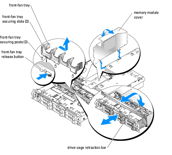
- Remove the memory module cover. See Figure 1-6.
- If applicable, remove the RAID key.
- Remove the front fans.
- Remove the heatsink(s) and microprocessor(s).
- Raise the drive-cage retraction bar and swing it toward the front of the chassis to disengage
the SCSI backplane from the system board.
- Remove the front-fan tray:
- Press and hold the front-fan tray release button. See Figure 1-6.
- Slide the front-fan tray to the right until it stops.
- Lift the front-fan tray from its three securing posts.
Figure 1-6. Front-Fan Tray and Memory Module Cover Removal
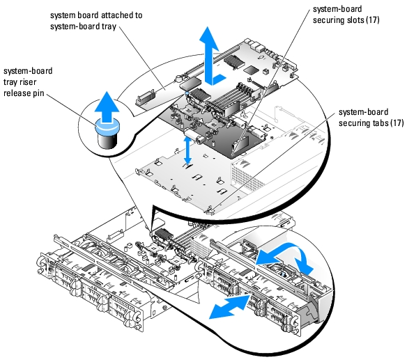
- Remove the system board:
- Pull the system-board tray riser release pin. See Figure 1-7.
- While pulling the release pin, slide the system-board tray toward the front of the chassis.
- Lift up the system-board tray and remove it from the chassis.
Figure 1-7. System Board Removal
Installing the System Board
|
|
CAUTION: Only trained service technicians are authorized to remove the system cover and access any of the components inside the system. See your Product Information Guide for complete information about safety precautions, working inside the computer, and protecting against electrostatic discharge. |
- Lower the system-board tray until the tray sits flat on the bottom of the chassis.
- Ensure that all 17 system-board securing tabs are fully inserted into the 17 system-board
securing slots. See Figure 1-7.
- Slide the system-board tray toward the back of the chassis until it locks into position.
- Replace the front-fan tray:
- Place the three front-fan tray securing slots over the three securing posts. See Figure 1-6.
- Slide the front-fan tray to the left until it locks into position.
- Raise the drive-bay retraction bar and swing it toward the back of the chassis until it is
completely flush with the top of the drive cage.
- Replace the heatsink(s) and microprocessor(s).
- Replace the front fans.
- If applicable, replace the RAID key.
- Replace the memory modules and the memory module cover.
- If applicable, replace the RAC card.
- Replace the back-fan tray and the back fans.
- Replace the expansion-card cage.
- Connect any cables to the system board.
- Close the system.
- If applicable, install the bezel.
General SCSI Cable-Routing Guidelines
|
|
CAUTION: Only trained service technicians are authorized to remove the system cover and access any of the components inside the system. See your Product Information Guide for complete information about safety precautions, working inside the computer, and protecting against electrostatic discharge. |
This section provides general guidelines about how to properly route SCSI cables inside the system.
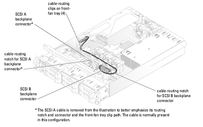
SCSI A and B Backplane Connections
Figure 1-8 illustrates how to properly route cables that attach between the SCSI connectors on the backplane and the SCSI connectors on the expansion-card riser board.
Proper SCSI cable-routing guidelines for this configuration are listed below:
- When you attach a cable to either the SCSI A or B backplane connector, ensure that the cable is placed in the respective cable-routing notch on the backplane. Doing so allows the top cover to be replaced.
- Ensure that the cable(s) is inserted into the cable-routing clips on the front-fan tray. This secures the cable in place and also helps prevent air-flow impedance.
Figure 1-8. Backplane SCSI Connections to the Expansion-Card Riser Board
SCSI cable-routing guidelines for properly routing a cable that connects between a SCSI connector on the backplane and an optional controller card are listed below:
- When connecting a cable to either the SCSI A or B backplane connector, ensure that the cable is placed in the respective cable-routing notch on the backplane. Doing so allows the top cover to be replaced. See Figure 1-8 for the locations of the backplane cable-routing notches.
- Ensure that the cable(s) is inserted into the cable-routing clips on the front-fan tray and in the three cable-routing clips on top of the memory module shroud. This secures the cable in place and also helps prevent air-flow impedance. See Figure 1-8 for the locations of the front-fan cable-routing clips and see Figure 1-9 for the location of the three memory module shroud cable-routing clips.
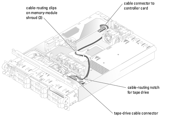
Optional Internal Tape Drive Connections
Figure 1-9 illustrates how to properly route a cable that attaches between an optional internal tape drive and an optional controller card.
Proper SCSI cable-routing guidelines for this configuration are listed below:
- When attaching a cable to the tape drive interface connector, ensure that the cable is placed in the tape-drive cable-routing notch on the backplane. Doing so allows the top cover to be replaced.
- Ensure that the cable is inserted into the three cable-routing clips on top of the memory module shroud. This secures the cable in place and also helps prevent air-flow impedance.
|
|
NOTE: If you are connecting the tape drive to a SCSI connector on the system's expansion-card riser board, route the cable through the cable-routing clips on the front-fan tray. See Figure 1-8 for the locations of the cable-routing clips on the front-fan tray. |
Figure 1-9. Internal Tape Drive Connections to a Controller Card
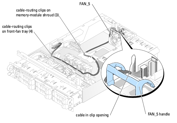
Optional External SCSI Connection
Figure 1-10 illustrates how to properly route an optional external SCSI cable to the expansion-card riser connectors.
Proper SCSI cable-routing guidelines for this configuration are listed below:
- After mounting the external SCSI cable connector in the back-panel connector slot, raise the handle on FAN_5, insert the cable into the clip opening on the back-fan tray, and then close the fan handle. This secures the back end of the cable and also helps prevent air-flow impedance.
- Ensure that the cable is inserted into the three cable-routing clips on top of the memory module shroud. This secures the cable in place and also helps prevent air-flow impedance.
- Ensure that the cable is inserted into the cable-routing clips on the front-fan tray. This secures the cable in place and also helps prevent air-flow impedance.
Figure 1-10. Optional External SCSI Connections
Back to Contents Page