 Before You Begin
The procedures in this guide require that you remove the cover and work inside the system. While working inside the system, do not attempt to service the system except as explained in this manual and elsewhere in the system documentation. Always follow the instructions closely and review all of the procedures in "Safety Instructions" in the System Information Guide.

|
CAUTION: See the System Information Guide for complete information about safety precautions, working inside the computer, and protecting against electrostatic discharge. |
Unless otherwise noted, each procedure assumes that the following conditions exist:
When there is no replacement procedure provided, use the removal procedure in reverse order to install the replacement part.
 |
NOTE: To remove or replace all other components in your system, see the system Installation and Troubleshooting Guide. |
You may need the following items to perform the procedures in this section:
|
|
CAUTION: See the System Information Guide for complete information about safety precautions, working inside the computer, and protecting against electrostatic discharge. |
Figure 1. Removing the I/O Panel

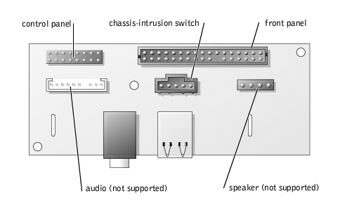
When installing the new I/O panel, note the proper locations of the cables. See Figure 2.
Figure 2. I/O Panel Cable Connectors
|
|
CAUTION: See the System Information Guide for complete information about safety precautions, working inside the computer, and protecting against electrostatic discharge. |
One tab is located inside the optical drive bay near the system cover hinge, and two tabs are located near the I/O panel. See Figure 3.
Figure 3. Removing the Front Bezel
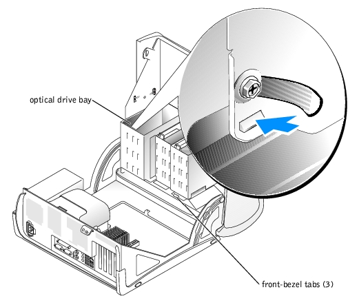
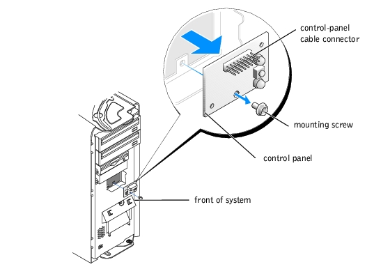
Figure 4. Removing the Control Panel
|
|
CAUTION: See the System Information Guide for complete information about safety precautions, working inside the computer, and protecting against electrostatic discharge. |
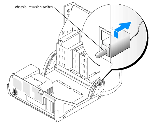
Note the routing of the chassis-intrusion cable as you remove it from the chassis. Chassis hooks may hold the cable in place inside the chassis.
Figure 5. Removing the Chassis-Intrusion Switch
|
NOTE: For instructions on using the System Setup program, see the system User's Guide. |
|
NOTE: The default is Enabled-Silent. |
|
NOTE: If a setup password has been assigned by someone else, contact the network administrator for information on resetting the chassis-intrusion detector. |
|
|
CAUTION: See the System Information Guide for complete information about safety precautions, working inside the computer, and protecting against electrostatic discharge. |
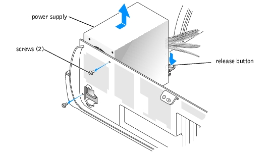
Figure 6. Removing the Power Supply
|
|
CAUTION: See the System Information Guide for complete information about safety precautions, working inside the computer, and protecting against electrostatic discharge. |
|
|
CAUTION: The heat sink can get hot during operation. To avoid burns, ensure that the system has sufficient time to cool before removing the system board. |
 |
NOTICE: The system board and metal tray are connected and are removed as one piece. |
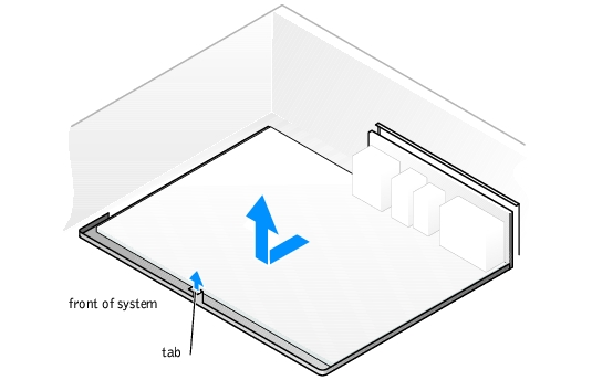
Figure 7. Removing the System Board
See "Jumpers and Connectors" in the system Installation and Troubleshooting Guide.
|
NOTE: Some components and connectors on the replacement system board may be in different locations than the corresponding connectors on the removed system board. |
To confirm the location and function of the connectors on the system board, see "Jumpers and Connectors" in the system Installation and Troubleshooting Guide.