 Jumpers—A General Explanation
Dell™ PowerEdge™ 6650 Systems Service Manual
I/O Riser Card Jumpers and Connectors
I/O Board Connectors and PCI Buses
Microprocessor Board Connectors
SCSI Backplane Board Connectors
Peripheral Riser Card Connectors
This section provides specific information about the system jumpers. It also provides some basic information on jumpers and switches and describes the connectors and sockets on the various boards in the system.
Jumpers provide a convenient and reversible way of reconfiguring the circuitry on a printed circuit board. When reconfiguring the system, you may need to change jumper settings on circuit boards or drives.
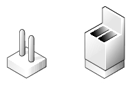
Jumpers are small blocks on a circuit board with two or more pins emerging from them. Plastic plugs containing a wire fit down over the pins. The wire connects the pins and creates a circuit. To change a jumper setting, pull the plug off its pin(s) and carefully fit it down onto the pin(s) indicated. Figure 5-1 shows an example of a jumper.

|
CAUTION: Ensure that the system is turned off before you change a jumper setting. Otherwise, damage to the system or unpredictable results may occur. |
A jumper is referred to as open or unjumpered when the plug is pushed down over only one pin or if there is no plug at all. When the plug is pushed down over two pins, the jumper is referred to as jumpered. The jumper setting is often shown in text as two numbers, such as 1-2. The number 1 is printed on the circuit board so that you can identify each pin number based on the location of pin 1.
Figure 5-2 shows the location and default settings of the system jumper blocks. See Table 5-1 for the designations, default settings, and functions of the system's jumpers.
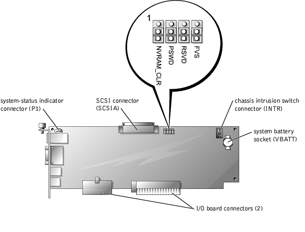
Figure 5-2 shows the location of the configuration jumpers and connectors on the I/O riser card. Table 5-1 and Table 5-2 lists the jumpers and connectors.
Figure 5-2. I/O Riser Card Components
|
Jumper |
Setting |
Description |
|---|---|---|
NVRAM_CLR |
| The configuration settings are retained at system boot. |
| The configuration settings are cleared at next system boot. (If the configuration settings become corrupted to the point where the system will not boot, change the jumper setting to 1–2 and boot the system. Change the jumper setting back to 2–3 before restoring the configuration information.) | |
PSWD |
| The password feature is enabled. |
| The password feature is disabled. | |
RSVD |
| Reserved (do not change). |
FVS |
| Reserved (do not change). |
|
Connector or Socket |
Description |
|---|---|
INTR | Chassis intrusion switch connector. |
P1 | Back-panel system-status indicator (see Figure 5-1). |
SCSIA | This connector attaches to an external SCSI connector on the back panel or to the SCSI backplane board. |
VBATT | System battery socket. |
NOTE: See Figure 5-3 for back-panel connectors provided by the I/O riser card. | |
Figure 5-3 shows the expansion slots, buses, and bus operating speeds.
Figure 5-3. I/O Board Connectors and PCI Buses

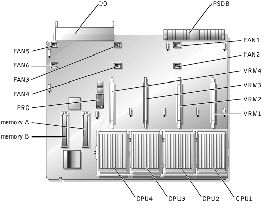
See Figure 5-4 and Table 5-3 for the location and description of microprocessor board components.
Figure 5-4. Microprocessor Board Components
|
Connector or Socket |
Description |
|---|---|
I/O | Interface connector for the microprocessor board and the I/O board |
PSDB | Interface connector for the microprocessor board and the power supply distribution board |
VRMn | VRM connectors 1 through 4 |
CPUn | Microprocessors 1 through 4 |
MEMORYn | Memory riser card connectors A and B |
FANn | Fan connectors 1 through 6 |
PRC | Peripheral riser card connector |
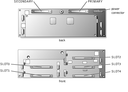
Figure 5-5 shows the location of the connectors on the SCSI backplane board.
Figure 5-5. SCSI Backplane Board Components
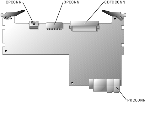
See Figure 5-6 and Table 5-4 for the location and description of peripheral riser card components.
Figure 5-6. Peripheral Riser Card Connectors
|
Connector or Socket |
Description |
|---|---|
CPCONN | Control panel cable connector |
BPCONN | SCSI backplane connector |
CDFDCONN | CD/diskette interface cable connector |
PRCCONN | Microprocessor board connector |