Back to Contents Page
Installing System Components
Dell™ PowerEdge™ 800 Systems Installation and Troubleshooting Guide
 Cooling Shroud
System Fans
Power Supply
Expansion Cards
System Memory
Processor
Installing a RAC Card
System Battery
This section describes how to install the following system components:
- Cooling shroud
- System fans
- Power supply
- Memory modules
- Processor
- Expansion cards
- System battery
Cooling Shroud
Removing the Cooling Shroud

|
CAUTION: See your Product Information Guide for complete information about safety precautions, working inside the computer, and protecting against electrostatic discharge. |
- Turn off the system, including any attached peripherals, and disconnect the system from the
electrical outlet.
- Remove the bezel. See "Removing the Bezel" in "Troubleshooting Your System."
- Lay the system on its right side.
- Remove the cover. See "Removing the Cover" in "Troubleshooting Your System."
- Disconnect the power cables and hard-drive interface cable connectors from the SCSI
backplane (if applicable) or hard drives.
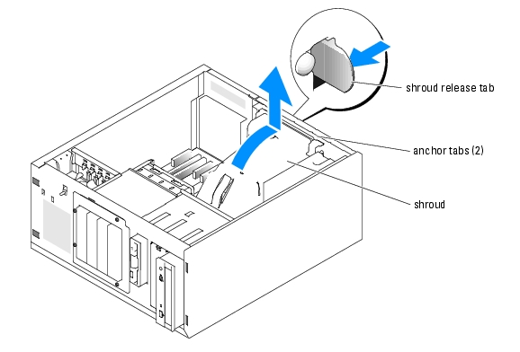
- Press the shroud release tab on the back panel toward the power supply. See Figure 6-1.
- Lift the cooling shroud out of the system. See Figure 6-1.
Figure 6-1. Removing the Cooling Shroud
Installing the Cooling Shroud
- Ensure that no tools or loose parts are left inside the system.
- Align the anchor tabs on the cooling shroud with the notches in the system chassis.
- Reposition the SCSI cable and power cables so they do not obstruct the memory modules and
interfere with installing the cooling shroud.
- Gently lower the cooling shroud until the shroud release tab on the back panel snaps into
place.
- Reconnect the power cable(s) to the SCSI backplane (if applicable) or the hard drive(s).
System Fans
The system includes the following cooling fans:
- Front system fan
- Back system fan
Removing the Front System Fan
|
|
CAUTION: See your Product Information Guide for complete information about safety precautions, working inside the computer, and protecting against electrostatic discharge. |
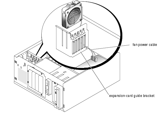
Figure 6-2 illustrates the front system fan inside the system and the fan cable routing hole in the expansion-card guide bracket.
- Turn off the system, including any attached peripherals, and disconnect the system from the
electrical outlet.
- Remove the bezel. See "Removing the Bezel" in "Troubleshooting Your System."
- Lay the system on its right side.
- Remove the cover. See "Removing the Cover" in "Troubleshooting Your System."
- Disconnect the fan power cable from the FRONT_FAN connector on the system board. See
Figure 6-2.
Figure 6-2. Front System Fan Power Cable
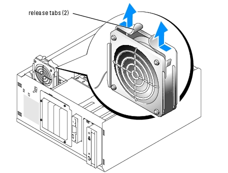
- Compress the two release tabs on the top of the fan assembly and lift the fan assembly away
from the system. See Figure 6-3.
Figure 6-3. Removing and Replacing the Front System Fan
Installing the Front System Fan
|
|
CAUTION: See your Product Information Guide for complete information about safety precautions, working inside the computer, and protecting against electrostatic discharge. |
- Insert the fan power cable through the routing hole in the expansion-card guide bracket. See
Figure 6-2.
- Align the fan assembly with the slots in the chassis and lower the assembly into the chassis.
See Figure 6-3.
- Pull the fan cable through the routing hole in the expansion-card guide bracket. See
Figure 6-2.
- Connect the fan cable connector to the FRONT_FAN connector on the system board.
- Install the cover. See "Replacing the Cover" in "Troubleshooting Your System."
- Stand the system upright.
- Install the bezel. See "Installing the Bezel" in "Troubleshooting Your System."
- Reconnect the system to its electrical outlet and turn the system on, including any attached
peripherals.
Removing the Back System Fan
|
|
CAUTION: See your Product Information Guide for complete information about safety precautions, working inside the computer, and protecting against electrostatic discharge. |
- Turn off the system, including any attached peripherals, and disconnect the system from the
electrical outlet.
- Remove the bezel. See "Removing the Bezel" in "Troubleshooting Your System."
- Lay the system on its right side.
- Remove the cover. See "Removing the Cover" in "Troubleshooting Your System."
- Remove the cooling shroud. See "Removing the Cooling Shroud."
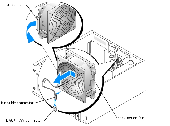
- Disconnect the fan cable from the BACK_FAN connector on the system board. To identify
system board connectors, see Figure A-3.
- Pull the release tab on the fan assembly away from the back panel and slide the fan assembly
about 0.63 cm (0.25 inch) toward the expansion-card slots. See Figure 6-4.
- Pull the fan assembly forward and lift the assembly out of the system. See Figure 6-4.
Figure 6-4. Removing the Back System Fan
Installing the Back System Fan
|
|
CAUTION: See your Product Information Guide for complete information about safety precautions, working inside the computer, and protecting against electrostatic discharge. |
- Align the tabs on the fan bracket with the mounting holes in the back panel and slide the fan
assembly toward the power supply about 0.6 cm (0.25 inch) until the fan bracket release tab
snaps into place. See Figure 6-4.
- Connect the fan cable to the BACK_FAN connector on the system board.
To identify system board connectors, see Figure A-3.
- Install the cooling shroud. See "Installing the Cooling Shroud."
- Install the cover. See "Replacing the Cover" in "Troubleshooting Your System."
- Stand the system upright.
- Install the bezel. See "Installing the Bezel" in "Troubleshooting Your System."
- Reconnect the system to its electrical outlet and turn the system on, including any attached
peripherals.
Power Supply
Removing the Power Supply
|
|
CAUTION: See the Product Information Guide for complete information about safety precautions, working inside the computer, and protecting against electrostatic discharge. |
- Turn off the system and attached peripherals, and disconnect the system from the electrical
outlet.
- Remove the bezel. See "Removing the Bezel" in "Troubleshooting Your System."
- Lay the system on its right side.
- Remove the cover. See "Removing the Cover" in "Troubleshooting Your System."
- Disconnect the DC power cables from the following components:
- POWER CONN connector on the backplane board (if applicable)
- PWR CONN and 12V connectors on the system board
- Hard drives or SCSI backplane board
- Diskette drive (if applicable)
- Optical drive (if applicable)
- Tape backup drive (if applicable)
- Remove the cooling shroud. See "Removing the Cooling Shroud."
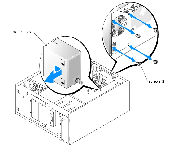
- Remove the four screws securing the power supply to the back panel. See Figure 6-5.
Figure 6-5. Removing the Power Supply
- Slide the power supply toward the front of the system, and then lift the power supply up and
out of the system.
Replacing the Power Supply
- Lower the power supply into the system and align the mounting holes with the holes on the
back panel.
- Install the four screws securing the power supply to the back panel.
- Install the cooling shroud. See "Installing the Cooling Shroud."
- Connect the DC power cables to the following components:
- POWER CONN connector on the backplane board (if applicable)
- PWR CONN and 12V connectors on the system board
- Hard drives or SCSI backplane.
- Diskette drive (if applicable)
- Optical drive (if applicable)
- Tape backup drive (if applicable)
- Install the cover. See "Replacing the Cover" in "Troubleshooting Your System."
- Stand the system upright.
- Install the bezel. See "Installing the Bezel" in "Troubleshooting Your System."
- Reconnect the system to its electrical outlet and turn the system on, including any attached
peripherals.
Expansion Cards
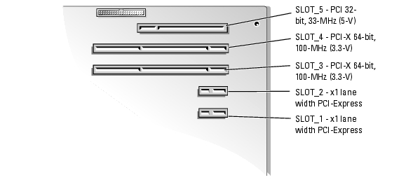
Your system supports up to five full-length expansion cards, installed in connectors on a riser card. The expansion slots are configured as follows:
- Slots 1 and 2 are x1 lane-width PCI-Express expansion slots.
- Slots 3 and 4 are 3.3-V, 64-bit, 100-MHz PCI-X expansion slots. 133-MHz cards installed in these slots will run at 100 MHz.
- Slot 5 is a 5-V, 32-bit, 33-MHz legacy PCI expansion slot.
Figure 6-6 shows the relative locations of the expansion-card slots.

|
NOTICE: If you install a RAC card, it must be installed in PCI slot SLOT_5. |
Figure 6-6. Expansion Slots
Installing an Expansion Card
|
|
CAUTION: See your Product Information Guide for complete information about safety precautions, working inside the computer, and protecting against electrostatic discharge. |
- Unpack the expansion card, and prepare it for installation.
For instructions, see the documentation that accompanied the card.
- Turn off the system, including any attached peripherals, and disconnect the system from the
electrical outlet.
- Remove the bezel. See "Removing the Bezel" in "Troubleshooting Your System."
- Lay the system on its right side.
- Remove the cover. See "Removing the Cover" in "Troubleshooting Your System."
- Remove the filler bracket from the expansion slot.
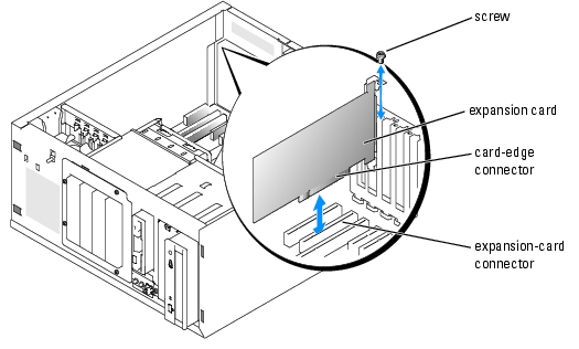
- Install the expansion card. See Figure 6-7.
- Position the expansion card so that the card-edge connector aligns with the expansion-
card connector on the system board.
- Insert the card-edge connector firmly into the expansion-card connector until the card is
fully seated.
- Install the screw that secures the expansion-card bracket to the back panel.
- Connect any cables that should be attached to the card.
See the documentation that accompanied the card for information about its cable connections.
- Install the cover. See "Replacing the Cover" in "Troubleshooting Your System."
- Stand the system upright.
- Install the bezel. See "Installing the Bezel" in "Troubleshooting Your System."
- Reconnect the system to its electrical outlet and turn the system on, including any attached
peripherals.
- Install any device drivers required for the card as described in the documentation for the card.
Figure 6-7. Removing and Installing an Expansion Card
Removing an Expansion Card
|
|
CAUTION: See your Product Information Guide for complete information about safety precautions, working inside the computer, and protecting against electrostatic discharge. |
- Turn off the system, including any attached peripherals, and disconnect the system from the
electrical outlet.
- Remove the bezel. See "Removing the Bezel" in "Troubleshooting Your System."
- Lay the system on its right side.
- Remove the cover. See "Removing the Cover" in "Troubleshooting Your System."
- Disconnect any cables attached to the card.
- Remove the expansion card (see Figure 6-7):
- Remove the screw that secures the expansion-card bracket to the back panel.
- Grasp the expansion card by its top corners, and carefully remove it from the expansion-
card connector.
|
|
NOTICE: You must install a filler bracket over an empty expansion slot to maintain Federal Communications Commission (FCC) certification of the system. The brackets also help keep dust and dirt out of the system and aid in proper cooling and airflow inside the system. |
- If you are removing the card permanently, install a metal filler bracket over the empty
expansion slot opening and close the expansion-card latch.
- Install the cover. See "Replacing the Cover" in "Troubleshooting Your System."
- Stand the system upright.
- Install the bezel. See "Installing the Bezel" in "Troubleshooting Your System."
- Reconnect the system to its electrical outlet and turn the system on, including any attached
peripherals.
System Memory
You can upgrade your system memory to a maximum of 4 GB by installing combinations of 256-MB, 512-MB, or 1-GB 2-way unbuffered ECC DDR 2 400/533 memory modules. The system memory is located on the system board adjacent to the power supply bays. See Figure A-3. The memory module sockets are arranged in two banks on two channels (A and B). The memory module banks are identified as follows:
- Bank 1: DIMM1_A and DIMM1_B
- Bank 2: DIMM2_A and DIMM2_B
General Memory Module Installation Guidelines
- If only one memory module is installed, it must be installed in socket DIMM1_A.
- If two or more memory modules are installed, they must be installed in pairs of matched memory size, speed, and technology.
Table 6-1 shows examples of different memory configurations.
Table 6-1. Sample Memory Configurations
|
Total Memory
|
DIMM1_A
|
DIMM2_A
|
DIMM1_B
|
DIMM2_B
|
Memory Mode
|
|---|
256 MB
| 256 MB
| none
| none
| none
| Single channel
|
512 MB
| 256 MB
| none
| 256 MB
| none
| Dual channel, interleaved
|
512 MB
| 512 MB
| none
| none
| none
| Single channel
|
1 GB
| 256 MB
| 256 MB
| 256 MB
| 256 MB
| Dual channel, interleaved
|
1 GB
| 512 MB
| none
| 512 MB
| none
| Dual channel, interleaved
|
1 GB
| 1 GB
| none
| none
| none
| Single channel
|
1.5 GB
| 512 MB
| 256 MB
| 512 MB
| 256 MB
| Dual channel, interleaved
|
2 GB
| 512 MB
| 512 MB
| 512 MB
| 512 MB
| Dual channel, interleaved
|
2 GB
| 1 GB
| none
| 1 GB
| none
| Dual channel, interleaved
|
3 GB
| 1 GB
| 512 MB
| 1 GB
| 512 MB
| Dual channel, interleaved
|
4 GB
| 1 GB
| 1 GB
| 1 GB
| 1 GB
| Dual channel, interleaved
|
Installing Memory Modules
|
|
CAUTION: See your Product Information Guide for complete information about safety precautions, working inside the computer, and protecting against electrostatic discharge. |
- Turn off the system, including any attached peripherals, and disconnect the system from the
electrical outlet.
- Remove the bezel. See "Removing the Bezel" in "Troubleshooting Your System."
- Lay the system on its right side.
- Remove the cover. See "Removing the Cover" in "Troubleshooting Your System."
- Remove the cooling shroud. See "Removing the Cooling Shroud."
- Locate the memory module sockets. See Figure A-3.
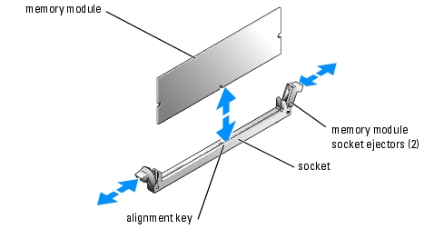
- Press the ejectors on the memory module socket down and out, as shown in Figure 6-8, to
allow the memory module to be inserted into the socket.
Figure 6-8. Installing and Removing a Memory Module
- Align the memory module's edge connector with the alignment key on the memory module
socket, and insert the memory module in the socket.

|
NOTE: The memory module socket has an alignment key that allows you to install the memory module in the socket in only one way. |
- Press down on the memory module with your thumbs while pulling up on the ejectors with
your index fingers to lock the memory module into the socket.
When the memory module is properly seated in the socket, the ejectors on the memory module socket align with the ejectors on the other sockets that have memory modules installed.
- Repeat step 6 through step 9 of this procedure to install the remaining memory modules. See
Table 6-1 for sample memory configurations.
- Install the cooling shroud. See "Installing the Cooling Shroud."
- Install the cover. See "Replacing the Cover" in "Troubleshooting Your System."
- Stand the system upright.
- Install the bezel. See "Installing the Bezel" in "Troubleshooting Your System."
- Reconnect the system to its electrical outlet and turn the system on, including any attached
peripherals.
- (Optional) Press <F2> to enter the System Setup program, and check the System Memory
setting on the main System Setup screen.
The system should have already changed the value to reflect the newly installed memory.
- If the value is incorrect, one or more of the memory modules may not be installed properly.
Repeat step 1 through step 16 of this procedure, checking to ensure that the memory modules
are firmly seated in their sockets.
- Run the system memory test in the system diagnostics. See "Running the System
Diagnostics."
Removing Memory Modules
|
|
CAUTION: See your Product Information Guide for complete information about safety precautions, working inside the computer, and protecting against electrostatic discharge. |
- Turn off the system, including any attached peripherals, and disconnect the system from the
electrical outlet.
- Remove the bezel. See "Removing the Bezel" in "Troubleshooting Your System."
- Lay the system on its right side.
- Remove the cover. See "Removing the Cover" in "Troubleshooting Your System."
- Remove the cooling shroud. See "Removing the Cooling Shroud."
- Locate the memory module sockets. See Figure A-3.
- Press down and out on the ejectors on each end of the socket until the memory module pops
out of the socket. See Figure 6-8.
- Install the cooling shroud. See "Installing the Cooling Shroud."
- Install the cover. See "Replacing the Cover" in "Troubleshooting Your System."
- Stand the system upright.
- Install the bezel. See "Installing the Bezel" in "Troubleshooting Your System."
Processor
You can upgrade the system processor to take advantage of future options in speed and functionality.
The following items are included in the processor upgrade kit:
Removing the Processor
|
|
CAUTION: See your Product Information Guide for complete information about safety precautions, working inside the computer, and protecting against electrostatic discharge. |
- Turn off the system, including any attached peripherals, and disconnect the system from the
electrical outlet.
- Remove the bezel. See "Removing the Bezel" in "Troubleshooting Your System."
- Lay the system on its right side.
- Remove the cover. See "Removing the Cover" in "Troubleshooting Your System."
- Remove the cooling shroud. See "Removing the Cooling Shroud."
|
|
NOTICE: Never remove the heat sink from a processor unless you intend to remove the processor. The heat sink is necessary to maintain proper thermal conditions. |
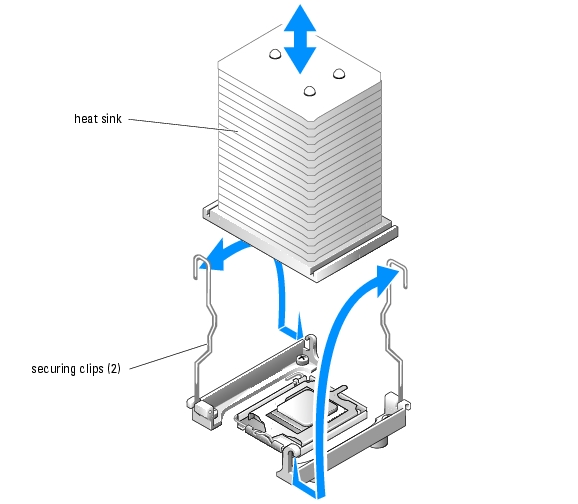
- Remove the heat sink. See Figure 6-9.
- Open one securing clip by pressing the end of the clip down and away from the retention
until it clears the securing tab on the retention module, and then lift the clip up.
- Repeat step a for the remaining securing clip.
- Rotate the heat sink slightly and then lift the heat sink off the processor. Do not pry the
processor off the heat sink.
Figure 6-9. Removing the Heat Sink
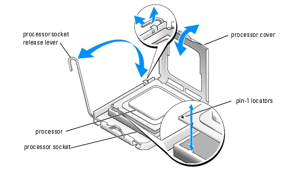
- Press down on the processor socket release lever, then pull the release lever upward to the fully
open position. See Figure 6-10.
- Open the processor cover. See Figure 6-10.
- Lift the processor vertically out of the socket. Leave the processor cover and release lever in
the open position so that the socket is ready for the new processor. See Figure 6-10.
Figure 6-10. Replacing the Processor
Installing a Processor
|
|
CAUTION: See your Product Information Guide for complete information about safety precautions, working inside the computer, and protecting against electrostatic discharge. |
- Unpack the new processor and heat sink.
- Ensure that the processor socket release lever is in the fully open position.
- Align the pin 1 corners of the processor and socket. See Figure 6-10.
|
|
NOTICE: You must position the processor correctly in the socket to avoid damaging the processor and the system board when you turn on the system. Be careful not to touch or bend the pins on the socket. |
- Set the processor lightly in the socket and ensure that the processor is level in the socket.
When the processor is positioned correctly, press it gently to seat it in the socket.
- Close the processor cover.
- Rotate the release lever back down until it snaps into place, securing the processor cover.
|
|
NOTICE: Do not operate the system without the heat sink installed. The heat sink is required to maintain proper thermal conditions. |
- Remove the thermal grease protective cover from the new heat sink.
If you did not receive a new heat sink with the processor, see "Getting Help."
- Lower the heat sink onto the processor. See Figure 6-9.
- Secure the heat sink to the retention module.
- Gently press down on the heat sink and then press one securing clip to secure it.
- Repeat step a for the remaining securing clip.
- Ensure that the back fan connector is connected to the BACK_FAN connector on the system
board. See Figure A-3.
- Install the cooling shroud. See "Installing the Cooling Shroud."
- Install the cover. See "Replacing the Cover" in "Troubleshooting Your System."
- Stand the system upright.
- Install the bezel. See "Installing the Bezel" in "Troubleshooting Your System."
- Reconnect the system to its electrical outlet and turn the system on, including any attached
peripherals.
- Enter the System Setup program, and ensure that the processor options match the new
system configuration. See "Using the System Setup Program" in your User's Guide.
As the system boots, it detects the presence of the new processor and automatically changes the system configuration information in the System Setup program. A message similar to the following appears:
One 2.3 GHz Processor, Processor Bus: 533 MHz, L2 cache 256 KB Advanced
- Confirm that the top line of the system data area in the System Setup program correctly
identifies the installed processor. See "Using the System Setup Program" in your User's Guide.
- Exit the System Setup program.
- Ensure that your system is running the latest BIOS version.
You can download the latest BIOS version from the Dell Support website located at support.dell.com
- Run the system diagnostics to verify that the new processor is operating correctly.
See "Running the System Diagnostics" for information on running the diagnostics and troubleshooting any problems that may occur.
Installing a RAC Card
|
|
CAUTION: See your Product Information Guide for complete information about safety precautions, working inside the computer, and protecting against electrostatic discharge. |
- Turn off the system, including any attached peripherals, and disconnect the system from the
electrical outlet.
- Remove the bezel. See "Removing the Bezel" in "Troubleshooting Your System."
- Lay the system on its right side.
- Remove the cover. See "Removing the Cover" in "Troubleshooting Your System."
- Install the RAC card in PCI expansion slot SLOT_5.
See "Installing an Expansion Card" for information on installing the card.
- Connect the cable from the RAC card to connector RAC_CONN on the system board. See
Figure A-3.
- Install the cover. See "Replacing the Cover" in "Troubleshooting Your System."
- Stand the system upright.
- Install the bezel. See "Installing the Bezel" in "Troubleshooting Your System."
- Reconnect the system to its electrical outlet and turn the system on, including any attached
peripherals.
- Enter the System Setup program and verify that the setting for the RAC card has changed to
reflect the presence of the card. See "Using the System Setup Program" in your User's Guide.
See the RAC card documentation for information on configuring and using the RAC card.
System Battery
Replacing the System Battery
|
|
CAUTION: See your Product Information Guide for complete information about safety precautions, working inside the computer, and protecting against electrostatic discharge. |
- Enter the System Setup program and record the option settings on the System Setup screens.
See "Using the System Setup Program" in the User's Guide.
- Turn off the system, including any attached peripherals, and disconnect the system from the
electrical outlet.
- Remove the bezel. See "Removing the Bezel" in "Troubleshooting Your System."
- Lay the system on its right side.
- Remove the cover. See "Removing the Cover" in "Troubleshooting Your System."
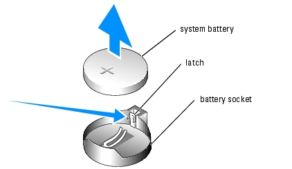
- Remove the system battery. See Figure A-3 for the battery socket location on the system
board.
- Pull the latch away from the battery. See Figure 6-11
- Lift the battery out of the battery socket.
Figure 6-11. Removing the System Battery
|
|
NOTICE: You must install the new system battery with the side labeled "+" facing up. See Figure 6-11. |
- To install the new system battery, hold the battery with the side labeled "+" facing up, and
then press the battery straight down into the battery socket until the latch snaps into place
over the edge of the battery. See Figure 6-11.
- Install the cover. See "Replacing the Cover" in "Troubleshooting Your System."
- Stand the system upright.
- Install the bezel. See "Installing the Bezel" in "Troubleshooting Your System."
- Reconnect the system to its electrical outlet and turn the system on, including any attached
peripherals.
- Enter the System Setup program to confirm that the battery operates properly.
- From the main screen, select System Time to enter the correct time and date.
- Re-enter any system configuration information that is no longer displayed on the System
Setup screens, and then exit the System Setup program.
- To test the newly installed battery, see "Troubleshooting the System Battery" in
"Troubleshooting Your System."
Back to Contents Page