 Serial Port
Dell™ PowerVault™ 715N Systems User's Guide
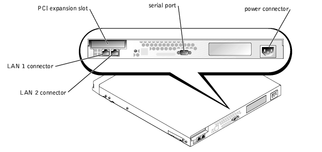
The I/O ports and connectors on the back panel of the system are the gateways through which the system communicates with the network. Figure B-1 identifies the I/O ports and connectors for your appliance.
Figure B-1. I/O Ports and Connectors
The serial port uses nine-pin D-subminiature connectors on the back panel. Most software uses the term COM (for communications) and a number to designate a serial port (for example, COM1).
Use COM1 to connect to a server for console redirection or RAS connection. For more information about console redirection and RAS, see your System Administrator's Guide.
If you reconfigure your hardware, you might need pin number and signal information for the serial port connectors. Figure B-2 illustrates the pin numbers for the serial port connectors, and Table B-1 defines the pin assignments and interface signals for the serial port connector.
Figure B-2. Pin Numbers for the Serial Port Connector

|
Pin |
Signal |
I/O |
Definition |
|---|---|---|---|
1 | DCD | I | Data carrier detect |
2 | SIN | I | Serial input |
3 | SOUT | O | Serial output |
4 | DTR | O | Data terminal ready |
5 | GND | N/A | Signal ground |
6 | DSR | I | Data set ready |
7 | RTS | O | Request to send |
8 | CTS | I | Clear to send |
9 | RI | I | Ring indicator |
Shell | N/A | N/A | Chassis ground |
Your system has two integrated 10/100–megabit-per-second (Mbps) NIC. The NIC provides all the functions of a separate network expansion card and supports both the 10BASE-T and 100BASE-TX Ethernet standards.
Your system's RJ-45 NIC connector is designed for attaching an unshielded twisted pair (UTP) Ethernet cable equipped with standard RJ-45-compatible plugs. Press one end of the UTP cable into the NIC connector until the plug snaps securely into place. Connect the other end of the cable to an RJ-45 jack wall plate or an RJ-45 port on a UTP concentrator or hub, depending on your network configuration. Observe the following cabling restrictions for 10BASE-T and 100BASE-TX networks.
 |
NOTICE: To avoid line interference, voice and data lines must be in separate sheaths. |