Back to Contents Page
Installing Equipment in the Rack: Dell™ PowerEdge™
24U Rack Installation Guide
Overview • Before
You Begin • Safety Precautions • Recommended Tools • Installing
Cage Nuts • Installing a UPS • Installing a Switch Box • Installing a Filler Panel • Replacing the Rack Doors
This section describes how to install a UPS, switch box, and other
equipment in the rack. For instructions on installing a Dell server, storage system, or
other Dell product in the rack, refer to the documentation supplied with the rack kit for
that product.
Carefully read the safety precautions in the following sections
before you begin installing the equipment in the rack.
 |
WARNING: Installing components in the rack
without the front stabilizer installed could allow the rack to tip over and cause bodily
injury under certain circumstances. Always install the stabilizer before installing
components in the rack. |
The stabilizer helps prevent the possibility of the rack tipping
over when a component is installed and then pulled out of the rack to the fully extended
position of the slide assemblies. Refer to Setting
Up the Rack, for instructions on installing the stabilizer.
 |
WARNING: Install the heaviest components in
the lowest possible portion of the rack to prevent the rack from tipping over and injuring
someone when the component is pulled out of the rack on the slide assemblies.
|
 |
WARNING: After installing components in a
rack, never pull more than one component out of the rack on its slides at one time. The
weight of more than one component extended on the slide assemblies could cause the rack to
tip over and injure someone. |
To install the rack kit, you should have the following tools:
- A 3/8-inch nut driver
- A 3/8-inch wrench
- A 7/16-inch wrench
- Diagonal cutters
- A #2 Phillips screwdriver
- The cage-nut installation tool included in the rack hardware kit
- A steel measuring tape
- Safety glasses
 |
CAUTION: Always wear safety glasses when
installing cage nuts. |
Cage nuts are used to secure computers, storage systems, and other
components to the vertical rails in the rack. Perform the following steps to install cage
nuts:
- Insert the lower lip of the cage nut over the bottom of the opening
in the back of a rail as shown in Figure 1, Installing a Cage Nut.
Then insert the small end of the cage-nut installation tool through the opening in the
rail (from the front), and hook the tool over the top lip of the cage nut.
- Push in on the cage nut while rotating the tool up and pulling the
tool back toward you until the top lip of the cage nut snaps into position.
- Repeat this process to install the other cage nuts in the appropriate
locations.
Figure 1. Installing a Cage Nut
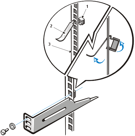
1 |
cage nut |
2 |
cage-nut installation tool |
3 |
vertical rail |
Perform the following steps to install an APC 1400 RM, 2200 RM or
3000 RM UPS.
 |
WARNING: The APC 1400 RM UPS, 2200 RM UPS, and
3000 RM UPS weigh approximately 25.0 kg (55 lb), 54.5 kg (120 lb), and 58.9 kg (130 lb),
respectively. Always install the UPS in the lowest portion of the rack.
|
 |
WARNING: To prevent
personal injury due to the weight of the UPS, never attempt to install or remove the UPS
by yourself. Be sure to use proper lifting techniques to prevent back injury. |
- If you have purchased a UPS interface card, install the card now.
- Using a Phillips screwdriver, remove the two screws securing the
accessory slot cover to the UPS back panel and remove the slot cover.
- Insert the UPS interface card into the UPS. Orient the card as shown
in Figure 2, Installing a UPS Interface Card in an APC 1400 RM UPS.
- Secure the UPS interface card with the two Phillips screws you
removed in substep a.
For more information, refer to the documentation provided with the UPS interface card.
Figure 2. Installing a UPS Interface Card in
an APC 1400 RM UPS
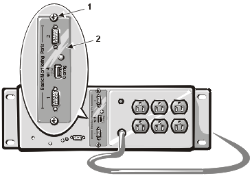
1 |
screws (2) |
2 |
UPS interface card
|
- Install eight cage nuts in the four vertical rails of the rack.
- For an APC 1400 RM UPS, install a cage nut in the second and eighth
holes from the bottom of each vertical rail.
- For an APC 2200 RM or 3000 RM UPS, install a cage nut in the third
and thirteenth holes from the bottom of each vertical rail.
See Installing Cage Nuts for
instructions.
- If you are installing an APC 2200 RM or 3000 RM UPS, install the two
support brackets in the rack as follows:
- Install two cage nuts on the inside of the flange at each end of the
support bracket (see number 1 in Figure 3, Installing Support Brackets
for the APC 2200 RM or 3000 RM UPS).
Figure 3. Installing
Support Brackets for the APC 2200 RM or 3000 RM UPS
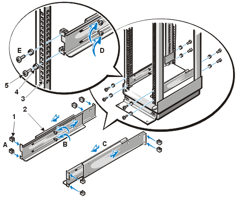
1 |
cage nuts (4 per bracket) |
2 |
support brackets (2) |
3 |
vertical rail |
4 |
washers (4 per bracket) |
5 |
screws (4 per bracket)
|
- Loosen the two Phillips screws holding the two halves of the support
bracket together (see number 2 in Figure 3, Installing Support
Brackets for the APC 2200 RM or 3000 RM UPS).
- Insert the support bracket in the rack, and adjust the length of the
bracket until the flanges at each end fit snugly against the inner sides of the
rack's vertical rails (see number 3 in Figure 3, Installing Support
Brackets for the APC 2200 RM or 3000 RM UPS).
- Retighten the two Phillips screws to lock the two halves of the
support bracket together (see number 4 in Figure 3, Installing Support
Brackets for the APC 2200 RM or 3000 RM UPS).
- Using tape or a marking pen, mark the first and sixth holes from the
bottom of each vertical rail to indicate where the support brackets will be installed.
- With the notched flange facing the front of the rack, position the
support brackets at the locations marked in substep e, and secure the two support brackets
to the vertical rails using four Phillips screws and four metal cup washers per rail (see
number 5 in Figure 3, Installing Support Brackets for the APC 2200 RM
or 3000 RM UPS).
- Set the UPS in the rack.
If you are installing an APC 1400 RM UPS, have two people place the UPS in the
bottom of the rack (see Figure 4, Installing an APC 1400 RM UPS in the
Rack). Support the back of the UPS until you secure the UPS mounting bracket, as
described in step 5.
If you are installing an APC 2200 RM UPS, have two people slide the UPS onto the
support brackets near the bottom of the rack. A third person should hold the rack in
position to prevent it from moving.
Figure 4. Installing an APC 1400 RM UPS in the Rack
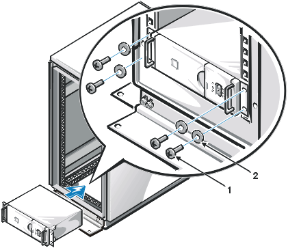
1 |
screws (4) |
2 |
washers (4)
|
- Secure the UPS by installing four 10-32 x 0.625-inch Phillips screws
and four #10 flat metal washers through the four holes in the rack mounting brackets (see Figure 4, Installing an APC 1400 RM UPS in the Rack).
Perform the following steps to install a switch box in the rack:
- Assemble the inner and outer halves of one of the mounting brackets
using two screws and nuts (see Figure 5, Installing the Mounting
Brackets on the Switch Box).
Do not tighten the screws until after you adjust the length of the bracket.
- Insert the mounting bracket in the rack, and adjust the length of the
bracket until the flanges at each end fit snugly against the inner sides of the rack's
vertical rails.
- Using tape or a marking pen, indicate on the rack's vertical rails
where cage nuts should be installed, based on the locations of the upper and lower holes
in the mounting bracket's front and back flanges.
- Remove the bracket from the rack, and tighten the two screws to lock
the two halves of the support bracket together.
- Repeat steps 1 through 4 to adjust the length of the second bracket.
- Install the eight cage nuts supplied with the brackets in the upper
and lower holes in the mounting-bracket flanges.
Install the cage nuts on the inside of the flanges at each end of the mounting bracket.
- Install the two mounting brackets on the switch box using two
Phillips screws per bracket (see Figure 5, Installing the Mounting
Brackets on the Switch Box).
Figure 5. Installing the Mounting Brackets on the Switch
Box
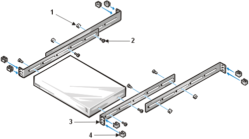
1 |
nuts (4) |
2 |
screws (8) |
3 |
flanges (4) |
4 |
cage nuts (8)
|
- Install the switch box in the rack (see Figure 6,
Installing the Switch Box in the Rack).
When inserting the switch box into the rack, you need to press inward on the back portions
of the mounting brackets for them to clear the front and back vertical rails of the rack.
When installed correctly, the flanges should be on the inside of the front and back
vertical rails.
Figure 6. Installing the Switch Box in the Rack
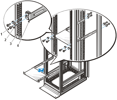
1 |
screws (8) |
2 |
washers (8) |
3 |
vertical rail |
4 |
mounting brackets (2) |
- Secure the switch box to the vertical rails using eight screws and
eight washers (see Figure 6, Installing the Switch Box in the Rack).
You may install optional filler panels to cover unoccupied portions
of the rack enclosure. Perform the following steps to install a filler panel:
- Place the filler panel in the rack, and mark the location on the
front vertical rails where you will install cage nuts to secure the filler panel.
After marking the rails, remove the filler panel.
- Install four 10-32 cage nuts in the vertical rails.
See Installing Cage Nuts for instructions on
installing the cage nuts.
- Press the hinge pins down.
- Position the filler panel in the rack, and install four 10-32 x
.625-inch Phillips screws and washers to secure the filler panel (see Figure
7, Installing a Filler Panel).
Figure 7. Installing a Filler Panel
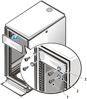
1 |
screws (4) |
2 |
washers (4) |
3 |
filler panel |
Replace the rack's front and back doors by performing the following
steps:
- Lift the front door into position, and align the hinges with the
holes in the rack (see Figure 8, Installing the Doors).
Figure 8. Installing the Doors
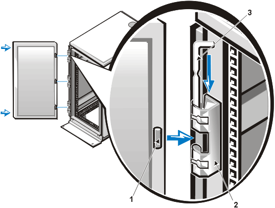
1 |
rack door |
2 |
hinge |
3 |
hinge pin
|
- Line up and then press the door hinges down.
- Close the door latch by rotating the handle counterclockwise until it
stops, push the handle in until it locks in position.
- Repeat steps 1 through 3 to install the back door.
Back to Contents Page


