- INTRODUCTION
EDP introduce the NCR S20GX which replaces the existing NCR S20LX. The case and
interior are redesigned, and many of the component units ARE NOT interchangeable
with the S20LX machines.
- MEC IDENTITY
N-3425 (S20GX) Modified Cabinet
N-3425-PROC (P2-400-100-2L2U6)
400 MHz Pentium II FSB Speed 100Mhz Processor
N-3425-PROC-TERM-100 FSB speed now 100mhz
N-3425-SDRAM (64MB-100) FSB speed now PC100
N-3425-SDRAM (128MB-100) FSB speed now PC100
N-3425-SDRAM (256MB-100) FSB speed now PC100
N-3425-SYSTEM-BOARD-100 FSB speed now 100mhz
N-4071-2200VA (UPS) 2.2 KVA UPS
N-3425-PROC (P2-333-66-SL2WY)
NCR Product System Unit Processor Type Speed FSB Speed Model Type
N- 3425- PROC (P2- 400 100 2L2U6
The above items MUST NOT be fitted into S20LX systems.
- SPECIFICATION
Dimensions hwd approx. 21 x 10 x 19 inches 52 x 24 x 48 cm
Minimum Installation and Service Clearances.
Front 9inch / 22cm Rear 12.2inch / 31cm
Left & Right Sides 23.6inch / 60cm
Max weight: 43.5 Ib 19.77kg
Max heat O / P: 4098 BTU
Noise typically: <45d BA
Power: 200-240 VAC 3.5A 50HZ
NOTE: The S20GX is supplied with a 2.2 KVA UPS
-
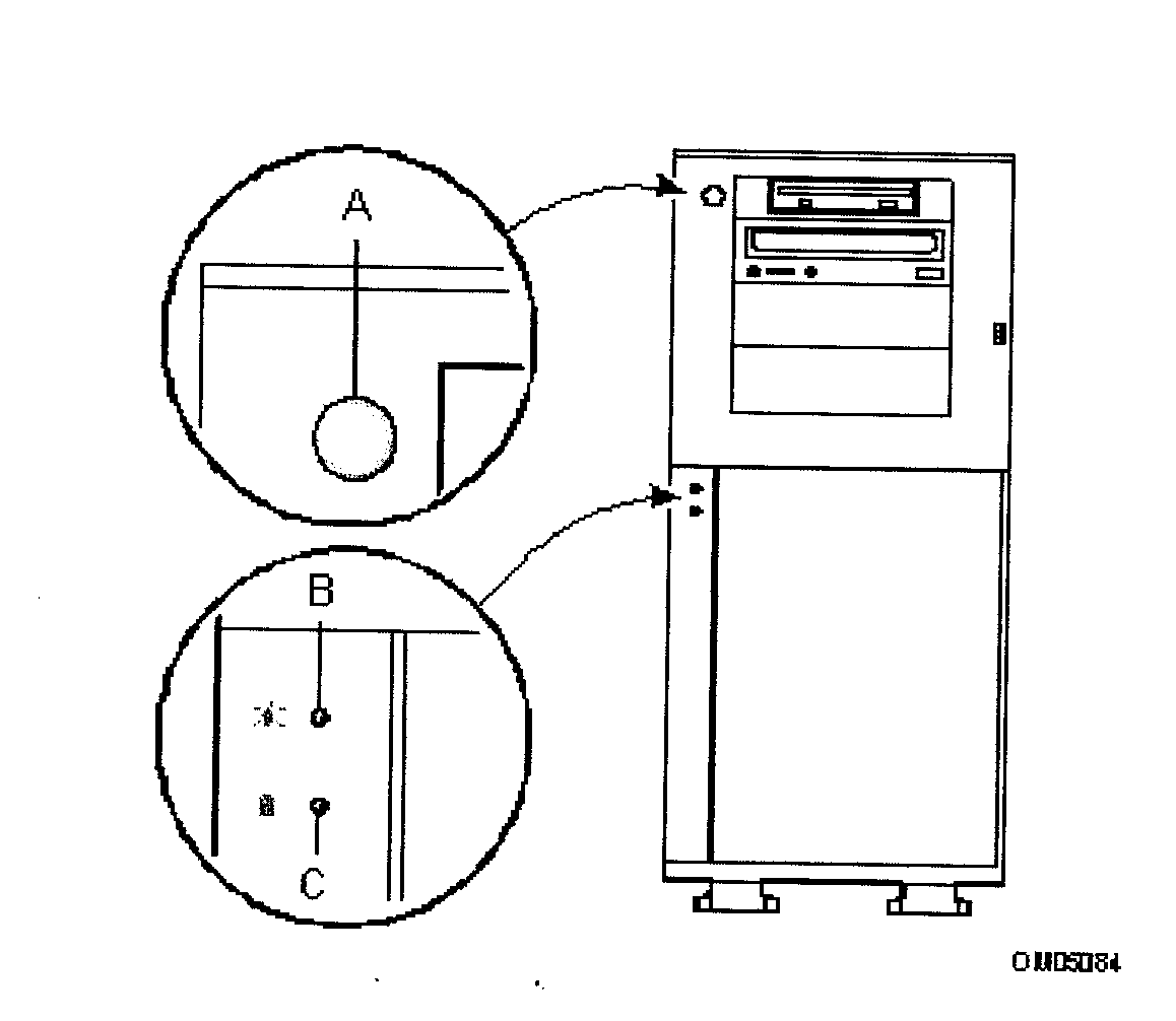
FRONT PANEL
WARNING: The push-button power switch on the front panel does NOT turn off the system
Ac power.

-
BACK PANEL

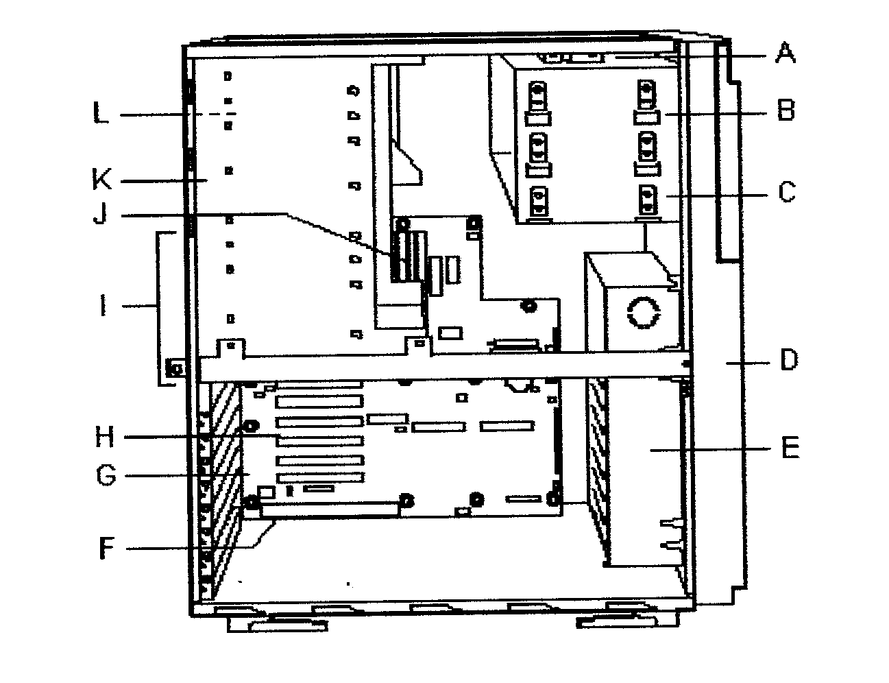
- INTERIOR

-
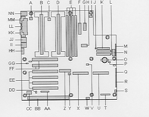
SYSTEM BOARD: Connector and component location.

- PROCESSORS AND MEMORY
Processors
Each Pentium II processor is packaged in a Single Edge Contact (SEC) cartridge. The
cartridge includes the processor core with an integrated 16 KB primary (L1) cache, the
secondary (L2) cache, a thermal plate, and a back cover.
The processor implements the MMX technology and maintains full backward compatibility
with the 8086, 80286, Intel386 TM, Intel486 TM, Pentium, Pentium Pro, and Pentium II
processors. The processor’s numeric coprocessor significantly increases the speed of
floating-point operations and complies with ANSI / IEEE standard 754-1985.
Each processor connects to the system board through a 242-pin edge connector. A
retention module attached to the system board secures the cartridge. Depending on
configuration, your system may have one or two processors.
The processor external interface is multi-processor (MP) ready and operates at 100 MHz.
The processor contains a local APIC section for interrupt handling in MP and uni-processor
(UP) environments.
The second-level cache is located on the substrate of the SEC cartridge. The cache
includes burst pipelined synchronous static RAM (BSRAM). the
Memory
The system board supports only 100 MHz SDRAM. Memory is partitioned as four
banks of SDRAM DIMMS, each providing 72 bits of non-interleaved memory (64-bit
main memory plus ECC).
The controller automatically detects, sizes, and initializes the memory array,
depending on the type, size, and speed of the installed DIMMs, and reports memory size and
allocation to the system through configuration registers.
The system board supports from 32 MB to 2 GB of memory added in order from Slot 1 to Slot
4. Various combinations of 64, 128, 256, and 512 MB DIMMs are supported. The following
table shows a sample of size combinations.
| Bank 0 (J1) |
Bank 1 (J2) |
Bank 2 (J3) |
Bank 3 (J4) |
Total Memory |
| 64 |
|
|
|
64 MB |
| 64 |
128 |
|
|
192 MB |
| 128 |
128 |
128 |
|
384 MB |
| 128 |
128 |
256 |
256 |
768 MB |
| 256 |
256 |
256 |
256 |
1 GB |
| 512 |
512 |
512 |
512 |
2 GB |
9. SECURITY FEATURES
9.1. Mechanical Locks and Monitoring
If installed on your server, the chassis intrusion alarm switch can be activated.
When the side door is opened, the switch transmits an alarm signal to the system
board where server management software processes the signal. The system can
be configured to respond to an intrusion by powering down or locking the keyboard,
for example.
9.2. Software Locks
The BIOS Setup Utility and the SSU provide a number of security features to prevent
unauthorized or accidental access to the system. Once the security measures are enabled,
access to the system is permitted only after the user enters the correct password(s). For
more information on the BIOS Setup Utility and the SSU, refer to Chapter 4.
9.2.1 Passwords
If only a user password, or only an administrator password, is defined and enabled, the
user password or administrator password is entered to boot the system, run BIOS Setup or
the SSU, and exit Secure Mode.
If both a user and an administrator password are defined and enabled, the following takes
effect:
-Either of the passwords is entered to boot the server, enable the keyboard
and mouse, and exit Secure Mode.
-The administrator password must be entered to run the BIOS Setup Utility
or the SSU, and thus gain access to all of the system configuration options.
9.2.2. Secure Mode
The SSU is used to configure and enable Secure Mode. When Secure Mode is in effect:
-The system boots and the operating system loads, but the user password
must be entered to use the keyboard or mouse.
-The system can not be reset or powered down from the front panel
switches.
Secure Mode has no effect on power control via the RTC or on functions enabled via the
Server Manager Module (SMM).
Taking the system out of Secure Mode does not change the state of system power. That is,
if the push-button power switch on the front panel is pressed and released while Secure
Mode is in effect, the system does not power off if Secure Mode is later removed. However,
if the push-button power switch remains depressed while Secure Mode is removed, the system
is powered off.
9.3 Summary of Software Security Features
The following table lists the software security features and describes the
protection each offers. In general, to define and/or enable the features listed here, the
Security Subsystem Group menu of the SSU is used.
| Feature |
Description |
| Secure Mode |
Setting and enabling passwords
automatically places the system in Secure Mode. If a Hot Key combination is defoned
through BIOS Setup or the SSU, the system is placed in Secure Mode the hot-key combination
is pressed. The inactivity timeout period does not have to expire before Secure Mode takes
effect.
When in Secure Mode, the system can boot and load the operating system, but it does not
accept keyboard or mouse input until the correct password is entered.
At boot time, if a CD-ROM is detected in the CD-ROM drive or a diskette is detected in
drive A, the system prompts or a password.
When the password is entered correctly, the system boots from the CD-ROM or diskette and
disables Secure Mode. At boot time, if no CD-ROM is detected in the CD-ROM drive or no
diskette is detected in drive A, the system boots from drive C and automatically enters
Secure Mode. All enabled Secure Mode features go into effect at boot time.
Secure Mode is exited by entering the correct password. |
| Disable writing to diskette |
When this option is enabled and
Secure Mode is active, the correct password must be entered to permit diskette writes.
This option is enabled in the SSU.
The BIOS Setup Utility is used to prevent diskette writes regardless of the
active/inactive status of Secure Mode. |
| Disable the power button |
When this option is enabled and
Secure Mode is active, the power button is disabled. This option is enabled in the SSU. |
| Time-out period for keyboard
& mouse |
When this option is enabled, it
counts an inactivity timeout period that can be from 1 to 120 minutes in duration, as
specified. If no nput and videokeyboard or mouse activity occurs for the specified period,
the blankingsystem does not accept mouse and keyboard input. It blanks the video screen
and write-protects the diskette drive if Secure Mode is active. A password is required to
unlock the system. |
| Administrator |
This option controls access to
BIOS Setup and the SSU. |
Password on boot
(user password) |
The option requires a password to
be entered before the system boots. The system remains in Secure Mode until the password
is entered. Password on boot takes precedence over Secure Mode boot. |
| Boot without keyboard |
This option, set in BIOS Setup,
causes the BIOS to automatically detect and test the keyboard if it is present, and
afterwards display a message. The system can boot without a keyboard. There is no option
in the SSU to enable or display a keyboard. |
| Specify the boot |
This option, set in the SSU,
determines the boot order. If a Secure Mode is enabled (a user password is defined), the
system prompts for a password before it boots completely. If Secure Mode and Secure Mode
boot are enabled, the system boots completely, but does not allow input until a password
is entered. |


