FECO COMMS # 50
 |
FECO:
|
COMMS
# 50 |
|
MODIFICATION
NO:
|
N/A |
|
PRODUCT:
|
3
COM SUPERSTACK II 1100 SWITCH |
|
SUB-ASSEMBLY:
|
N/A |
|
ESTIMATED
MAN HOURS:
|
N/A |
|
CLASS
OF CHANGE:
|
INFORMATIONAL |
|
REASON
FOR CHANGE:
|
INTRODUCTION
OF NEW PRODUCT |
|
RELATED
FECO/AB
|
N/A |
INTRODUCTION OF THE 3 COM SUPERSTACK
II 1100 SWITCH
1.INTRODUCTION
This is to introduce the 3COM SUPERSTACK 11 1100 Switch.
Throughout this FECO a SPACE in a string is shown by a Ñ.
All other spaces are purely cosmetic.
FEATURES:-
-12. 2 or 24 Ethernet 10 base- T ports
-Two fast Ethernet auto-negotiating
- 100 Base-T/10 Base-T ports
- Matrix port for interconnecting 1100/300 Switches in to a single stack
- Two units can be connected 'back to back' using a matrix cable.
- Up to 4 units can be connected together using a matrix module.
- A slot for an expansion module or matrix module.
- A slot for an optional transceiver (10MBps) (Disables port 1 if installed)
- External Redundant PSU or UPS
- 19" RACK mounted or stand alone.
3. APPLICATION
Due to increased functionality, Client Server software products released during the
last few years have used increasing amounts of network bandwidth.
To maintain performance, new standards have been developed providing 100MBps and
Gigabit bandwidths.
These increased bandwidths are suitable for 'backbones' or for 'power users'. They are
incompatible with 10MBps network devices and not appropriate for most users.
The challenge is to 'switch' down this bandwidth providing appropriate speeds to
different users/subnets. The device which has been developed to do this is called a
switch.
The 1100 switch has two 10/100 auto negotiating ports for connections to backbones,
servers or other switches and 12 or 24 10 base-T ports for connections to Hubs, other
switches, desktops, servers or terminal servers.
As switches also pass packets at 'wire speed', they are being used to replace Hubs.
(Hubs usually store and forward packets which impacts on performance.)
4. DIMENSIONS/ENVIRONMENTAL REQUIREMENTS
Height: 76mm (3.0in) x Width: 483mm (19.0in) x Depth: 300mm (12.0in)
Operating Temperature 0 deg to 50 deg C (32 deg F to 122 deg F)
Operating Humidity 10 to 95% relative humidity non-condensing
Heat Dissipation 117 watts, (400BTU/hour)
Power Requirements 50/60Hz
90-240VAC
3 amps (max)
5. MEC IDENTITY
The mec identity is:-
S/STACK 2 - SWITCH - 1100-24P
6. SWITCH 1100- FRONT VIEW DETAIL
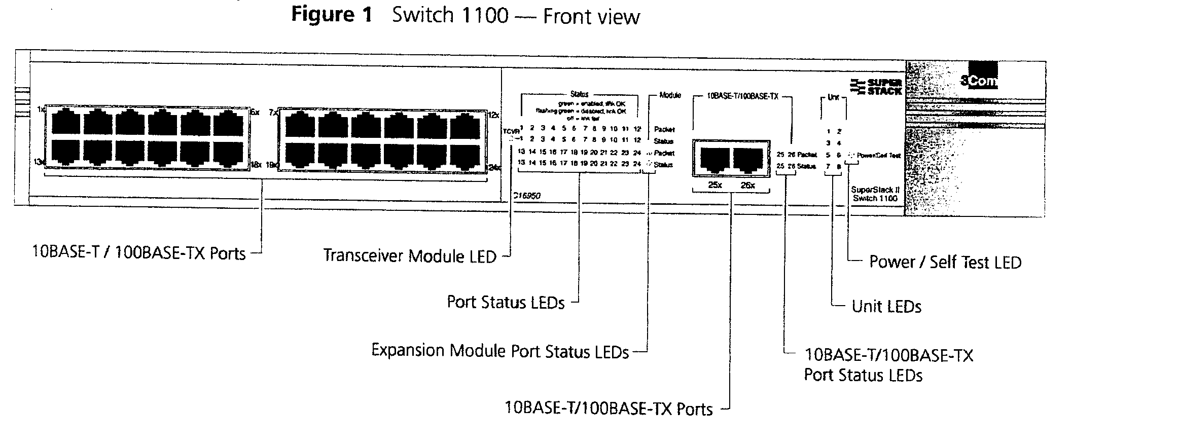
Port Connections 10BASE-T Ports
The Switch has 12 or 24 10BASE-T ports configured as MDIX (cross-over).
The maximum segment length is 100m (328ft) over Category 5 twisted pair cable.
As these ports are configured as MDIX (cross-over), you need to use a cross-over cable
to connect to devices whose ports are MDIX-only.
Port Connections 10BASE-T/100 BASE-TX PORTS
The Switch has two auto-negotiating 10BASE-T/100BASE-TX ports configured as MDIX
(cross-over). These ports can be set to 10BASE-T half duplex, 10BASE-T full duplex,
100BASE-TX half duplex, 100BASE-TX full duplex, or they can automatically detect the speed
and duplex mode of a link and provide the appropriate connection. The maximum segment
length is 100m (328ft) over Category 5 twisted pair cable.
As these ports are configured as MDIX (cross-over), you need to use a cross-over cable
to connect to devices whose ports are MDIX-only.
LEDs Table 3 lists the LEDs visible on the front of the Switch, and their states
according to colour.
Table 3 LED behaviour
LED Colour Indicates
| TCVR Yellow |
Port 1 is a Transceiver Module fitted to the rear of the Switch. |
| Off |
Port 1 is operating as a 10BASE- T port. |
Port Status LEDs
| Packet Yellow |
Packets are being transmitted/received on the port. |
| Off |
No packets are being transmitted/received on the port. |
| Status Green |
A link is present, and the port is enabled. |
| Green flashing |
A link is present, but the port is disabled. |
| Off |
No link is present. |
Expansion Module Port Status LEDs
| Packet Yellow |
Packets are being transmitted/received on the expansion |
Module or Matrix Module port (s).
| Off |
No packets are being transmitted/received on the expansion |
Module or Matrix Module port(s).
| Status Yellow |
A valid Expansion Module or Matrix Module is installed. |
| Yellow flashing |
An unrecognized Expansion Module or Matrix Module is installed. |
| Off |
No expansion Module or Matrix Module is installed. |
Unit LEDs
| 1-8 Green |
The Switch forms a stack with other Switch 1100/Switch |
| 3300 units; |
the LED indicates the position of the Switch in the stack and that a link is present.
Note that although there are eight LEDs, only four Switch units can be stacked at present. |
| Off |
The Switch is stand-alone. |
| Power/Self |
Test LED |
| Green |
The Switch is powered-up. |
| Green flashing |
The Switch is either downloading software or is initializing (which includes running a
Power On Self Test) |
| Yellow |
The Switch has failed its Power On Self Test. |
| Off |
The Switch is not receiving power. |
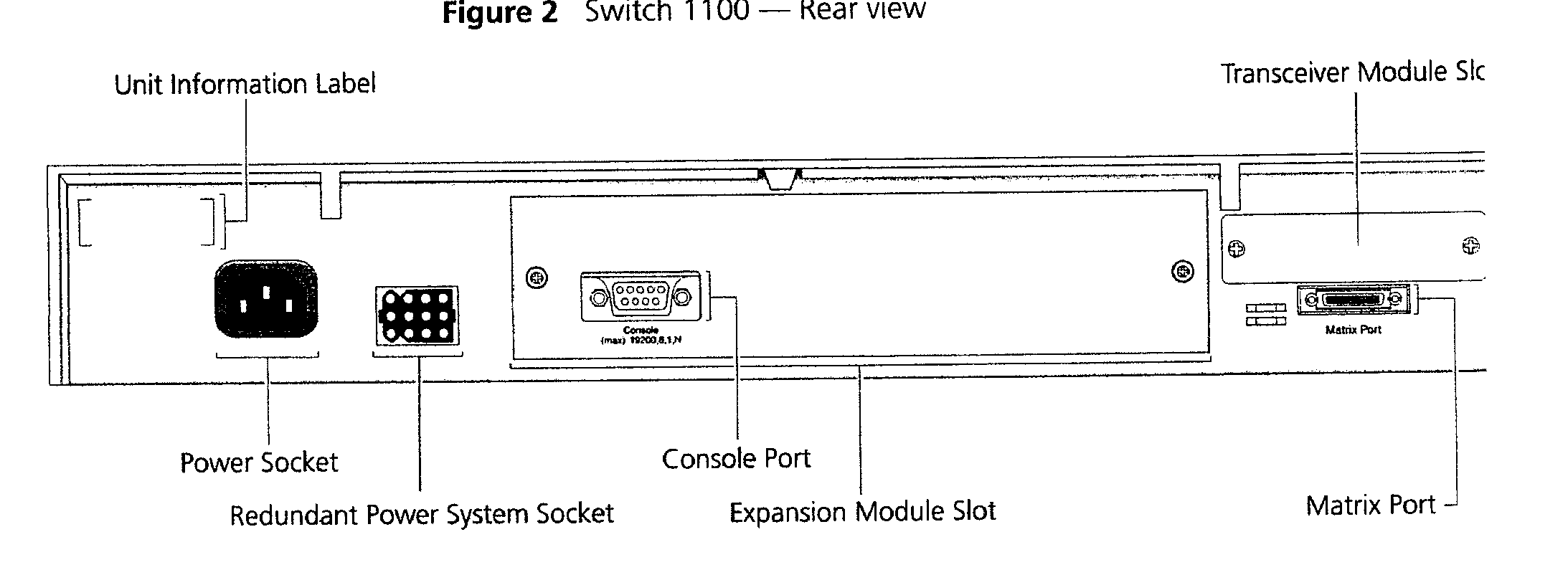
7. Switch 1100 - REAR VIEW DETAIL
Unit Information Label This label shows the following:
- The 3Com product name of the Switch
- The 3Com 3C number of the Switch
- The unique MAC address (Ethernet address) of the Switch
- The serial number of the Switch
You may need this information for fault reporting purposes.
Power Socket
The Switch automatically adjusts its power setting to any supply voltage in the
range 90-240V A.C.
Redundant Power System Socket
To protect against internal power supply failure, you can use this socket to
connect a SuperStack II
Advanced Redundant Power System (RPS) to the Switch. See the manual for full details.
Console Port
The console port allows you to connect a terminal and perform remote local
out-of-band management. The console port uses standard null modem cable and is set to
auto-baud, 8 data bits, no parity and 1 stop bit.
Expansion Module Slot
You can use this slot to install an Expansion Module that provides a high-speed
link to the rest of your network, or a Matrix Module that provides four matrix ports for
stacking Switch units together. 3 Com provides a range of Expansion Modules.
When an Expansion Module or Matrix Module is not installed, ensure the blanking plate
is secured in place.
Transceiver Module Slot
You can use this slot to install a Transceiver Module. When a Transceiver Module is
installed, the Transceiver Module port becomes port 1 and the port labelled 1 on the front
panel becomes inactive. The Transceiver Module can provide a 10Mbps Ethernet half duplex
link to the rest of your network using various media such as fiber and coaxial cabling.
When a Transceiver Module is not installed, ensure the blanking plate is secured in
place.
Matrix Port
The matrix port allows you to:
- Stack the Switch with another Switch 1100 or Switch 3300 unit using a single Matrix
Cable.
- Stack the Switch with up to three other Switch 1100 or Switch 3300 units, if one of the
units has a Matrix Module installed.
8. CABLING RJ45 PIN ASSIGNMENT
To connect to Terminal Servers, Desktops and Servers use a midi cable (straight
through)
To connect to Hubs or other switches use a midi x cable (cross over)
All cabling must be FTP Cat 5 cable with the screen connected to the head shell at both
ends.
MIDI CABLE
END A END B
| Signal |
Pin |
Colour |
Pin |
Signal |
| Txdata+ |
1 |
White/Orange |
1 |
Txdata+ |
| Txdata- |
2 |
Orange/White |
2 |
Txdata- |
| Rxdata+ |
3 |
White/Green |
3 |
Rxdata+ |
| N/A |
4 |
Blue/White |
4 |
N/A |
| N/A |
5 |
White/Blue |
5 |
N/A |
| Rxdata- |
6 |
Green/White |
6 |
Rxdata- |
| N/A |
7 |
White/Brown |
7 |
N/A |
| N/A |
8 |
Brown/White |
8 |
N/A |
MIDIx CABLE
ENDA ENDB
| Signal |
Pin |
Colour |
Pin |
Signal |
| Rxdata+ |
1 |
White/Green |
3 |
Txdata+ |
| Rxdata- |
2 |
Green/White |
6 |
Txdata- |
| Txdata + |
3 |
White/Orange |
1 |
Rxdata+ |
| N/A |
4 |
Blue/White |
4 |
N/A |
| N/A |
5 |
White/Blue |
5 |
N/A |
| Txdata- |
6 |
Orange/White |
2 |
Rxdata- |
| N/A |
7 |
White/Brown |
7 |
N/A |
| N/A |
8 |
Brown/White |
8 |
N/A |
Console to VDU Cable
9. CONFIGURATION VALID TOPOLOGIES
Network Configuration Examples
The following illustrations show some examples of how the Switch can be placed on
your network.
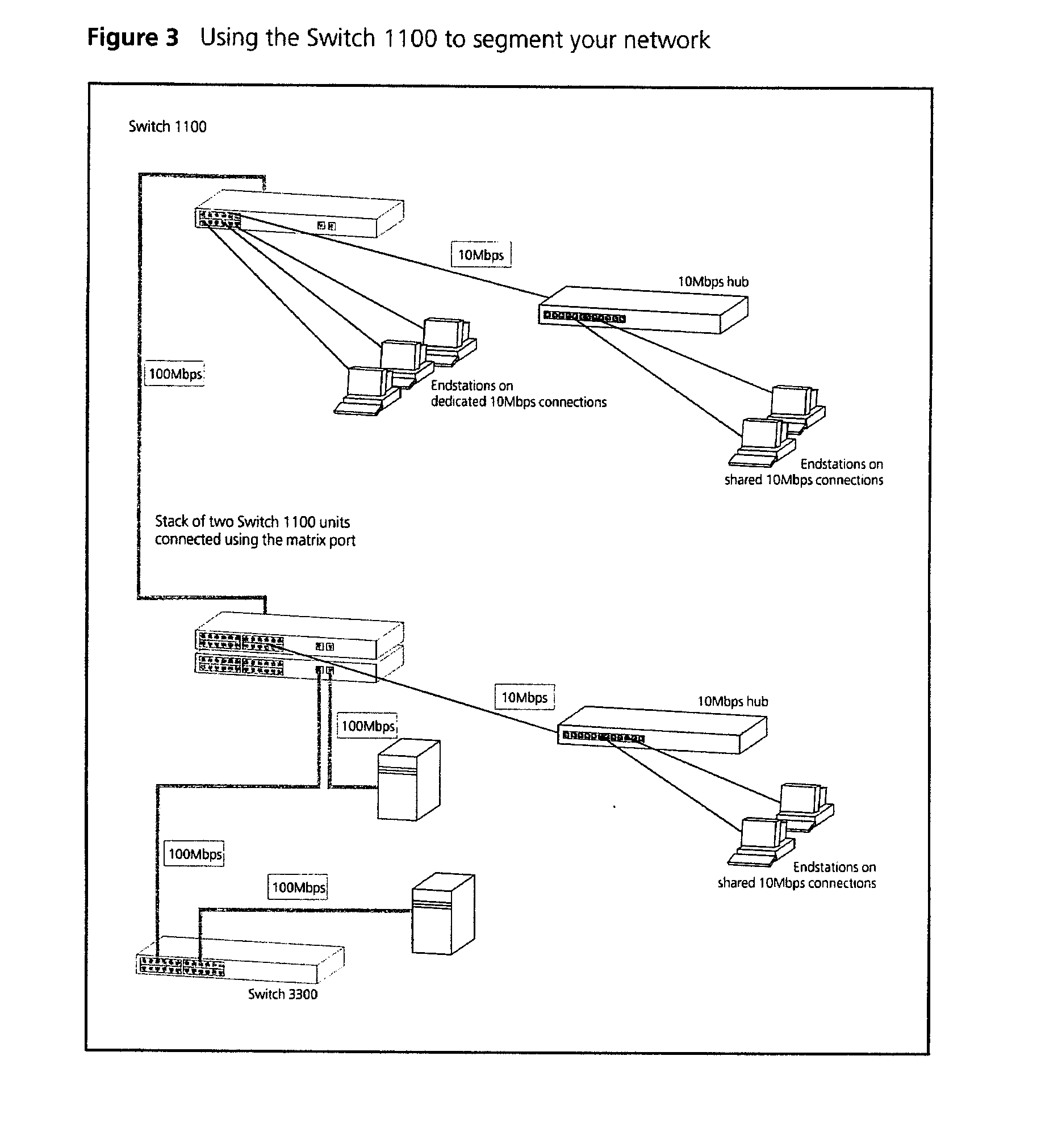
Network Segmentation I
Figure 3 shows how the Switch 1100 fits into a large corporate network with a Fast
Ethernet infrastructure. A Switch is positioned on each floor and servers are centralized
in the basement.
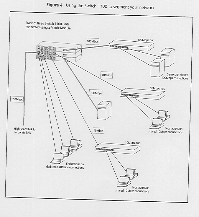
Network Segmentation II
Figure 4 shows the Switch 1100 in a second workgroup situation. This setup could be
that of a small office within a large corporation, or part of a larger corporate network.
Most of the switch ports have multiple endstations.
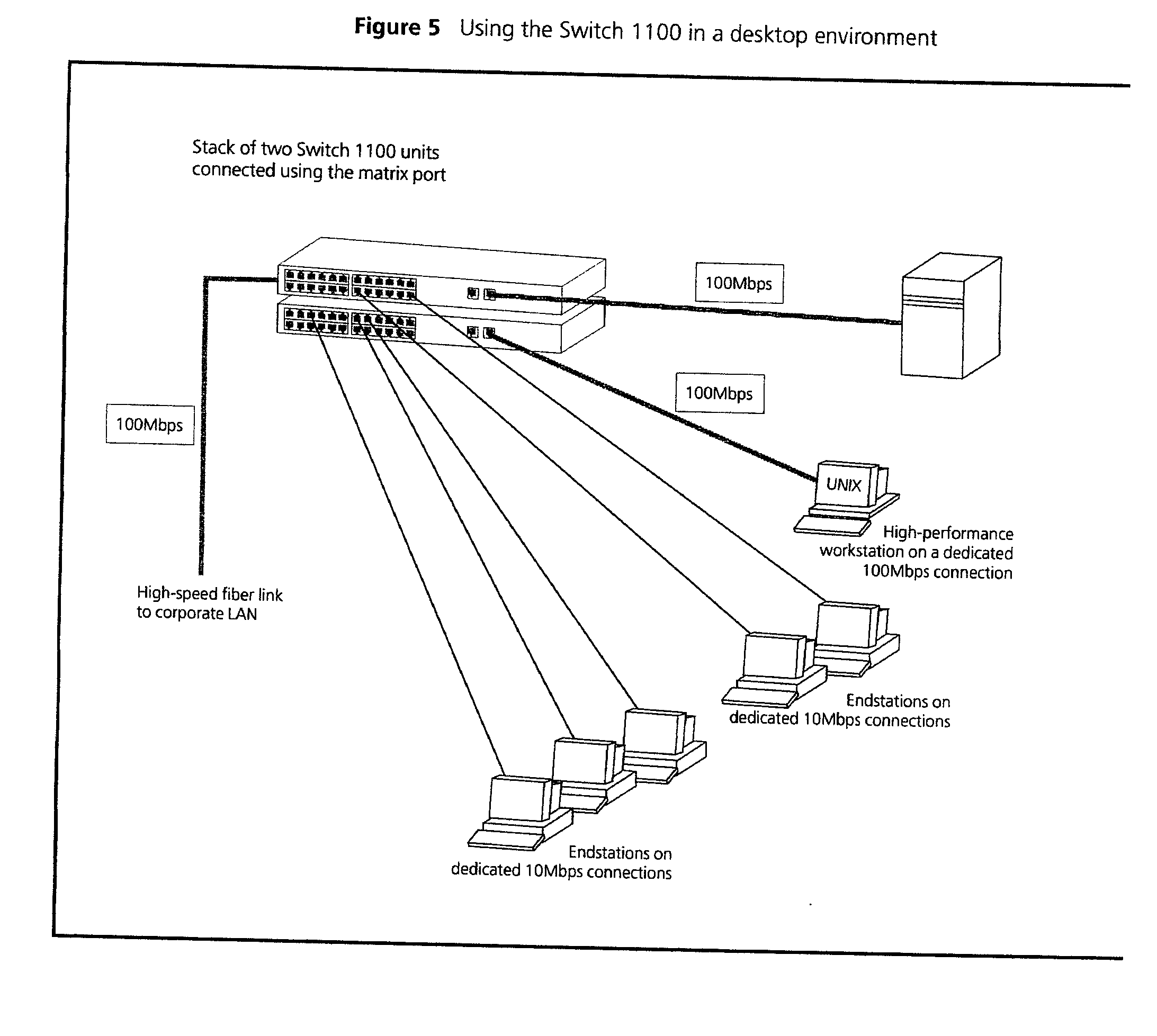
Desktop Switching
Figure 5 shows the Switch 1100 used for a group of users in a large corporate
network. Here switching is brought to the desktop with a single endstation per port. Local
servers are connected via 100Mbps Fast Ethernet links.
Configuration Rules for Fast Ethernet
The topology rules for 100Mbps Fast Ethernet are slightly different to those for
10Mbps Ethernet. Figure 6 illustrates the key topology rules and provides examples of how
they allow for large-scale Fast Ethernet networks.
 The key topology
rules are:
- Maximum UTP cable length is 100m (328ft) over Category 5 cable.
- A 412m (1352ft) fibre run is allowed for connecting switch-to-switch or
endstation-to-switch, using half-duplex 100BASE-FX.
- A total network span of 325m (1066ft) is allowed in single-repeater topologies (one hub
stack per wiring closet with a fibre run to the collapsed backbone); for example, a 225m
(738ft) fibre link form a repeater to a router or switch, plus a 100m (328ft) UTP link
from a repeater out to the endstations.
Configuration Rules with Full Duplex
The Switch provides full duplex support for all its fixed ports, including
Expansion Module ports. Full duplex allows packets to be transmitted and received
simultaneously and, in effect, doubles the potential throughput of a link.
With full duplex, the Ethernet topology rules are the same, but the Fast Ethernet rules
are:
- Maximum UTP cable length is 100m (328ft) over Category 5 cable.
- A 2km (6562ft) fibre link is allowed for connecting switch-to-switch, or
endstation-to-switch.
10. CONFIGURATION SET UP
Switches such as the 3 Com SuperStack II 1100 are layer 2 switches. This means they
operate at the MAC (media access control) address level. (The node still needs an IP
address). Basically this means that the switch 'learns' which device(s) is connected to
which of it's ports. It stores this information in a volatile table as a list of Mac
address to port. The limitation this does impose is that there is no performance gain by
connecting two channels to the same subnet. Rather than doubling the effective bandwidth,
the 'Spanning Tree' protocol will actually detect that there are two paths and disable one
of them. (This is to prevent duplicate frames and storms).
What this configuration can provide, however, is a measure of resilience. If the active
link fails, then the 'Spanning Tree' protocol will enable the other link.
The 3 Com SuperStack II 110 switch supports various setup methodologies.
For simplicity, it is recommended that the command line interface is adopted as the
standard.
The only parameters that require changing from the defaults are:-
a) IP address
b) Subnet mask
c) Default gateway (if applicable)
Command line setup utilities can be accessed either through the console port, (initial
setup) or via telnet, if a valid IP address has been previously configured.
Attach a VDU configured for:-
19200, 8, N, 1, xoff/xon
to the console port, using a 9 pin to 25 pin null modem cable. (See cable specification
earlier in this document).
Power up the VDU and the switch 1100
A switch 1100 generated login prompt will be displayed.
To log in to the command line Configuration Utility enter at the prompt
admin <CR>
At the password prompt enter <CR>
The top level command line interface will be displayed.
To configure an IP address, subnet mask and default gateway enter:-
ip Ñ interfaceÑ define
The following prompt will be displayed allowing you to enter an IP address for the
switch:-
Enter IP address (0. 0. 0. 0)
Enter a valid IP address
The following prompt is displayed allowing you to enter a subnet mask for the switch:-
Enter subnet mask (0. 0. 0. 0)
Enter a valid subnet mask for the switch
The following prompt will be displayed:-
Enter default gateway (0. 0. 0. 0)
Enter the IP address of the default gateway, if applicable.
The system will prompt for a SLIP address
<CR> through this
The IP address, subnet mask and default gateway have now been configured.
To display IP information, enter
ip Ñ interfaceÑdisplay
11. TESTING
11.1 To test the switch:-
(a) Using FTP cable of the correct pin configurations, connect devices to the switch
1100 as specified in the Project Plan.
(b) Use ping to test the connection to the switch and other devices.
12. TROUBLE SHOOTING
The switch maintains statistical information about its performance. To display this
information to assist with problem diagnosis:-
At the Top-level menu, enter:-
Ethernet statistics
The following prompt is displayed:-
Select Ethernet port (1-24)
Enter the number of a port.
The statistical information for the port is displayed as follows:-
Port: 1 Port Speed: 10Mbps HD Auto
Received Stats Transmit Stats
Unicast Packets: 0 Unicast Packets: 50
Non Unicast Packets: 0 Non Unicast Packets 18734
Octets: 0 Octets: 1397087
Fragments: 0 Collisions: 0
Errors
Undersize: 0 Oversize: 0
CRC Errors: 0 Jabbers: 0
Packet Size Analysis
64 Octets: 13752 256 to 511 Octets: 5
65 to 127 Octets: 4404 512 to 1023 Octets: 0
128 to 255 Octets: 623 1024 to 1518 Octets: 00
The following statistical information is displayed:-
Received Stats
-
Unicast Packets - Displays the number of packets with a single destination address
that have been successfully received by the port.
-
Non Unicast Packets - Displays the number of packets with a multicast or broadcast
destination address that have been received by the port.
-
Octets - Displays the number of Octets (8 bit units) that have been received by the
port. The octects calculation includes the MAC header and the Cyclical Redundancy Check
(CRC), but excludes the preamble/Start-of-Frame Delimiter.
-
Fragments - Displays the number of incomplete packets that have been received by the
port; that is, the number of packets that:
- Did not contain a whole number of octets, or had a bad Frame Check Sequence (FCS)
- Contained less than 64 octets (including FCS octets, but excluding framing bits).
Transmitted Stats
-
Unicast Packets - Displays the number of packets with a single destination address
that have been transmitted by the port.
-
Non Unicast Packets - Displays the number of packets with a multicast or broadcast
destination address that have been successfully transmitted by the port.
-
Octets - Displays the number of octets that have been transmitted by the port.
-
Collisions - Displays an estimate of the total number of collisions that have
occurred when the port was transmitting.
Errors
-
Undersize - Displays the number of packets seen by the port that were smaller than
the minimum size defined for IEEE 802.3 packets. Undersize packets may indicate externally
generated interference causing problems on your network. Check your cabling routes, and
re-route any cabling that may be affected by external sources.
-
CRC Errors - Displays the number of packets seen by the port that contained a CRC
error or an alignment error. A CRC error occurs if a packet of legal length has an invalid
CRC but does not have a framing error. An alignment error occurs if a packet has a CRC
error and does not contain a whole number of octets.
CRC and alignment errors may be caused by faults in transmitting devices. Change the
Network Interface Card (NIC) of the device connected to the port.
If this does not solve the problem, check your cables and connections for damage.
-
Oversize - Displays the total number of packets seen by the port that exceed the
maximum length defined for IEEE 802.3 packets. If you see a high number of oversize
packets on your network, you need to isolate the source of these packets and examine the
Network Interface Card of the device. Note that some protocols may generate oversize
packets.
-
Jabbers - Displays the total number of packets received on the port that were longer
than 8000 octets (but including FCS octets, but excluding framing bits). Jabber is caused
by faulty devices transmitting oversize packets continuously.
Packet Size Analysis
Displays the number of packets seen by the port that had a length which was in one
of six ranges between 64 and 1518 octets. This information may help you to analyse the
efficiency of your network layer protocol.
Displaying Port Summary Information
You can display summary information about Ethernet ports on the Switch using the summary
on the Ethernet menu.
To display the port summary information:-
1. At the Top-level menu, enter:
ethernet summary
The following prompt is displayed:-
Select Ethernet port (1-24,all):
2. Enter the number of a port, or enter all for all the ports.
The port summary information for the port(s) is displayed.
An example of the port summary information is shown below:-
| Port |
State |
Rx Packets |
Rx Octets |
Errors |
| 1 |
Enabled |
163542 |
65439864 |
4 |
| 2 |
Disabled |
0 |
0 |
0 |
| 3 |
Enabled |
639263 |
83636219 |
4 |
| 24 |
Enabled |
645232 |
23142514 |
0 |
The statistics that are displayed are gathered in the time interval since the last
reset, initialisation or power-off/on cycle.
Return
to Index


 The key topology
rules are: