COMMS # 67
 |
FECO:
|
COMMS
# 67 |
|
MODIFICATION NO:
|
N/A |
|
PRODUCT:
|
MULTITECH
MT5600 ZDXe MODEM |
|
SUB-ASSEMBLY:
|
N/A |
|
ESTIMATED MAN HOURS:
|
N/A |
|
CLASS OF CHANGE:
|
MANDATORY |
|
REASON FOR CHANGE:
|
INTRODUCTION
OF NEW DIAGNOSTIC MODEM |
|
RELATED FECO/AB
|
N/A |
MULTITECH MT5600 ZDXe DIAGNOSTIC MODEM
1 NOTE:
Throughout
this FECO a SPACE in a string is shown by a Ñ .
All
other spaces are purely cosmetic
2 INTRODUCTION
This
is to introduce the new diagnostic modem the Multitech MT5600 ZDXe.
This
modem is a direct replacement for the previous diagnostic modem the US Robotics.
3 DESCRIPTION
The unit is compact and neat, and uses standard
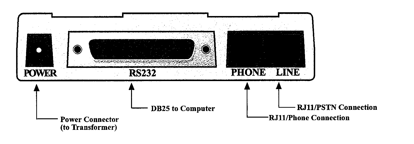
DB25 connectors, see below. There is an
external
power supply.
4 FRONT VIEW

5 REAR VIEW

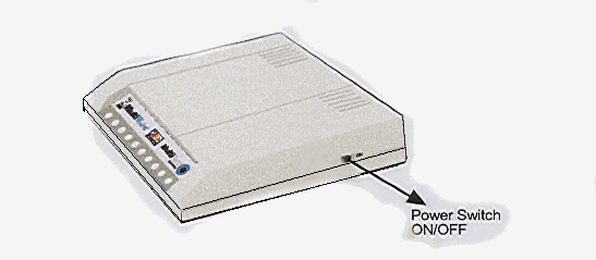
6 COMPLETE VIEW

7 EDP
SPECIFICATION
7.1 Data compression
V.42bis, (4:1throughput)or MNP 5 (2:1 throughput) data
compression.
7.2 Speed Conversion
Serial port data rates adjustable to 300, 1200, 2400, 4800,
9600, 19,200, 38,400, 57,600
and 115,200 bps.
7.3 Flow Control Options
Xon/Xoff, Hardware RTS/CTS.
7.4 Mode of Operation
Full duplex over dial-up lines.
7.5 Intelligent Features
Automatic or manual dialing, Automatic or manual answer, Microprocessor-
controlled,
EIA extended Automode, adaptive line probing, automatic symbol rate
and carrier
frequency during start-up, retrain and rate renegotiation, Autodial,
Redial,
Tone dial, Dial pauses, Call status display, Auto-parity and data rate
selection,
Keyboard-controlled modem options, Nonvolatile memory and on-screen
displays
for modem option parameters and four telephone numbers/command lines
of up to 40
digits each
7.6 Command Buffer
40 characters
7.7 Data Modulation
Trellis Coded Modulation (TCM) at K56flex, 33,600, 31,200
28,800, 26,400, 24,000, 21,600,
19,200, 16,800, 14,400, 12,000 and 9600bps,
Quadrature
Amplitude Modulation (QAM) at 9600 (non-trellis), 4800 and 2400
bps, PSK at
1200 bps, FSK at 300 bps.
7.8 Data Carrier Frequencies
1800Hz
V.32/V.32bis/V.32terbo/Enhanced V.34/K56flex.
K56flex
speeds plus 33.6K, 31.2K, 28.8K, 26.4K, 24K,
21.6K,
19.2K, 16.8K, 14.4K, 12K, 9.6K, 7.2K,4.8K,2.4K,1.2k, and 0-300bps.
7.9 Carrier Frequencies 2400 & 1200bps
(V.22bis/V.22 or Bell 212A Standard)
Transmit Originate: 1200 Hz
Transmit Answer: 2400 Hz
Receive Originate: 2400 Hz
Receive Answer: 1200 Hz
7.10 Carrier Frequencies, 300 bps (Bell Standard)
1270 Hz Mark, 1070 Hz Space for Transmit Originate
2225 Hz Mark, 2025 Hz Space for Receive Originate
2225 Hz Mark, 2025 Hz Space for Transmit Answer
1270 Hz Mark, 1070 Hz Space for Receive Answer
7.11 Carrier Frequencies V.21
980Hz Mark, 1180 Hz Space for Transmit Originate
1650 Hz Mark, 1850 Hz Space for Transmit Answer
1650 Hz Mark, 1850Hz Space for Receive Originate
980 Hz Mark, 1180 Hz Space for Receive Answer
7.12
Carrier Frequencies V.23
390 Hz Mark, 450 Hz Space for Transmit Originate
1300
Hz Mark, 2100 Hz Space for Transmit Answer
1300
Hz Mark, 2100 Hz Space for Receive Originate
390
Hz Mark, 450 Hz Space for Receive Answer
7.13 Transmit Level
-10dBm
(dial-up),
7.14
Frequency Stability
+ 0.01%
7.15
Receiver Sensitivity
-43 dBm under worst case conditions
7.16 AGC Dynamic Range
43dB
7.17 Interface
EIA
RS232C/ITU V.24
7.18 Connectors
One
DB25 RS232C connector; two RJ11 for phone, and dial-up line; &
power
jack.
7.19 Diagnostics
Power-on Self Test, Local Analog Loop, Local Digital Loop, Remote
Digital Loop,
7.20 Indicators
LED’s for Transmit Data, Receive Data, Carrier Detect, Various Speed
Indicators,
Off Hook, Terminal Ready, Error Correction, Fax, and Error.
7.21 Controls
Power
On/Off.
7.22 Speaker
2
inch comne with software or command controlled volume.
7.23 Operating Temperature
0° to 50° C (32° to 120° F)
7.24 Power Requirements
240V/50Hz (International).
7.25 Dimensions
6.150" x 9.00" x 1.375"
15.6cm
x 22.9 cm x 3.5cm
7.26 Weight
8oz.
224 grams.
7.27 Warranty
Ten years
8
MEC
IDENTITY
The
MEC identity is MT-5600ZDXE-MODEM
9
MODEM
SET-UP
9.1 To set the
modem connect an 'H' cable to the serial port and set the VDU to
9600,
8, 1, N.
9.2 Type
in AT&V to display the active profile. Note this if necessary.
9.3 Type
in AT&F to default the modem to factory settings.
9.4 Type
in the following to setup the modem
AT
&E5 &D0 &K5 Q1 E0 &S0 S0 =1 &W
NOTE
These commands contain no spaces.
9.5
Key to commands
AT
= ATTENTION CODE .
&E5
= Xon/Xoff FLOW CONTROL
&D0 = Modem ignores the true status of
the DTR signal and responds as if it
is
always on.
&K5
= Enable transparent Xon/Xoff Flow Control.
Q1
= Disable results codes.
E0
= Do not echo keyboard characters to the
computer.
&S0
= Force DSR on at all times.
S0=1
= Enable auto answer.
&W
= Store current modem settings in NVRAM as profile
&V
= To display active profile
10 SERVICING
Servicing
is by replacement.
11 DIAGNOSTICS
For full details see the Troubleshooting Section of the Manual.
AT&T0
Abort any test
AT&T1
Local Analogue Loopback Test / V.54 Loop3
AT&T3
Digital Loopback Test / V.54 Loop2(Local/Manual)
ATO0
To stay On-Line after test
ATH0
Terminate call
AT&T6
Digital Loopback Test / V.54 Loop2 (Remote/Automatic)
12 MODEM
CONNECTIONS
SERIAL PORT
CONNECTIONS identical to previous diagnostic modems.
Use
standard EDP Cable Specifications.
25 pin D Type Male
1 FRAME
GROUND
2 TD
3 RD
4 RTS
5 CTS
6 DSR
7 SG
8 CD
11 SSD
20 DTR
Return to
Index


