IO # 11
 |
FECO:
|
IO
# 11 |
|
MODIFICATION
NO:
|
N/A |
|
PRODUCT:
|
SPECIALIX
RIO LDM |
|
SUB-ASSEMBLY:
|
N/A |
|
ESTIMATED
MAN HOURS:
|
N/A |
|
CLASS
OF CHANGE:
|
MANDATORY |
|
REASON
FOR CHANGE:
|
LISTING
SETUP FOR RIO LDM |
|
RELATED
FECO/AB
|
AB
169 |
RIO LDM (Long Distance Module)
1 The RIO Long
Distance Module (LDM) enables the extension of the RIO system via cable leased line or the
telecommunications system.
Connections can be made over thousands of miles using synchronous (X.21/X.21bis) or
asynchronous (RS232/RS422)
modems.
2 The LDM is
specifically designed for use on high-speed synchronous connections. Slower, asynchronous
speeds are
supported
but are only recommended for applications where low throughput is acceptable.
3 The LDM consists of
two Long Distance Units (LDUs). One LDU connects your local host card or RTA to a Comms
unit, the
other connects the remote RTA to a Comms unit.
The
speed and protocol are configured using a dial on the LDU. The Comms unit can be a modem
or Line Driver, or
more likely
with EDP customers a Kilostream NTU.
The LDM
also supports a twisted-pair RS422 cable up to a distance of 1 km
4 RIO LDM
CONNECTION
Line
Driver/Modem/NTU
4.1

Line
Driver/Modem/NTU
5 RIO Long
Distance Unit (LDU)
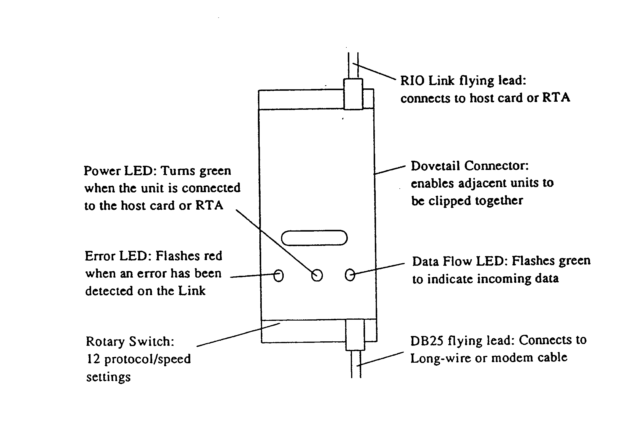
5.1 The LDU consists of a
converter box with two flying leads (see below). One is a metre-long RIO Link cable which
plugs
into your host card or RTA; the other is a serial cable with a DB25 connector which
connects to yourComms
unit
or RS422 long-wire cable.
5.2

6 Installing an
LDM Connection
6.1 Synchronous X21 connection for
Kilostream connection, connect the LDU to the NTU by means of a cable Type FK
6.2 Asynchronous Long Wire
Connection use cable type LM
6.3 Modem Connection for modem
connection use cable type LN
6.4 Using a small screwdriver, set
the rotary switch on each LDU to the required EDP setting:
7 for Long Wire A for Kilostream.
Switch
Line Speed Transmission Connection
0 9600
Asynchronous Modem
1 19200
Asynchronous Modem
2
38400 Asynchronous Modem
3
RESERVED - -
4
RESERVED - -
5
78000 Asynchronous Long-wire
6
156250 Asynchronous Long-wire
7
312500 Asynchronous Long-wire
8
Ext Rx, Ext Tx Clk* Synchronous Modem
9
Ext Rx/Tx Clock* Synchronous X21bis
A
Ext Rx/Tx Clock** Synchronous X21
B
RESERVED - -
C
9600 Asynchronous Modem/Autodial
D
19200 Asynchronous Modem/Autodial
E
38400 Asynchronous Modem/Autodail
F
RESERVED - -
*Transmit and receive clocks are separate inputs.
**One clock input provides both transmit and receive clocks.
6.5 Notes
- Switches 3,4,B and F must not be selected.
- For an Asynchronous modem, select switch setting 0,1 or 2. Select the fastest speed
setting (2), unless operating in a noisy environment where a slower speed is advisable.
- For synchronous modems, select switch setting 8.
- If you are connecting the LDM to ISDN Terminal Adaptors, choose switch setting 9 or A
(depending on your installation).
6.6
- Speeds below 14.4 Kbit/s are not supported.
- Modems should be configured to 8 data bits.
- Flow control must be disabled
- Command echo must be disabled
- Display of results codes must be suppressed.
6.7 For Asynchronous modes:
- Modems must support a minimum of V32bits
- Modems must connect at a minimum speed of 9600 baud
- Modems should be set to 8 data bits, 1 stop bit and no parity
- Hardware flow control must be enabled
- Command echo must be disabled
- Display of result codes must be suppressed.
6.8 When the units (host Card/RTAs) at each
end of the LDM connection are powered up, check that the Power LED on
each LDU is green
6.9 When using NTU modems ensure that the NTU
modem is powered on and connected to the LDU before connecting the
LDU to your RIO
system.
6.10 Once a connection has been established, some
Asynchronous modems are able to negotiate a faster line speed on the
telecommunications
link. If you are using such modems, your RTAs will temporaily disconnect and then
reconnect at
the higher speed. This
is, of course, to your advantage, and the fault status messages output to the console by
the RIO
configuration software
can be ignored.
6.11 Terminals logged in when modems are
disconnected or the line dropped will continue where they left off when the line is
reconnected.
7 Cabling
The pinouts of the DB25 connectors on the RS422 flying lead are as follows:
Pin Signal Name Direction
1 Chassis Chassis Ground -
2 TXD Transmit Data Output RS232
3 RXD Receive Data Input RS232
4 RTS* Request To Send Output RS232
5 CTS* Clear To Send Input RS232
6 N/C Not Connected -
7 GND Ground -
8 DCD* Data Carrier Detect Input RS232
9 DCD+ Data Carrier Detect Input RS422
10 RXD- Inverse RXD Input RS422
11 RXD+ Receive Data Input RS422
12 TXD- Inverse TXD Output RS422
13 TXD+ Transmit Data Output RS422
14 CTS- Inverse CTS Input RS422
15 TXC Transmit Clock Input RS422
16 CTS+ Clear To Send Input RS422
17 RXC Receive Clock Input RS422
18 RTS- Inverse RTS Output RS422
19 RTS+ Request To Send Output RS422
20 DTR* Data Terminal Ready Output RS422
21 DCD- Inverse DCD Input RS422
22 DTR+ Data Terminal Ready Output RS422
23 DTR- Inverse DTR Output RS422
24 RXC- Inverse RXC Input RS422
25 RXC+ Receive Clock Input RS422
*Active Low Signals.
7 The
maunfacturer recommends that a maximum of two LDM are fitted to any one host.
Also
that no more than 16 ports are connected remotely via this method,
i.e.
1 x RTA16 or 2 x RTA8. See AB169 for details.
Different
configurations will be encountered in the field.
Return
to Index


