TALLY # 95
 |
FECO: |
TALLY
# 95 |
| MODIFICATION
NO: |
N/A |
|
PRODUCT:
|
TALLY
T9112 LASER PRINTER |
| SUB-ASSEMBLY: |
N/A |
| ESTIMATED
MAN HOURS: |
N/A |
|
CLASS
OF CHANGE:
|
INFORMATIONAL |
| REASON
FOR CHANGE: |
INTRODUCTION
OF NEW PRINTER |
| RELATED
FECO/AB |
N/A |
INTRODUCTION OF THE TALLY T9112 LASER PRINTER
1. INTRODUCTION
This is to introduce the TALLY T9112 Laser Printer. It is a 600 x 600 dpi mono laser
printer producing up to 12 pages per minute. The printer can be used as an office printer
or as a personal printer. The printer is to replace the OKI 400/800 range of printers
which are no longer available.
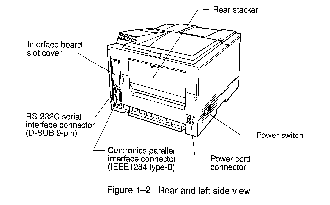
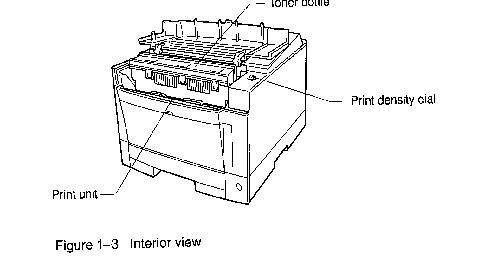
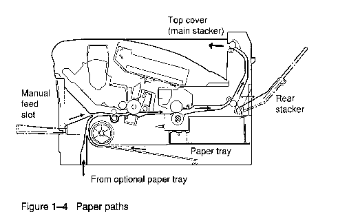
2. VIEWS


3. MEC IDENTITY
The MEC Identity is TALLY-T9112
4. SPECIFICATION
Printer Type T9112 LASER
Processor 75 MHz 64 BIT Risc
Printer life 500,000 pages/5 years
Monthly Workload Up to 35,000 pages per month
Resolution 600 x 600dpi (Up to 4,800 x 600 with EET)
Print speed Up to 12 pages per minute
Emulation's Std - PCL 6 (including PCL5e)
Opt - PostScript Level 11 compatible / IBM / EPSON
Auto Emulation Switching
Memory Std - 4Mb
Opt - 4, 8, 16, 32 Mb
Max - 68 Mb
(2 slots available)
Permanent Storage Area Opt - 4Mb flash SIMM for permanent storage of downloadable forms
and logos etc.
Fonts Std - 1 Bit-map, 114 Scaleable
Opt - 35 Scaleable PostScript level 2 fonts
Opt: Scaleable Bar Code and OCR-A/OCR-B
Paper Handling Input Std - Manual feed & 250 sheet Universal cassette
Opt multi-purpose feeder
(100 sheets or 30 envelopes)
Opt - 500 sheet 2nd Universal cassette
Paper Handling Output Std - Face down 250 sheets
Std - Face up 20 sheets via straight paper path
Paper Sizes A4, Letter, A5, Executive, Legal (separate tray required)
Manual/Multi-purpose Feeder
Min - 100mmx 148mm
Max - 216mm x 356mm
Envelopes COM - 10, Monarch, C5, DL, B5
Print Media Weight Paper Bin - Normal paper 60 - 90 gm²
Manual/Multi-Purpose Feeder - 60 - 105gm²
Other Media Envelopes, transparencies, Label (test prior to purchase)
Interface Bi Directional parallel
(standard) Serial RS232/C (D-SUB 9-pin connector) Non Standard
Interface 2nd Bi Directional Parallel
(optional) LocalTalk (Apple Talk compatible)
Ethernet (NetWare/TCP/IP, 10BaseT & 10Base2)
Ethernet (EtherTalk, 10BaseT only)
Automatic Interface Switching
Printer Utility Programs Mark Vision (Win 95) (Win NT 4.0)
PPMENU (Dos, Win 3.1/3.11, Win 95)
Warm up time Less than 60 seconds
First Print time Less than 30 seconds
Acoustic level 48 dB(A) printing Background noise level sleep mode
Weight 17Kg
Dimensions 377mm (w) x 385mm (d) x 251mm (h)
Input Voltage 220V to 240V +6%/-10%, 50/60Hz +2/-4 Hz
120V + 0r - 10%, 50/60Hz +2/4 Hz (optional models)
Power Consumption <450W printing
Operating <30W sleep mode
Power Save Mode
Ozone <.1 ppm
Operating Environment 10 to +35°C (temperature)
20% to 80% (non condensing) relative humidity.
MTBF 4000 hours )powered on for 8 hours per day in recommended duty cycle)
MTTR 30 mins
Consumables Toner: 5,000 Pages each (5% coverage, sold in packs of 2) Eco-mode
available
Print Unit: 40,000 pages (5% coverage)
Consumables backwards compatible with T9014/T9014D
Options Memory SIMMs (4, 8, 16, 32 Mb) * 2nd 500 sheet Universal Cassette *
Legal Cassette * Multi-purpose feeder * 2nd Parallel Interface * Ethernet
Interfaces *Local Talk * PostScript Level 11 * IBM/Epson emulation * Mb Flash SIMM for
forms storage etc * Barcode SIMM*
5. INSTALLATION
5.1 This printer is shipped with the print unit mounted and protective materials
attached. Be sure to remove the two protective materials from the print unit. This
operation is possible with the print unit mounted. First prepare and install the following
two components:
- Print unit (photoconductor drum, developing unit, etc.)
- Toner bottle
5.2 The toner bottle first installed after you purchase the printer or a new print unit
will last about 2500 printed pages under the condition of 5% coverage on A4 paper. The
succeeding toner bottles last about 5000 printed pages each.
NOTE
5.3 Do not touch any connector contacts and corona wires to avoid possible
electrostatic damage to the printer.
5.4 Be careful with the print unit's drum (the green surface). The drum is easily
damaged by contamination or by exposure to light for more than three minutes. Follow these
guidelines:
- Never touch or scratch the drum surface.
- When the print unit is not in the printer, store it in a dark place or cover it with a
clean sheet of paper.
- When the print unit is in the printer, keep the printer top cover closed. If you must
work inside the printer for more than three minutes, remove the print unit with the toner
bottle mounted and store it in a dark place.
5.5 For full details refer to the Operators manual.
5.6 To prepare the print unit and install the toner bottle, follow these steps:
5.6.1 Open the upper door. Lift the milled portions the front left and right of the
upper door to open it.
5.6.2 Remove the protective materials from the print unit. Remove protective sheet.
Pull clear tape until its blue end is visible and remove it. Remove two restraint
cushions.
5.6.3 Remove the toner bottle from its bag.
5.6.4 Shake the toner bottle by moving it back and forth in a horizontal motion several
times.
5.6.5 Remove the plastic seal form the toner bottle. Gently pull off the seal being
careful not to spill toner. Handle to seal carefully to avoid staining your hands or
clothes.
5.6.6 Install toner bottle. Slide both projecting guides of the toner bottle into the
grooves of the print unit.
5.6.7 NOTE
If you have installed the toner bottle, do not remove it from the print unit until it
is empty. This could causes toner to spill into printer.
5.6.8 Lock the toner bottle. Push the toner bottle forward until it clicks into place.
(The bottle stands nearly upright when installed correctly.)
5.6.9 Close the printer's upper door. Press down firmly on the front portion of the
upper door and make sure the upper door is locked completely.
5.6.10 NOTE
For more information refer to the Operator's Manual chapter 5 "Repacking the
Printer".
5.6.11 Remove the adhesive tape which secures the rear stacker. Open the rear stacker
and make sure the paper guide is pushed down in the locked position. Close the rear
stacker.
5.6.12 NOTE:
If the paper guide is not in the locked position, the printer will not work.
5.6.13 Check the manufacture's nameplate lists the voltage rating of 220 to 240 volts.
5.6.14 If connecting the printer to a parallel port of a computer system then you may
need to install the relevant printer driver from the floppies supplied. Refer to the
Operator's manual for details.
6. CONTROL PANEL FUNCTIONS

6.1 Pressing the button briefly
Except for the button, the following buttons are also valid when the printer is
offline.
Button (top label) Function
READY Switches the printer between online and offline.
FORM FEED Performs a form feed to print the remaining data.
CONT. Clears a recoverable error and continues printing.
TRAY SELECT Puts the printer in tray select mode which allows you to select
The paper tray to be used.
MENU Puts the printer in setup mode.
ENTER Selects the displayed option as the printer default. This button and the two
buttons below are valid in setup, tray select, or MFF paper size mode.
+ Displays the next option.
- Displays the previous option
6.2 Pressing and holding down the button for five or more seconds
The following buttons are also valid when the printer is offline.
Button (button label) Function
RESET Clears the buffer of any print data and puts the printer through its
initialization sequence.
RESET MENU Besides the above reset function, resets all printer operation options to
their factory default values except interface settings (parallel menu, serial menu, and
network menu).
MFF PAPER SIZE Puts the printer in MFF paper size mode, which allows you to select the
paper size to be used.
SELF TEST Selects the self test menu, which lists printer operation options currently
selected.
PRINT FONT Selects the print font menu, which lists the fonts currently available.
6.3 To Print Data Remaining in the Buffer
An indication of data remaining in the buffer is the DATA lamp steadily on.
Pressing the FORM FEED button will print this data, & clear the buffer.
6.4 To Clear an ERROR Condition to Continue Printing
Press the CONT button
6.5 To Clear the Buffer and Re initialize the Printer
Press and hold the RESET button for more than five seconds
6.6 TEST PRINTS
Turn the printer on. The printer initializes the mechanism and will then become
ready. The message display indicates < < < INITIALIZE > > > then
WARMING UP then
READY
6.6.1 Status Print
Press the READY button to put the printer off line. The ONLINE lamp should
extinguish.
Press the SELF TEST button for more than five seconds.
The message display indicates PCL CONFIG PAGE.
Press the ENTER button.
The message display indicates SELF TEST and DATA lamp flashes.
A status report page is printed.
6.6.2 Font Print
Press the READY button to put the printer off line
Press the PRINT FONT button for more than five seconds
The message display indicates PCL FONT LIST
Select the desired emulation by means of the + and - buttons
Press the ENTER button
The message display indicates PRINT FONT and the DATA lamp flashes
A font report page is printed
7. EDP SETUPS
7.1 Press the MENU button to put the printer into menu mode.
Navigate the menu using the MENU & ENTER buttons, and sub menus using
The + and - buttons.
7.2 To reset to factory default press the RESET MENU for more than five seconds.
7.3 Review the existing settings on the status print see para 6.6.1
7.4 Reset parameters to the EDP settings below.
STATUS REPORT
COPIES : 001 SELECTED FONT
PAPER : A4 FONT SOURCE : I (INTERNAL)
ORIENTATION : PORTRAIT FONT NUMBER : 0000
FORMLINES : 064 LINES PITCH : 10.00
MANUAL FEED : OFF SYMBOL SET : IS04
SMOOTHING : ON
COURIER : REGULAR
PAGE PROTECT : AUTO
RESOLUTION : 600 DPI TOP OFFSET : 0.0mm
I/O TIMEOUT : 15 sec LEFT OFFSET : 0.0mm
A4 PRINT WIDTH : NORMAL
AUTO CONT : OFF AUTO ATTACH FF : NO
ECONOMY MODE : OFF AUTO CR : LF=LF
THICK PAPER : OFF AUTO LF : CR=CR
I/O BUFFER : 32 KBYTES
POWER SAVE : 15 min AVAILABLE PERSONALITIES
RESIDENT : PLC
PARALLEL I/F CONFIGURATION OPTION : NONE
ACKNOWLEDGE : MODE 1
BIDIRECTION MODE : ON OPTION FONT : NONE
NPAP MODE : AUTO MEMORY (RAM) : 4096KBYTES
SERIAL I/F CONFIGURATION
BAUD RATE : 9600BAUD FIRMWARE : Ver 1.0 Lev084A
PACING : XON/XOFF FONT : Ver 01.00 Lev007
ROBUST XON : OFF ENGINE FIRMWARE : Lev12
DTR POLARITY : HI
8. INTERIOR ACCESS
8.1 Switch off all power and remove the power cord and all data lines.

8.2 Most of the covers are held by machine screws and/or plastic sprung clips. These
can easily be broken if not handled gently and correctly. Trying to force the panels off
will only result in damage to the fittings, and then the panels will not seat correctly.
NOTE!!! The cover and panel screws are NOT ALL THE SAME, and must be replaced in the
correct positions.
8.3 To remove the Paper Tray pull it out.
8.4 To access the interior.
8.4.1 Open the upper door, remove the complete Print Unit by raising the two green
handles and lifting the Print Unit out. Store in a safe dark place.
8.4.2 To remove the RHS Panel. Release the visible spring clip at the front by pushing it
down; half way back ease the panel out from under the top cover( (hidden bracket), and
then release the rear visible spring clip at the rear by pushing it down.
8.4.3 To remove the LHS Panel. Release the hidden spring clip half way back by gently
easing the clip down; then release the almost hidden spring clip at the rear by gently
pushing the clip inwards.
8.4.4 To remove the complete Top Cover with the Control Panel, release the
spring clips at the LHS; they are square shaped and located halfway back and to the rear;
then raise the Top Cover, GENTLY! The Control Panel is connected by two short ribbon
cables which must be disconnected first. They are easily removed but are rather fiddley to
replace.

9. CONNECTORS AND CABLE SPECIFICATIONS
The Serial and Parallel Ports can both be connected simultaneously to systems, the
first system to send a print to the printer will lock out the other port for the duration
of the print.
9.1 SERIAL PORT
9 pin D Type Female
- RTS
- TD
- RD
- DSR
- SIGNAL GROUND
- DTR
- Not connected
- DTR
- Not connected
NOTE! These pinouts are NOT standard.
A short interface cable must be used to present a standard 25 pin D Type presentation.
This cable is EDP Cable Type AW.
9.2 PARALLEL PORT
36 pin Centronics Type
- /DATASTROBE
- DATABIT1
- DATABIT2
- DATABIT3
- DATABIT4
- DATABIT5
- DATABIT6
- DATABIT7
- DATABIT8
- /ACKNLG
- BUSY
- PAPER END
- SELECT
- AUTOFEED
- Not used
- SIGNAL GROUND
- CHASSIS GROUND
- Not used
19/30 SIGNAL GROUND
- INPUT PRIME
- FAULT
- Not used
- Not used
- +5v
- SELECT-IN
Return
to Index


