| 4.5 |
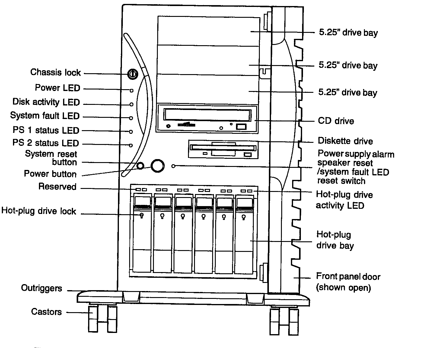
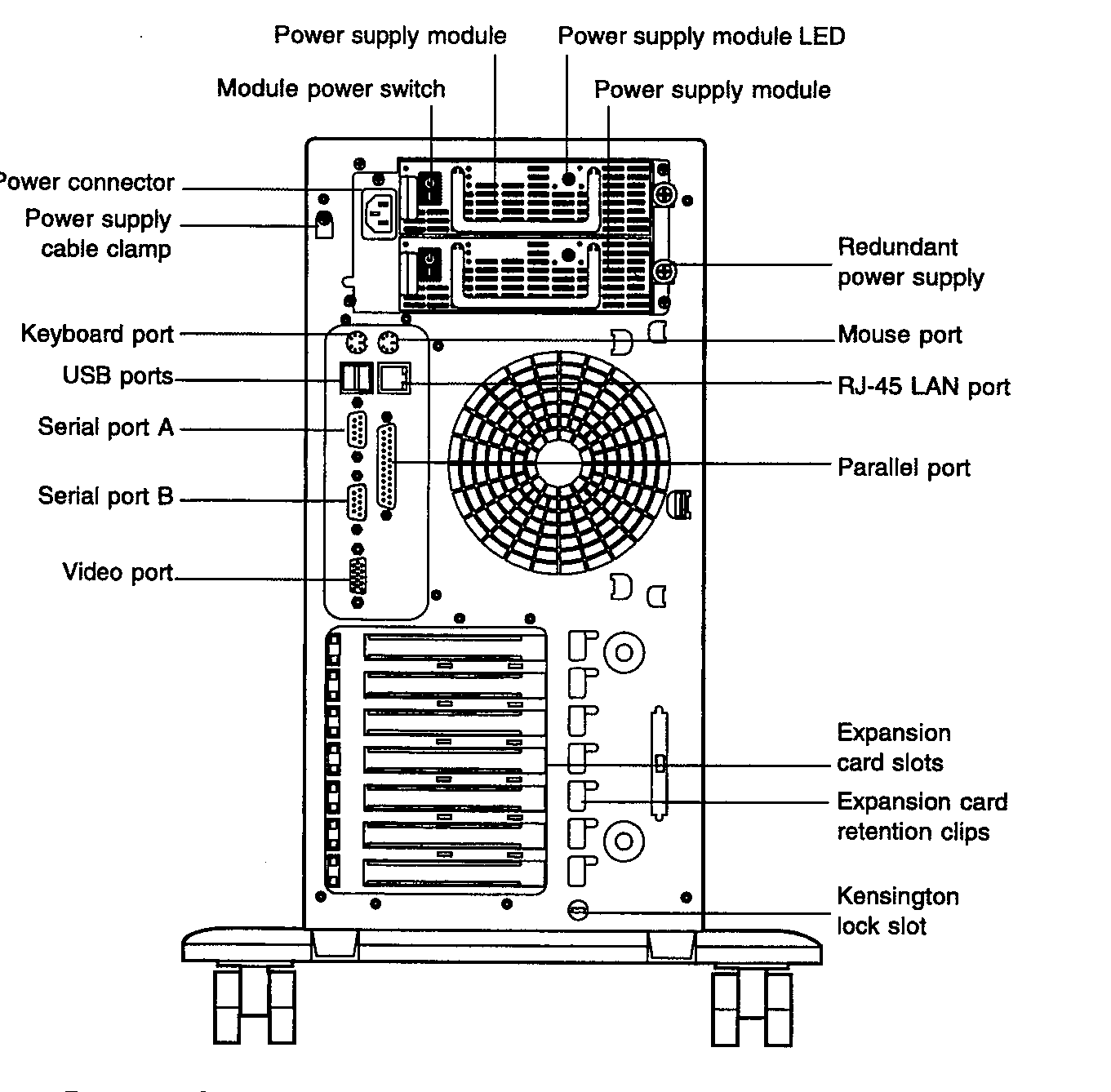
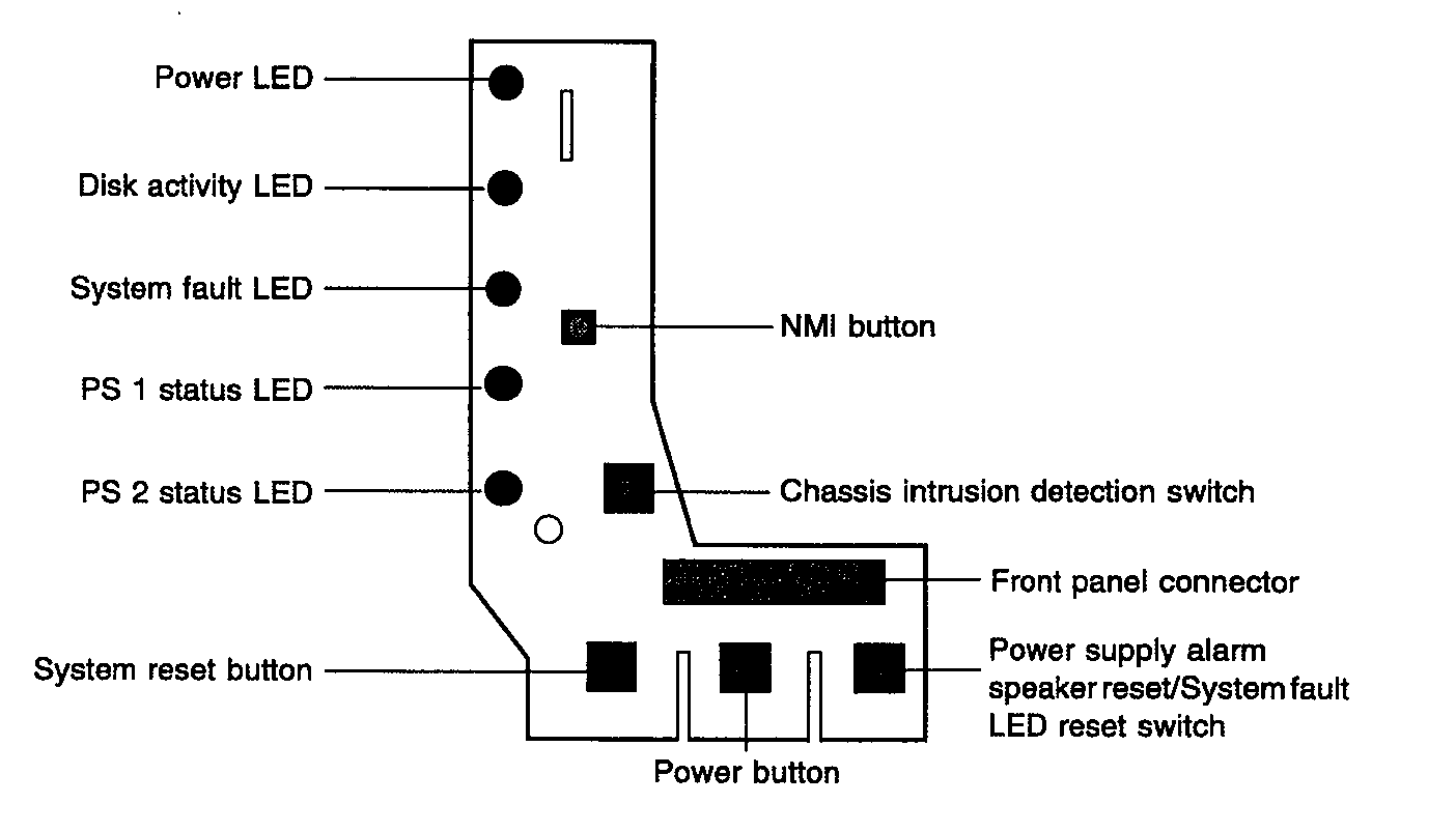
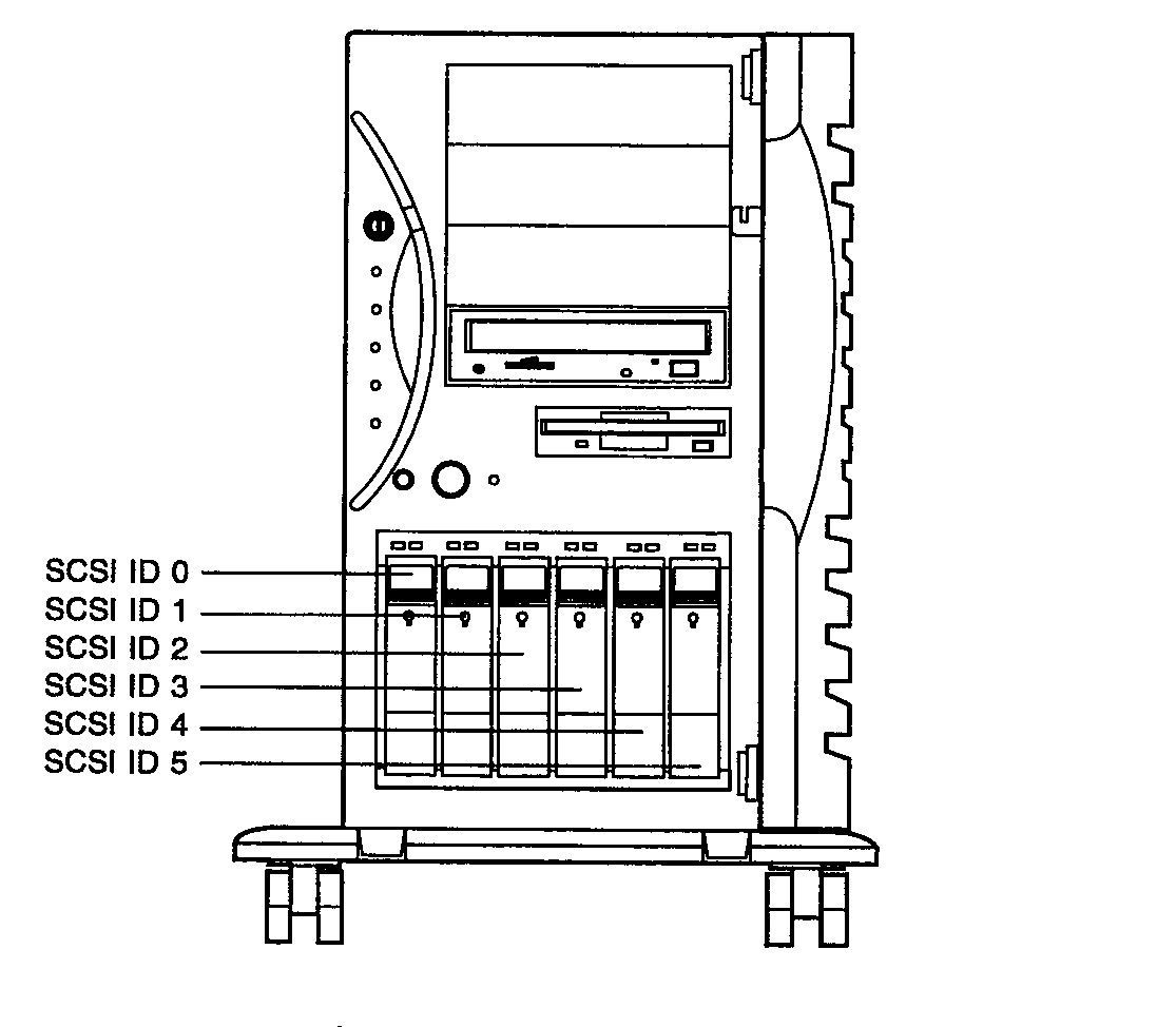
Front
|
| 4.6 |
 |
| 4.7 |
 |
| 4.8 |
DR300 |
|
 |
| 5 |
SUB ASSEMBLIES |
| 5.1 |
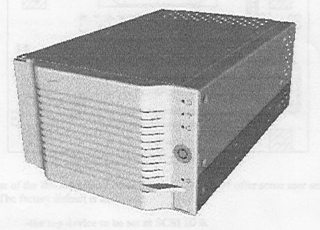
DR300
Cabling to the DR300, the top is Channel One, and if the actual cable has no terminator
then a terminator must be fitted to the SCSI OUT on DR300. |
| 5.1.1 |
The DR300 can house up to three
hard drives. |
| 5.1.2 |
 |
| 5.1.3 |
 |
| 5.1.4 |
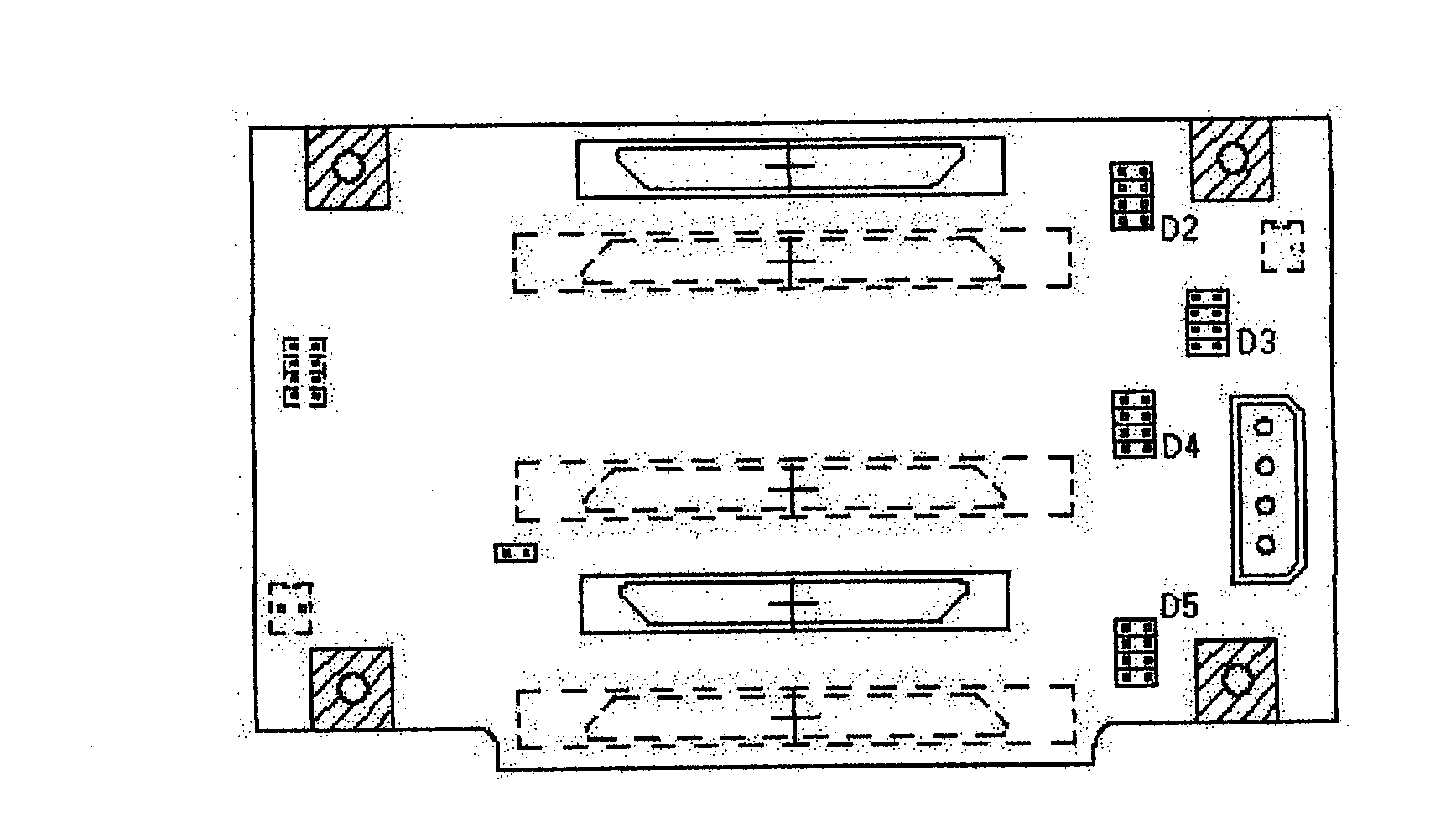
On the rear of the DR300 shown
above are the jumper blocks. Leave the SCSI ID's to the factory default
Top device SCSI ID 0
Middle device SCSI ID 1
Bottom device SCSI ID 2
Immediate & local spin up
Fan fail set to visual & audible alarms
CHECK JUMPER SETTING |
| 5.1.5 |
Jumper Block D3 AUD
adding this jumper will silence the audible fan fail alarm but leave the visual fan fail
alarm functioning
RMT* adding this jumper prevents the device from spinning up until it
is signaled by the host controller. On boot up as the host scans the SCSI bus each device
is brought on line in turn.
DLY* adding this jumper activates the delayed spin up mode of the
installed device.
This generally delays the initial spin up of the device for a given time period to
allow a number of devices to spin up sequentially, thus spreading the peak power demand on
the power supply. The time delay is based on a multiple of the SCSI ID number and may vary
from one manufacturer to another.
*These features are selected for all 3 devices, different devices within a DR300 cannot
have different start up selections. |
| 5.1.6 |
Remove all ID jumpers from the
actual device and use only the jumpers on the DR300 |
| 5.1.7 |
The DR300 will house any industry
standard 3.5" x 1" high single connector device. Device must be mounted on a
Lapis Solutions device carrier, and locked into position using the camming lever. |
| 5.1.8 |
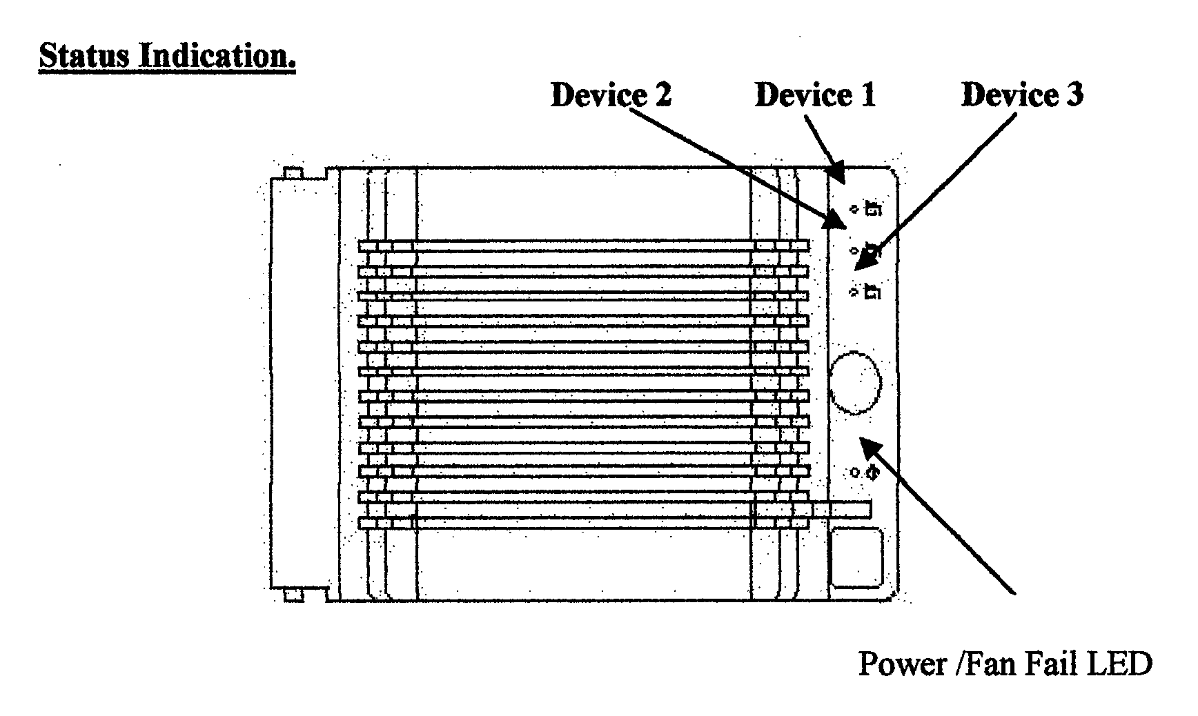
The DR300 offers both visible and
audible information concerning the status of the unit. Power/ Fan Fail
The Fan Fail LED indicates either a 'normal' or a 'filed' condition, Green being normal
and red being a fail condition.
There is, in addition, an audible warning of a fail condition which can be silenced if
required by the removal of jumper J2 on the door mounted pcb.
Device Presence Each device position has a dedicated LED to show the
presence of the device. With a device installed the LED is on, with no device the LED will
be off.
Device Activity The above LED will flash when the device is active. |
| 5.2 |
4mm DAT Tape Deck Seagate
STD 2401LW
DDS4 Technology
Backwards compatible to read tapes from 3400 & 3800.
Not backwards compatible for DDS4 tapes created on it to be read by 3400 (DDS-1)or 3800
(DDS-2)
DIP switch settings 1 = OFF 2 onwards ON
Connection for SCSI ID = 4
NOTE: Wrong DIP switch settings will give the wrong identity of the manufacturer. |
| 5.3 |
CD ROM Hitachi CR 594
– C IDE must be set for Master |
| 5.4 |
FLOPPY Panasonic JU
256A216P |
| 5.5 |
Hard Disks IBM Ultrastar
DDYS – to 9/70 9.1GB
Seagate Cheetah ST 318404LC 18GB |
| 5.6 |
I/O pcb & pod
Digiboard Digi-Acceleport-920-PCI-8P internal pcb
Digiboard Digi-D25M-DTE-BOX-8P 8 port pod. |
| 6 6.1
6.1.1
6.1.2
6.1.3
6.1.4
6.1.5 |
DISASSEMBLY
To access the interiorRemove front panel by depressing the release pads either
side.
To remove the left hand side, undo the 3 bright green knobs on the left front.
Use the handle on the left panel front to pull the panel forwards, and remove.
The interior is now accessible.
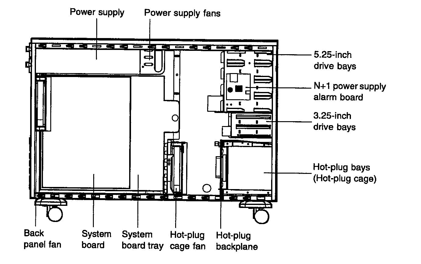
The diagram below shows the lay out |
|
 |
| 6.2 |
To Remove a PSU At the
rear, undo the screws and remove the PSU.
Note. Both PSU fans run - even when 1 PSU is removed. |
| 6.3 |
To remove Fans. NOTE:
All fans are monitored, so that is why they have 3 wires going to them.
Access the interior.
To remove a fan, squeeze the coloured parts, and they can be removed. Disconnect the power
lead.
There are 2 x 120mm, and 1 x 60mm fan. The DR300 also has a fan.
NOTE: The PSU fans will both operate even with one PSU removed. |
| 6.4 |
To Remove Disc from Hot-Plug
Drive Bay
Open the front door.
If the rive carrier is locked, use a hex key to unlock it. A red flag indicates locked.
Press down on the carrier handle and rotate it downwards; and when it releases, pull the
carrier and drive out. |
| 6.5 |
To Remove the DR300
Access the interior.
Disconnect all cabling
Release the two tabs at either side and withdraw it completely |
| 6.6 |
To Remove a Media Drive from
the DR300
Remove the front panel.
Unlock the DR300 front door and open it to access the inside.
On the Media drive carrier, Press the vertical coloured locking tab to the right to
release the metal camming lever, which is pivoted on the left.
Pull the right hand side of the camming lever until the carrier is released
and withdraw the media drive. |
| 7 |
SCSI CONTROLLER
Ensure the BBU is disconnected before insertion or removal of DIMM's. |
| 8 |
MOTHERBOARD
With only one CPU installed then a terminator must be fitted to CP2 No2.
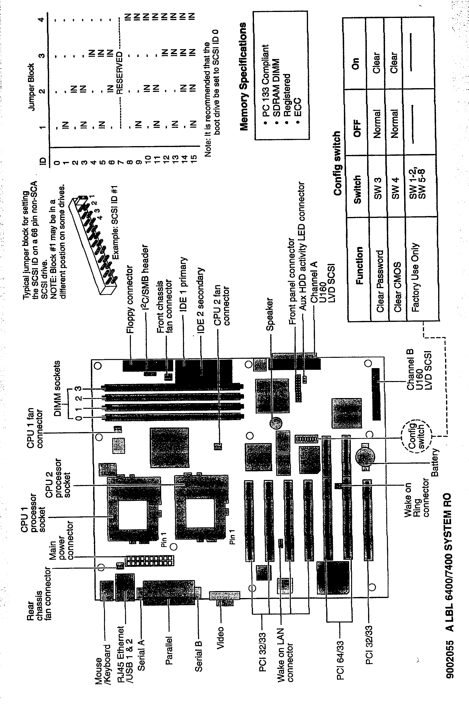
Jumpers & config SW motherboard – standard setting |
|
Motherboard Layout below |
|
 |
| 9 |
CABLE SPECS Existing
Standard EDP Cables are used on the Comm Ports and Digi Connectors, as well as Standard
CAT5 Network Connection. |
|
FA DIGIBOARD to VDU /
SERIAL PRINTER
FB1 DIGIBOARD to NDR SERIAL PRINTER
FC DIGIBOARD to PARALLEL PRINTER
FD DIGIBOARD to PC (9 pin) VIADUCT
FE DIGIBOARD to PC (25 pin) VIADUCT
FF DIGIBOARD to MODEM (UniCom, UniFax, Diagnostic Modem)
FG DIGIBOARD to VDU / SERIAL PRINTER (3 wire)
FH DIGIBOARD to MODEM
FJ DIGIBOARD to RTC CABLEHE1
DIGIBOARD -- WALLSOCKET
HA
WALL SOCKET -- VDU / PTR
HE1 DIGIBOARD -- WALLSOCKET
HC
WALLSOCKET -- PC (25pin)
HD
WALLSOCKET -- PC (9pin)
HF DIGIBOARD -- WALLSOCKET
HG DIGIBOARD -- WALLSOCKET
HH
WALLSOCKET -- VDU / PTR
HW1 TALLY 6045 Digiboard - PTR Converted FG 3 wire
HY TALLY 6045 Digiboard - PTR Converted FA 7 wire)
HE1 DIGIBOARD -- WALLSOCKET
HZ
WALLSOCKET -- TALLY 6045
JF STANDRD CAT5 CABLE
JP STANDARD CAT5 CROSSOVER MIDI X
CABLE |
| 10 |
SCSI controller – ensure BBU
is disconnected before insertion or removal of DIMM's.
With only one CPU installed then a terminator must be filled to CP2 No2.
Jumpers & config SW motherboard – standard setting |
| 11 |
INITITAL CONFIGURATION check
and set the following |
| 11.1 |
Switch System on
When running up you have to be quick to pressF1 – setup
Tab
Ctrl C setup
Displays on board SCSI
Adapter properties
53C1010 - 33 PCI bus 1 dev/Fma29
Properties
SCSI Parity
Yes
Host SCSI ID
7
SCSI Bus Scan Order Low to high 0..Max
Removable Media Support None
CHS Mapping
SCSI Plug & Play Mapping
Spin up delay secs
0
2ndary cluster server No
terminator control
Auto
displays SCSI numbers 0
¯
15
SEAGATE DAT 0624- XXX 8040
Note all SCSI ID must be below 7 |
| 12 |
BIOS SETUP UTILITY Set time
& date in the Main Menu.
Advanced set-up, look but don't touch |
| 12.1 |
Super IO configuration
On board controller
Enable
Serial Port 1 Address 3F8
Serial Port 1 IRQ
4
Serial Port 2 Address 2F8
Serial Port 2 IRQ
3
Parallel Port Address 378
IRQ 7
Mode ECP
ECO MODE DMA Channel 3 |
| 12.2 |
IDE Configuration Onboard
IDE Controller Both
Primary IDE Master
ATAPI CDROM
Primary IDE Slave
Not detected
Secondary IDE Slave
Not detected
Secondary IDE Slave
Not detected
ATPI Detect Time Out 0
|
| 12.3 |
Floppy Controller Floppy
A 1.44 |
| 12.4 |
PCIPnP Configuation Reset
Configuration Data No
PCI Latency Timer
64
Allocate IRQ to PCI VGAYes
PCI IDE BusMaster
Disabled
USB Function
Enabled
Legacy USB Function Disabled
|
| 12.5 |
Boot Setting Configuration Quick
Boot
Enabled
Quiet Boot
Enabled
Boot Num Lock On
Bootup CPU Speed High
PS/2 Mouse Support Enabled
Typematic Rate Fast
System KB
Present
Parity Check
Disabled
Wait for F1 if error Enabled
Internal Cache
Writeback
MPS 1.4 Support Enabled
Power Failure ControlPrevious State
|
| 12.6 |
Onboard Device Configuration Onboard
SCSI
Enabled
Onboard SCSI Option ROM Enabled
Onboard Intel NIC82559 Enabled
|
| 12.7 |
System health monitor
Review |
| 13 |
Power |
| 13.1 |
Power Management
Enabled
Green PC Monitor Power State Standby
Video Power Down
Standby
IDE Drive Power Down Mode Disabled
Inactivity Timer
Off
Suspend Time Out Minutes Off
IRQ1
Monitor
IRQ12
Monitor
IRQ14
Monitor
USB Controller Resume
Disable
PME Resume
Enabled
RI Resume
Disabled |
| 14 |
Boot |
| 14.1 |
Boot Device Priority 1st
Boot Device Removable Device
(floppy)
2nd Boot Device ATAP CDROM
3rd Boot Device Hard Drive |
| 14.2 |
Hard Disk Drives 1st
Hard Disk Drive [ ]
2nd Hard Disk Drive [ ]
3rd Hard Disk Drive [ ]
4th Hard Disk Drive [ ] |
| 14.3 |
Removable Devices 1st
Removable Device 1st Floppy |
| 14.4 |
ATAPI CDROM Drives 1st
ATAP CDROM MATSHITA CR594 |
| 15 |
Security DON’T TOUCH
THIS |
| 15.1 |
Change Supervisors Password
Change User Password
Clear User Password |
| 15.2 |
Exit |
| 16 |
SCSI setup CTRL – M
Mega RAID BIOS configuration |
| 16.1 |
Don't use Easy Configuration |
| 16.2 |
Select New configuration |
| 16.3 |
View Add Configuration |
| 16.4 |
Clear Configuration |
| 16.5 |
Note if upgrading data drives
only do this.
-
Clear configuration - gets rid of root & data
-
Create both packs root & data
-
Initialise only data pack logical drive 2
|
| 16.6 |
Management menu and explanation Config
Init
Objects
Format
Rebuild
Check consistency |
| 16.7 |
Configuration
Easy don’t use this
View Add Configuration
Clear Configuration |
| 16.8 |
Initialise
Initialise packs
use spacebar
Quick format |
| 16.9 |
Objects
Adapter - gives info take default
Logical drives 1/2 Initialise Clear Update
Check Consistency
Physical shows drives
Rebuild Format Online Fail Hotspare etc
Model etc |
| 16.10 |
Format Formats drive Take
Off Line first |
| 16.11 |
Rebuild Only if drive
has failed or you are replacing the drive |
| 16.12 |
Check consistency Bad
track check |
| 17 |
For a New Configuration - typical
example 
A is the root
B1 & B2 ¯ stripe down
¯
® ® and mirror across to
B3 & B4
Use the highlight & spacebar (<SP>) to select A then <CR>
and the pack is made
then F10
Advanced write to WRTBACK
Accept
Raid10 B1 <SP> B2 <SP> <CR> B3 <SP> B4 <SP> <CR>
F10
RAID 1 + YES span = Raid 10 stripe ¯ down B1/B2 same
channel
¯
Mirror across ® ®
B3/B4 different channel
For a non new system, don’t initialise just reboot ie with data on root |
|
For a brand new system |
| 18 |
Initialise both logical drives Select
F10 to initialise then Y |
| 19 |
Exit Mega Raid BIOS |
| 20 |
CTRL - ALT – DEL |
| 21 |
LOAD OF UNIX SVR4 |
| 21.1 |
There are No diagnostic Media and
No SSU Media |
| 21.2 |
Insert the Maintenance CD
& let it run accept all defaults.
Accept CDROM this should take less than 5 minutes. |
| 21.3 |
Follow prompt & Insert
Core CD Delete & create new partition |
| 21.4 |
Insert Licence flex Add
packages extras
Cacheopt
Mpi
Unlimusr
Mouse type
Rebuild – no
2 R5 VGA 800 x 600 x 8 256 colours
default
slicing swap = 2 x memory
stand = 50
root = 250
dump = 512
var =
250
new = 1000
|
| 21.5 |
Insert Maintenance Media |
| 21.6 |
Pkgplus selection patches Amirdman |
| 21.7 |
Is pkgplus being run to create
configuration files for machine other than the current machine Y/N N |
| 21.8 |
Load to this point is approx 35
minutes. |
| 21.9 |
Reboot |
| 22 |
Network configuration (example
only)
Set the IP address
i.e. Brian 128.2.60.5
255.255.0.0
standard setting |
| 23 |
rollback
Y
Load pts
Insert floppy
Enter tar Ñ xv <CR>
pts.menu <CR> |
| 24 |
Keyboard
Insert floppy.
Enter pkgadd Ñ -d Ñ diskette 1 |
| 25 |
AMI patch 03.02.00.5 Amirdman
patch |
| 26 |
Use pts.menu to add an
extra com port as the system comes with only one configured. |
| 27 |
Use pts to tune
Memsize
Set STRTHRESH to 2x8000000
UFSNINODE 4500
VXF_NINODE 500
r to rebuild
|
| 28 |
Alt-PrintScreen H |
| 29 |
Login to root |
| 30 |
Root |
| 31 |
To Create ports use
sysadm
Port 00 is there already present but modify it to 19200
exit
|
| 32 |
LOAD OF APC POWERCHUTE UPS
SOFTWARE |
| 32.1 |
Enter listdrives to show
the drives then mount the CD
mount Ñ -F
Ñ cdfs Ñ -o Ñ
ro Ñ / dev / cdrom / cdrom1 Ñ /
mnt
cd Ñ / mnt /
NCR
sh Ñ . /
INSTALL |
| 32.2 |
prompt for media 1
for CD |
| 32.3 |
Prompt for path <CR
> if correct See overview Y |
| 32.4 |
Which parts of power chute
plus for Unix do you wish to install? 3 both the user I/F & Daemon
Modules |
| 32.5 |
Which APC hardware will PCT
for U be running with 2 Smart UPS 2 Do you have measure ups attached
NO
7 NCR (AT & T UNIX) |
| 32.6 |
On which Operating System
Do you wish to provide power protection for run-level 1 N
Do you currently have TCP/IP installed
N
Which serial device will be dedicated to PC + 4U
2 /dev/term/01
Where do you wish to install PC+4U /ect/powerchute Y
Displays parameters
Are the above selection current
Y
Installs PCT4U |
| 32.7 |
Rename In root superuser
Enter / ect / re2.d /S98upsd Ñ rename
s96upsd |
| 32.8 |
Reboot |
| 32.9 |
umount Ñ
/ mnt Remove the CD |
| 32.10 |
UPS
cd Ñ / etc / powerchute
Enter . / powerchute
CNTL-G Þ Config ß Event Actions
<CR>
Tab to "power chute started " top left hand column,
arrow down ß to "ups on battery" press space
bar ( <SB> )to high light it.
Tab across, press tab till "shut down server" is high lighted.
tab again to get to options press <CR>
tab to Begin shutdown sequence in [300] & change figure to 900
tab to ok & <CR>;
Tab till you get to ok press <CR>
CNTRL-G arrow ß down highlight exit & <CR>
|
| 33 |
DIGIBOARD CONFIGURATION Mpi
Menu Port Interface for Digiboard Configuration |
| 33.1 |
Main menu
Config
Install
Digi accelport Xr family
Boards
1
board type
Digi _ Accelport_8r_PCI(EIA-232/RS-422)
F5
Digiscreen install N
Altpin setting OFF
Follow prompts
|
| 33.2 |
Rebuild kernel |
| 33.3 |
Configure a port Enter sacadm
–1
We use r Ñ la à
r/h
Sysadm
port
port mon
Add digimon
ttymon
/ usr / lib / saf / ttymon
r Ñ la - 19200 r/b
in example ports 1 & 2 set to 19200
ports 3 to7 set to 9600
port 8 set to autoNP
|
| 33.4 |
To create filing system
sysadm
Storage
Device Configuration & Maintenance
Partition
Device name F2 for choices
c120 t0 d1 s0
save
root
c120 t0 d0 s0
Full Unix partition
Y
Slice
|
| 33.5 |
Slice 1 charisma 1
Slice 2chartest
Slice 3UniVision
|
| 33.6 |
Create filing system |
| 34 34.1 |
LOAD UNIVISION mount
Ñ 1F Ñ cdfs Ñ
-o Ñ ro /dev/cdr………..etc
pkgadd Ñ -d Ñ / mnt / ncr
Y |
| 35 |
Enter mivi login
Enter UnLockCode
Configure Registry Y
Flavour
A
|
| 36 |
Base Configuration Complete |
|
Return to Index
|
