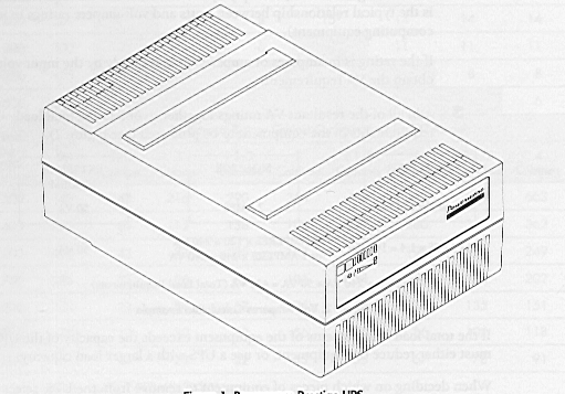
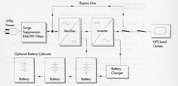
4. SAFETY CAUTIONS -
NOTE WELL!
4.1 Batteries can present a risk of
electric shock or burn from high short circuit currents. Always
observe the
proper safety precautions.
4.2 The UPS contains its own energy
source so the output receptacles may carry live voltage even
when the
UPS is not connected to an AC supply.
4.3 Do not remove or unplug the input cord
when the UPS is turned on as this removes the safety
ground from the
UPS and the equipment connected to the UPS.
5. STACKING
5.1 The cabinets may be stacked vertically or
horizontally. Do not stack more than three battery
cabinets in one
stack. In vertical stacks the UPS cabinet MUST be placed on the top of the stack.
5.2 Make sure the circuit breaker on all battery
cabinets is OFF.
5.3 Connect the battery cable from the first
Battery Cabinet into the UPS Cabinet.
Then connect the
battery cable from the second Battery Cabinet into the first, then the third into
the second, etc.
5.4 Turn the circuit breaker on all the
Battery Cabinets to the ON position.
6. START UP VOLTAGE CHECK
6.1 Plug the UPS power supply cord into the
input connector on the UPS rear panel.
6.2 Plug the other end of the UPS
power supply into a grounded, three-wire, AC receptacle that has
been wired in
accordance with IEC specifications.
NOTE :
Steps 6.3 through 6.6 are for changing the
output voltage. The output voltage is
factory-configured for 230V. check it is correct. If you do not need to change the
output voltage, skip to step 6.7.
6.3 Press the Output OFF button until the
alarm beeps.
All
indicators flash simultaneously.
6.4 Press and hold the Output | On button
until the alarm beeps again.
Two
indicators, corresponding with the current setting, remain flashing. The output voltage is
factory-configured for 230V.

6.5 Press the Output OFF button to
scroll through the output voltage options, top to bottom. Each time
you
press the button, the UPS beeps and the next two indicators flash.
NOTE : If you do not
save a selection within two minutes, the setup automatically aborts
and switches back to the original configuration.
6.6 Press and hold the Output
| On button until the alarm beeps to select and save the output
voltage. Failure to release the button immediately after beep will cause the UPS to abort
the
setup.
7. INITIAL COMMUNICATIONS
SETTING
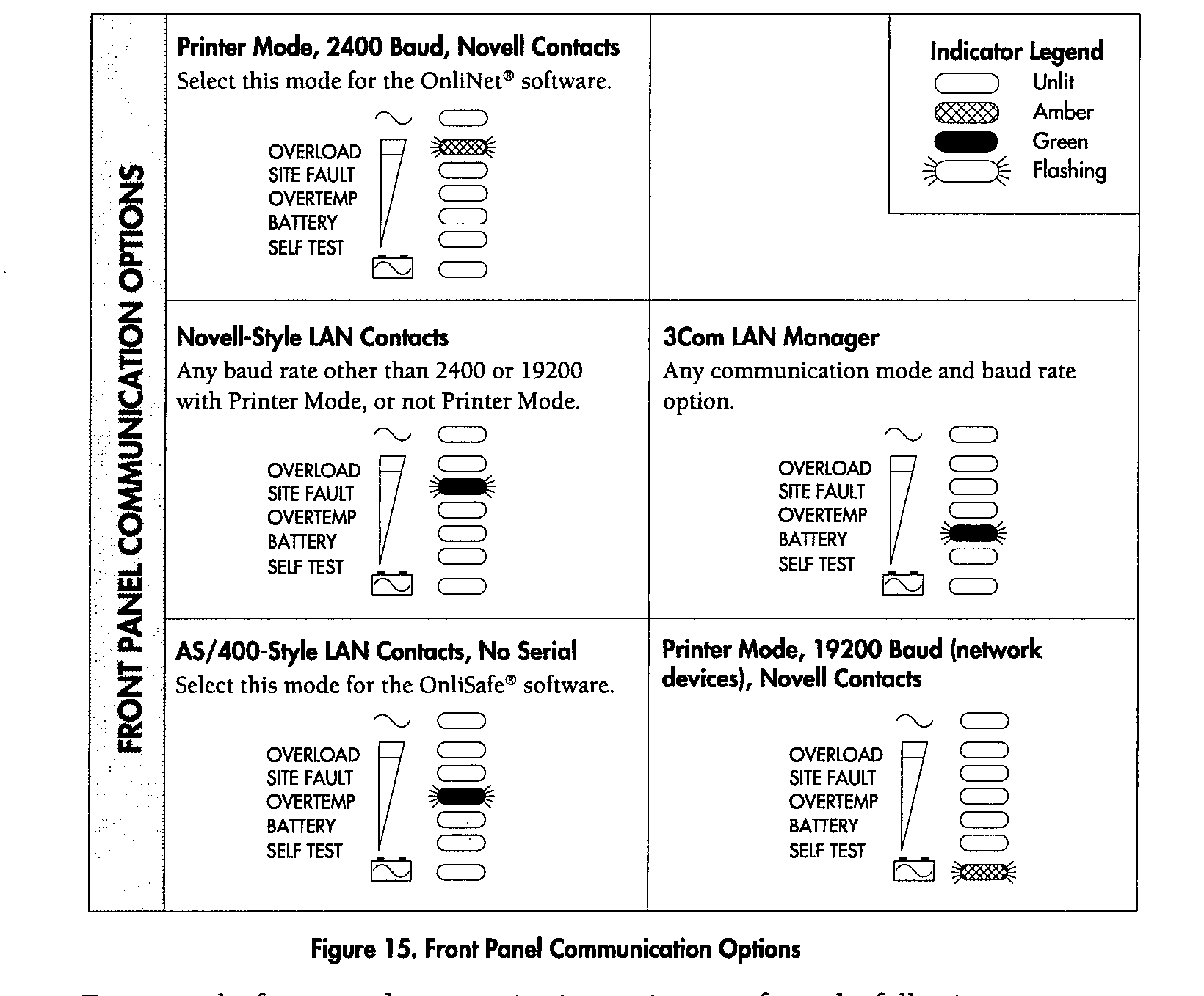
7.1 Before you access the
front panel, review the following configurations in Figure 15, and note
the
indicator that corresponds with the communications mode required.
For Orderly
Shutdown:- Printer Mode
For Power
Fail Recovery:- AS/400-Style LAN Contacts, No Serial
7.2 Press and hold the Output
Off button until the long bleep ceases (approx three seconds)
7.3 Disconnect the mains input power,
and wait until all indicators extinguish.
7.4 Reconnect the mains input power whilst
holding the Output Off button, until the alarm beeps.
All
indicators will begin to flash.
7.5 Press and hold the Output Off button a
second time until the alarm beeps again.
7.6 A single indicator, corresponding
to the current setting will remain flashing.
7.7 Press the Output Off button to scroll
through the communications options, top to bottom. Each
time you press
the button, the UPS will bleep and the next indicator will flash.
NOTE :
If you do not save a selection within two minutes, the setup
automatically aborts
and switches back to the original configuration.
7.8 Press and hold the Output |
On button until the alarm beeps to select and save a
communications
option. Failure to release the button immediately after beep will cause the
UPS to abort the
setup.
Press the
Output | On button again to return the UPS to Normal Mode.
8. EQUIPMENT CONNECTION
8.1 On the UPS press and
hold the Output Off button until the UPS switches off its output and the
lamps are
extinguished. The equipment to be protected by the UPS should also be powered off.
Plug the
equipment into the power outlet receptacles on the UPS rear panel. Connect the
appropriate UPS
communications cable from the UPS to the system comms port
Cable Type JM for
Orderly Shutdown using Lansafe III See FECO LVC # 9
Cable to be
advised for Power Fail Recovery using PowerMon II Ver 3.3 See FECO LVC # 10.
8.2 DO NOT protect laser printers with the
UPS because of the exceptionally high power requirements
of the heating
elements. The optional PowerPass has a surge-protected receptacle for laser printers.
8.3 Turn on the equipment that is connected
to the UPS.
8.4 Press and hold the Output | On button
until you hear the UPS beep (approximately one second).

8.5 The ~ Indicator remains lit and
the Self Test Indicator turns on. The front panel displays the
percentage of
full load being applied to the UPS. The UPS is now in Normal Mode with the load
online.
8.6 The UPS is initially shipped with the
battery charged, however it may lose some of its charge
during shipping
and storing. Upon initial start up the UPS may need to operate for approximately
8 hours before
the battery is fully charged and full back up time is available. If the Battery Fault
Indicator
flashes, operate the UPS for 24 hours to fully charge the battery.
9. UPS FRONT PANEL INDICATIONS
9.1 Front Panel Description
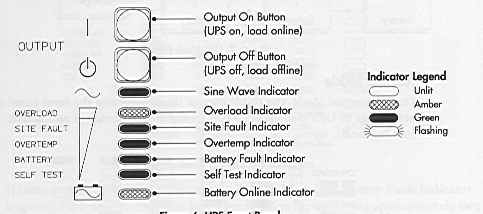
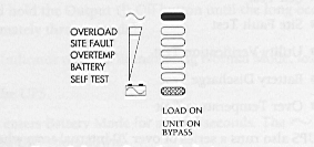
9.2 Normal Mode

9.3 Bypass Mode
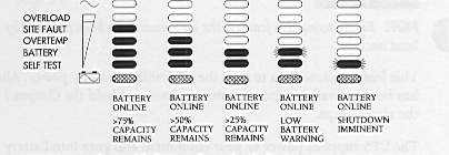
9.4 Battery Mode
10 DIAGNOSTIC
10.1 The UPS periodically performs diagnostic
tests while the unit is operating in the Normal Mode,
ensuring proper
operation.
These tests
include :-
Self Test
Site Fault Test
Utility Verification Test
Battery Discharge Test
Over Temperature Test
The UPS also runs over 20 tests when power is first applied.
11. UPS SHUTDOWN
11.1 This removes the output power. Ensure attached
equipment is prepared for power-off before
shutting
down the UPS.
11.2 Press and hold the Output Off button until the long bleep
ceases (approx. 3 seconds).
The Sine Wave
Indicator remains lit indicating Normal Mode Load Offline.
11.3 Unplug the UPS.
The UPS enters
Battery Mode for several seconds.
The Sine Wave
Indicator turns off and the UPS shuts down.
12. For other Functions and Features refer to
the Operators Manual.
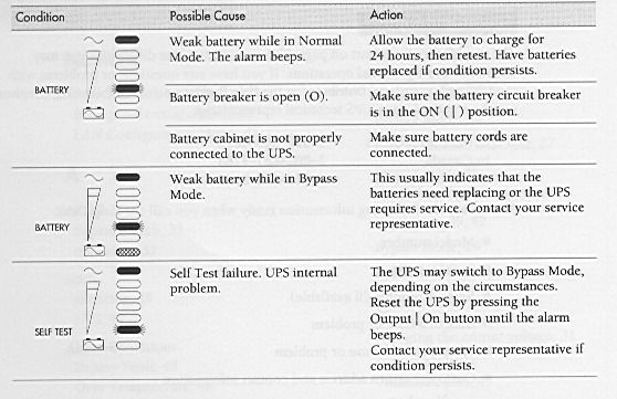
13. TROUBLESHOOTIING
The Prestige
UPS is designed for durable, automatic operation and also alerts you whenever
potential
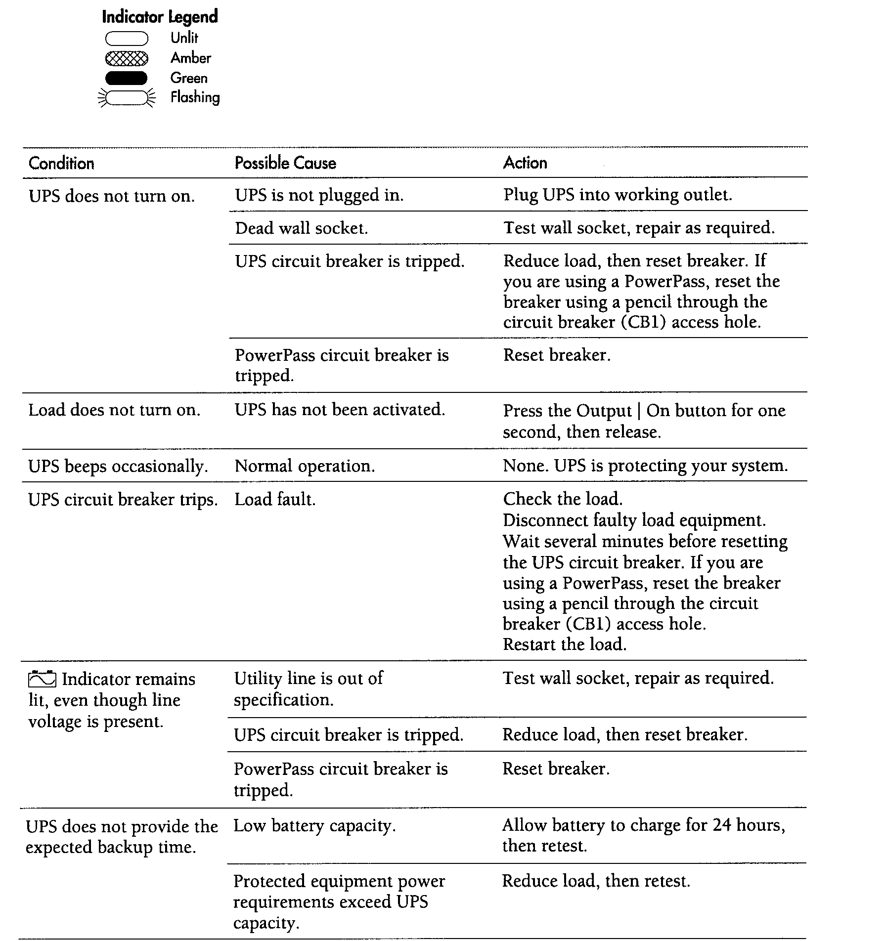
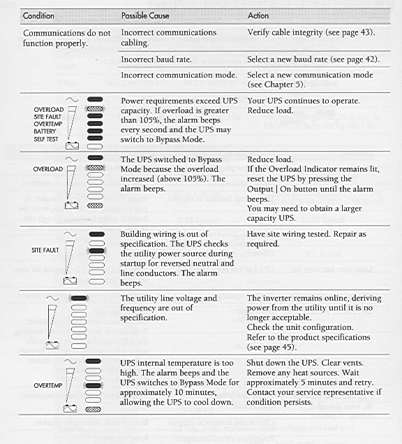
operating problems may occur. Use the following troubleshooting chart to determine
the UPS alarm
condition.
Resetting the UPS
To reset the UPS while an alarm condition is present, press the Output | On button
until the UPS alarm beeps.
Silencing the Alarm
To silence the alarm for an existing fault, press and hold the Output | On button for
one second. The alarm becomes quiet. If UPS status changes, the alarm beeps, overriding
previous alarm silencing. Press the Output | On button again to silence the alarm.
13. MEC IDENTITY
PW - PRESTIGE - 1000VA (UPS)

