TALLY # 94
 |
FECO:
|
TALLY
# 94 |
|
MODIFICATION
NO:
|
N/A |
|
PRODUCT:
|
T6045 |
|
SUB-ASSEMBLY:
|
N/A |
|
ESTIMATED
MAN HOURS:
|
N/A |
|
CLASS
OF CHANGE:
|
INFORMATIONAL |
|
REASON
FOR CHANGE:
|
INTRODUCTION
OF A NEW PRINTER |
|
RELATED
FECO/AB
|
NONE |
TALLY T6045 PRINTER.
1. INTRODUCTION
EDP introduces the Tally T6045 heavy duty printer. This is the smallest of the heavy
range, which also consists of the T6090, T6091, T6140 and T6180.
- SPECIFICATION
Speed up to 450 lpm
Workload 80,000 ppm
Up to 6 port paper
Noise 55dba
Weight - tabletop 79lbs, packaging extra.
pedestal 44lbs
Power peak current 1.8A average 0.7A idle 0.2A.
Heat output maximum 615 BTU/h. Average 280 BTU/h.
Serial and parallel interface the serial I/F DOES NOT have standard pinout.
Printer by hammer mechanism and variable speed shuttle.
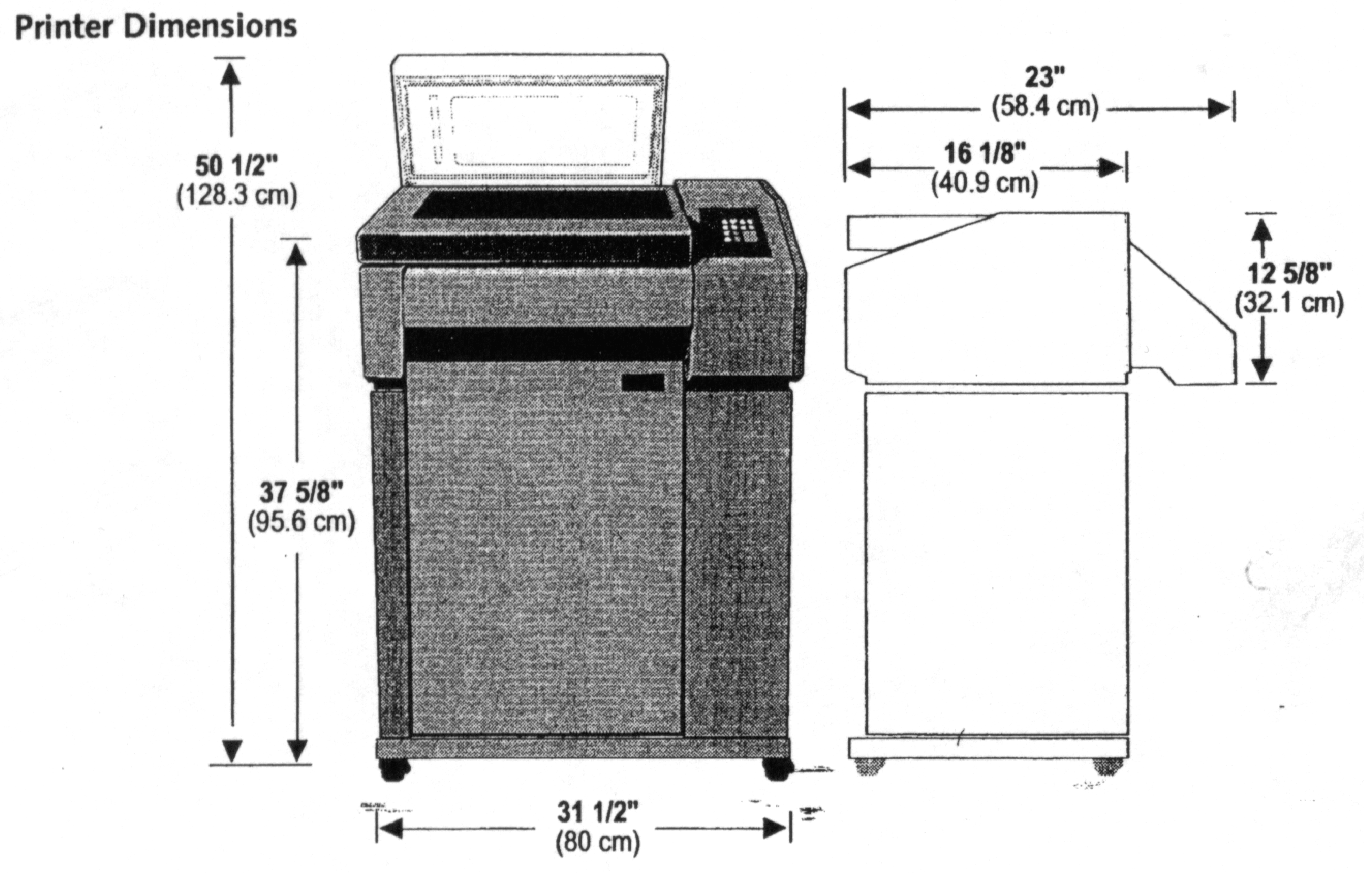 Dimensions shown below.
3. MEC IDENTITY
TALLY – T6045
4. INSTALLATION
4.1 For details refer to the manual supplied with the printer.
4.2 Remove all packaging and shipping bolts/restraints.
- Install on stand/pedestal/table top and then install any other optional features.
Position in designated location. Connect data cable(s).
- Installing Ribbon Cartridge.
- Ensure printer is Off line and powered OFF.
- Open printer lid and raise Form Thickness Lever to the fully open position (up).
- Remove new ribbon from its packaging.
- Remove the slack in the ribbon by turning the knob on the ribbon cartridge clockwise,
then slip the ribbon over the two ribbon guides and between the front and rear panels of
the ribbon shield on the printer.
- Press down lightly on the cartridge whilst turning the knob clockwise, until it seats
correctly on the cartridge post.
- Ensure that the ribbon does not twist or fold over.
- Lower the Form Thickness Lever.
- Loading Paper.
- Ensure that the printer is Off line and powered OFF.
- Position the paper supply underneath the printer.
- Raise the printer lid and the Form Thickness Lever, open both tractor doors. (For
tabletop and stand configurations, make sure that the silencer is open).
- Feed the paper up and through the printer, passing the paper between the front panel of
the ribbon shield and the platen, up past the tractors through the upper paper guide and
out of the rear paper slot.
- Place the left side paper hole onto the left side tractor pins and close the tractor
door.
- The left end of the scale on the ribbon platform marks the position of Column 1. Before
printing make sue that this marker is aligned with the desired position on the form. If
not, unlock the tractor and slide to the desired position before relocking it.
- Unlock the tractor, position it to accept the holes onto the tractor pins, then close
the tractor door. Gently push the tractor to the right until the paper is smooth and
reasonably taut, then lock the tractor.
- Lower the Form Thickness Lever.
- Power the machine ON.
- Set Top of Form (TOF).
Ensure printer in Offline.
Use the UP key or LINE FEED key to position the perforation at the top edge of the
tractors, then press the TOF key. The paper will then move to the correct position.
You may made to raise the wire cover on the Upper paper Guide in order to see the area
at the top of the tractors clearly.
- MENUS
- In general, set-up configurations are found in the NORMAL, OPERATOR, CONFIGURATION and
TEST menus.
- Access usually is by having the printer Offline, then pressing the MODE button and then
the Up Arrow button to display the required main menu; then pressing the FORMS 1 button
and the Up Arrow to display the required Level 1 category; then pressing CP12 and the Up
Arrow to display the required Level 2 category; then pressing LP13 and the Up Arrow to
display the required Level 3 category, and finally the ENTER button to select.
- SAVING MENU CHANGES.
- Ensure printer is Off line
- Press MODE then press Up Arrow until CONFIG disaplayed
- Press FORMS 1 then press Up Arrow until Printer displayed
- Press CPI 2 then press Up Arrow until Save displayed
- Press LPI 3 then press Up Arrow until Powerup displayed
- Press ENTER and display should show Saved for 2 secs
- Press CLEAR to exit.
- TEST PRINTOUTS
- Put printer Off line
- Press MODE then press Up Arrow until TEST displayed
- Press FORMS 1 then press Up Arrow until Pattern displayed
- Press CPI 2 then press Up Arrow until Print displayed
- Press LPI 3 then press Up Arrow until desired test displayed.
- Press ENTER to print
- Tests available:-
Upper upper case letters only
All Chts all ASC11 characters
63/69 rolling ASC11
ECMA prints to give audible noise
Columns print in columns.
- Press CLEAR to stop test.
- CONFIGURATION REPORT
- Put printer Off line
- Press MODE then press Up Arrow until CONFIG displayed
- Press FORMS 1 then press Up Arrow until Printer displayed
- Press CPI 2 then press Up Arrow until Report displayed
- Press LPI 3 then press Up Arrow until Configs displayed.
- Press ENTER to print
- Press CLEAR when finished
- EDP STANDARD SET-UP on next page
| CONFIGURATION |
CURRENT |
| Emulation |
IBM Pro |
| Shared I/O Hold |
30 Sec |
| Powerup |
Offline |
| Character Styling |
|
| CPI |
10 |
| Font Style |
DP |
| Matrix |
CDF |
| Language GO |
US |
| GI |
N/A |
| Character Set |
CP437-1 |
| Operator Language |
English |
| OCR Standards |
ANS ANS |
| Slashed Zero |
Open |
| Compressed 8 LPI |
OFF |
| Forms Styling |
|
| Form Length |
66 |
| LPI |
6 |
| Bottom Margin |
66 |
| Top Margin |
0 |
| Left Margin |
1 |
| Right Margin |
132 |
| VFU |
Disabled |
| VFU VT Channel |
N/A |
| VFU Skip When |
N/A |
| Control Codes |
|
| Auto LF |
OFF |
| Auto CR |
ON |
| Line Wrap |
ON |
| Wrap LF |
ON |
| FF at TOF |
Enabled |
| ESC |
N/A |
| Alt ESC |
N/A |
| UprOnly |
Disabled |
| Code 7F |
Ignore |
| IgnChar |
OFF |
| SubChrF |
OFF |
| SubChrT |
OFF |
| Graphic |
|
| CVCC |
94 |
| Smooth Size |
3 |
| PY Then |
None |
| PN Then |
None |
| Dark Bar |
Low |
| Modified Plot |
ON |
| Version |
2 |
| Descndr |
Fixed |
| Vscale |
Stylel |
| Slashed Zero |
Slashed |
| SFCC |
126 |
| CV Lang |
US |
| PG Lang |
ASCII |
| FreeFmt |
OFF |
| Automatic Py |
Disabled |
| MTPL Bar |
N/A |
| MTPL Secured |
N/A |
| Parallel Interface |
|
| POPC Enable |
ON |
| 8th Bit |
Data |
| Bi-Directional |
ON |
| Buffer Size |
Dynamic |
| Serial Interface |
|
| Baud Rate |
9600 |
| Data Bits |
8 |
| Stop Bits |
1 Bit |
| Parity |
None |
| 8th Bit |
Data |
| Protocol |
XON/OFF |
| 8ts Eng |
OFF |
| DTR Function |
Busy |
| DTR Polarity |
Actv Lo |
| Busy Polarity |
Actv Lo |
| RTS |
Busy |
| RB Xon |
OFF |
| Buffer Size |
Dynamic |
- ACCESS TO INTERIOR PARTS
- TO ACCESS PSU
At the rear remove the 3 screws holding in the PSU assembly, the panel with the mains
input connector. Gently pull out the PSU assembly, comprising pcb and rear panel; as the
low voltage is hard wired to the rest of the machine.
- TO ACCESS LOGIC PCB.
- There is one main logic pcb, situated inside the RHS panel.
- Remove screw from RH panel at the top rear – approx 6 inches in.
- Remove 2 screws from RHS panel, at the bottom.
- Remove 1 screws from RHS panel at the front bottom left.
- Lift top corner and remove 1 screw from the RHS panel at the front top left.
- Gently lift away the RHS cover. BEWARE!!! There is a cable connecting the control panel
to the logic.
- The logic is mounted vertically front to rear, with details below.
- The rear has the serial and parallel interface.
- The LV connection from the PSU is bottom front.
- Bottom front a connection to the fan mounted in the base of the printer just to the left
of the logic pcb.
- Middle front are the ribbon cable connectors to the shuttle/hammer bank assembly.
- At the top there are 8 connectors to the control panel, sensors and motors.
- The rear interface assembly is held by four screws to the rear panel.
- The logic pcb itself is mounted to the frame on 3 pillars
- TO ACCESS HAMMER ASSY
- Remove ribbon platform assembly by removing the 3 screws, and lifting away the platform
assembly and ribbon motor.
- Access to the hammer assembly is now available.
- CABLE SPECS
- SERIAL
25 pin D Type Male
1 FRAME GROUND
2 TD
3 RD
11&19 RTS
5 CTS
6 DSR
7 SG
20 DTR
Note: RTS is not on pin 4 as in other printers.
11.2 As RTS is not on pin 4, all existing specs must be changed from pin 4 to pin 11.
The following cable specs apply, as at the printer end pin 11 is now wired
in place of pin 4.
Old printer spec New T6045 spec
H GU
EX GV
FG GW
FM GX
FA GY
GA GZ
11.3 PARALLEL
36 pin Centronics Type
- nDATASTROBE
- DATABIT1
- DATABIT2
- DATABIT3
- DATABIT4
- DATABIT5
- DATABIT6
- DATABIT7
- DATABIT8
- nACKNLG
- BUSY
- PAPER END
- SELECT
- nAUTOFEED
- LOGIC GROUND
- CHASSIS GROUND
- + 5 volts
12 SIGNAL GROUND (nSTROBE)
- DATA SIGNAL GROUNDS
14 SIGNAL GROUND (PError, Select nACK)
- nINIT
- nFAULT
- nSELECT-IN
15,33, 34,35 NOT USED
Return
to Index