Back to Contents Page
Installing System Options
Dell™ PowerEdge™ 700 Systems
Installation and Troubleshooting Guide
 Cooling Shroud
System Fans
Memory Modules
Processor
Expansion Cards
System Battery
This section describes how to remove and install the following components:
- Cooling shroud
- System fans
- Memory modules
- Processor
- Expansion cards
- System battery
Cooling Shroud
The cooling shroud provides cooling for the processor and heat sink.
Removing the Cooling Shroud

|
CAUTION: See your System Information Guide for complete information about safety precautions working inside the computer and protecting against electrostatic discharge. |
- Turn off the system, including any attached peripherals, and disconnect the system from the
electrical outlet.
- Remove the bezel. See "Removing the Bezel" in "Troubleshooting Your System."
- Lay the system on its right side.
- Remove the cover. See "Removing the Cover" in "Troubleshooting Your System."
- Disconnect the power cables and hard-drive interface cable connectors from the SCSI
backplane (if applicable) or hard drives.
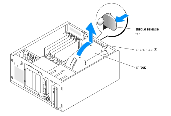
- Press the shroud release tab on the back panel toward the top of the system. See Figure 6-1.
- Gently lift the cooling shroud away from the system board.
Figure 6-1. Removing the Cooling Shroud
Installing the Cooling Shroud
- Ensure that no tools or loose parts are left inside the system.
- Align the anchor tabs on the cooling shroud with the holes in the system chassis.
- Reposition the SCSI and power cables so they do not obstruct the DIMMs and interfere with
installing the cooling shroud.
- Gently lower the cooling shroud until the shroud release tab on the back panel snaps into
place.
- Reconnect the power cable(s) to the SCSI backplane (if applicable) or the hard drive(s).
System Fans
The system includes the following cooling fans:
- Front system fan
- Back system fan
Removing the Front System Fan
|
|
CAUTION: See your System Information Guide for complete information about safety precautions working inside the computer and protecting against electrostatic discharge. |
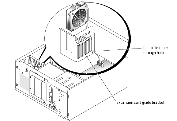
Figure 6-2 illustrates the front system fan inside the system and the fan cable routing hole in the expansion-card guide bracket.
- Turn off the system, including any attached peripherals, and disconnect the system from the
electrical outlet.
- Remove the bezel. See "Removing the Bezel" in "Troubleshooting Your System."
- Lay the system on its right side.
- Remove the cover. See "Removing the Cover" in "Troubleshooting Your System."
- Disconnect the fan cable from the FRONT_FAN connector on the system board.
To identify system board connectors, see Figure A-3.
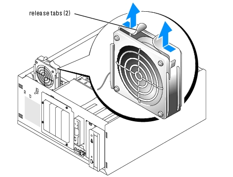
- Press the release tabs on the top of the fan assembly and lift the fan assembly away from the
system until the fan cable and connector are clear of the routing hole in the expansion-card
guide bracket. See Figure 6-2.
Figure 6-2. Removing and Replacing the Front System Fan
Installing the Front System Fan
|
|
CAUTION: See your System Information Guide for complete information about safety precautions working inside the computer and protecting against electrostatic discharge. |
- Insert the fan cable connector into the routing hole in the expansion-card guide bracket. See
Figure 6-2.
- Align the fan assembly with the slots in the chassis and gently lower the assembly into the
chassis. See Figure 6-3.
- Pull the fan cable through the routing hole in the expansion-card guide bracket. See
Figure 6-2.
- Connect the fan cable connector to the FRONT_FAN connector on the system board.
To identify system board connectors, see Figure A-3.
- Install the cover. See "Replacing the Cover" in "Troubleshooting Your System."
- Stand the system upright.
- Install the bezel. See "Installing the Bezel" in "Troubleshooting Your System."
Reconnect the system to its electrical outlet and turn the system on, including any attached peripherals.
Figure 6-3. Removing and Replacing the Front System Fan
Removing the Back System Fan
|
|
CAUTION: See your System Information Guide for complete information about safety precautions working inside the computer and protecting against electrostatic discharge. |
- Turn off the system, including any attached peripherals, and disconnect the system from the
electrical outlet.
- Remove the bezel. See "Removing the Bezel" in "Troubleshooting Your System."
- Lay the system on its right side.
- Remove the cover. See "Removing the Cover" in "Troubleshooting Your System."
- Remove the cooling shroud. See "Removing the Cooling Shroud."
- Disconnect the fan cable from the BACK_FAN connector on the system board. To identify
system board connectors, see Figure A-3.
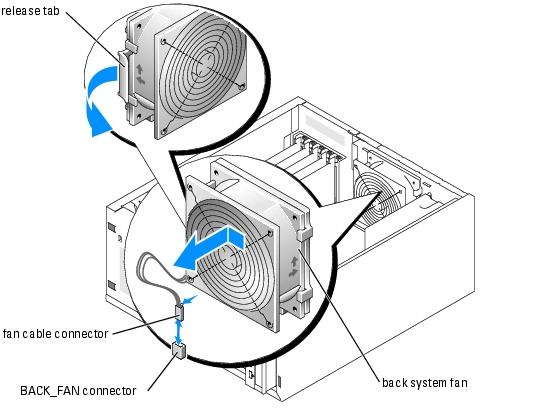
- Pull the release tab on the fan assembly away from the back panel and slide the fan assembly
about 0.63 cm (0.25 inch) toward the expansion-card slots. See Figure 6-4.
- Pull the fan assembly forward and lift the assembly out of the system. See Figure 6-4.
Figure 6-4. Removing the Back System Fan
Installing the Back System Fan
|
|
CAUTION: See your System Information Guide for complete information about safety precautions working inside the computer and protecting against electrostatic discharge. |
- Align the tabs on the fan bracket with the mounting holes in the back panel and slide the fan
assembly toward the power supply about 0.63 cm (0.25 inch) until the fan bracket release tab
snaps into place. See Figure 6-4.
- Connect the fan cable to the BACK_FAN connector on the system board.
To identify system board connectors, see Figure A-3.
- Install the cooling shroud. See "Installing the Cooling Shroud."
- Install the cover. See "Replacing the Cover" in "Troubleshooting Your System."
- Stand the system upright.
- Install the bezel. See "Installing the Bezel" in "Troubleshooting Your System."
- Reconnect the system to its electrical outlet and turn the system on, including any attached
peripherals.
Memory Modules
The four memory module connectors on the system board can accommodate up to 4 GB of memory by installing combinations of 256-MB, 512-MB, and 1-GB unbuffered DDR-400 SDRAM modules. You can purchase memory upgrade kits as needed.
Memory Module Installation Guidelines
The memory module sockets are arranged in banks (1 and 2) on two channels (A and B). Unless only one 256-MB memory module is installed, the modules must be installed in identical pairs. For example, if you are installing 512-MB of total system memory, sockets DIMM1_A and DIMM1_B (bank 1) must contain 256-MB memory modules.
Starting with the connector closest to the processor, the memory module sockets are labeled "DIMM1_A" through "DIMM2_B" (see Figure A-3). When installing the memory modules, use the following guidelines:
- Use only DDR-400 memory modules.
- If you are installing one 256-MB memory module, install the module in the DIMM1_A socket.
- If you are installing 512-MB or more of total memory, install identical memory modules in a bank.
The memory module banks are identified as follows:
- Bank 1: DIMM1_A and DIMM1_B
- Bank 2: DIMM2_A and DIMM2_B
- Unless only one 256-MB memory module is installed, bank 1 must contain two identical memory modules. However, you can configure bank 1 and bank 2 with different size memory modules.
- Installing three memory modules is not supported.
- Install memory modules in bank 1 (DIMM1_x) before installing memory modules in bank 2 (DIMM2_x).
Table 6-1 lists the supported memory module configurations for the system.
Table 6-1. Supported Memory Module Configurations
|
Total Memory
|
DIMM1_A
|
DIMM2_A
|
DIMM1_B
|
DIMM2_B
|
|---|
256 MB | 256 MB | None | None | None |
512 MB | 256 MB | None | 256 MB | None |
1 GB | 256 MB | 256 MB | 256 MB | 256 MB |
1 GB | 512 MB | None | 512 MB | None |
1.5 GB | 512 MB | 256 MB | 512 MB | 256 MB |
2 GB | 512 MB | 512 MB | 512 MB | 512 MB |
2 GB | 1 GB | None | 1 GB | None |
3 GB | 1 GB | 512 MB | 1 GB | 512 MB |
4 GB | 1 GB | 1 GB | 1 GB | 1 GB |
Performing a Memory Upgrade
|
|
CAUTION: See your System Information Guide for complete information about safety precautions working inside the computer and protecting against electrostatic discharge. |
- Turn off the system, including any attached peripherals, and disconnect the system from the
electrical outlet.
- Remove the bezel. See "Removing the Bezel" in "Troubleshooting Your System."
- Lay the system on its right side.
- Remove the cover. See "Removing the Cover" in "Troubleshooting Your System."
- Remove the cooling shroud. See "Removing the Cooling Shroud."
- Install or remove memory modules as necessary to reach the desired memory total. See
"Installing Memory Modules" and "Removing Memory Modules."
See Figure A-3 to locate the memory module connectors.
- Install the cooling shroud. See "Installing the Cooling Shroud."
- Install the cover. See "Replacing the Cover" in "Troubleshooting Your System."
- Stand the system upright.
- Install the bezel. See "Installing the Bezel" in "Troubleshooting Your System."
- Reconnect the system to its electrical outlet and turn the system on, including any attached
peripherals.
After the system completes the POST routine, it runs a memory test.
If you installed new memory modules, the system detects the total amount of system memory and compares this value with the system configuration information, which is stored in NVRAM.
If you install a new memory module that does not modify the total system memory, the monitor does not display a memory message.
If you install a new memory module that increases the total system memory, the monitor displays the following message:
The amount of system memory has changed.
If the new memory module decreases the total system memory, the monitor displays the following message.
The amount of system memory has changed.
Press <F1> to continue; <F2> to enter System Setup
- Press <F2> to enter the System Setup program, and check the System Memory setting.
The system should have already changed the value in the System Memory setting to reflect the newly installed memory.
- If the System Memory value is incorrect, one or more of the memory modules may not be
installed properly. Repeat step 1 through step 12, ensuring that the memory modules are
firmly seated in their connectors.
- Run the system memory test in the system diagnostics.
Installing Memory Modules
|
|
CAUTION: See your System Information Guide for complete information about safety precautions working inside the computer and protecting against electrostatic discharge. |
- Turn off the system, including any attached peripherals, and disconnect the system from the
electrical outlet.
- Remove the bezel. See "Removing the Bezel" in "Troubleshooting Your System."
- Lay the system on its right side.
- Remove the cover. See "Removing the Cover" in "Troubleshooting Your System."
- Remove the cooling shroud. See "Removing the Cooling Shroud."
- Locate the memory module connectors in which you will install a memory module. See
Figure A-3.
- Press down and outward on the memory module ejectors, as shown in Figure 6-5, to allow the
memory module to be inserted into the connector.
Figure 6-5. Removing and Installing a Memory Module
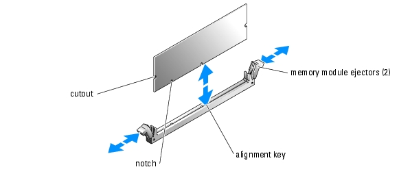
- Align the memory module's edge connector with the alignment key, and insert the memory
module in the connector. See Figure 6-5.
The memory module connector has an alignment key that allows the memory module to be installed in the connector in only one way.
- Press down on the memory module with your thumbs while pulling up on the ejectors with
your index fingers to lock the memory module into the connector. See Figure 6-5.
When the memory module is properly seated in the connector, the memory module ejectors should align with the ejectors on the other connectors with memory modules installed.
- Repeat step 6 through step 9 of this procedure to install the remaining memory modules.
- Install the cooling shroud. See "Installing the Cooling Shroud."
- Install the cover. See "Replacing the Cover" in "Troubleshooting Your System."
- Stand the system upright.
- Install the bezel. See "Installing the Bezel" in "Troubleshooting Your System."
- Perform step 11 through step 14 of the procedure in "Performing a Memory Upgrade."
Removing Memory Modules
|
|
CAUTION: See your System Information Guide for complete information about safety precautions working inside the computer and protecting against electrostatic discharge. |
- Turn off the system, including any attached peripherals, and disconnect the system from the
electrical outlet.
- Remove the bezel. See "Removing the Bezel" in "Troubleshooting Your System."
- Lay the system on its right side.
- Remove the cover. See "Removing the Cover" in "Troubleshooting Your System."
- Remove the cooling shroud. See "Removing the Cooling Shroud."
- Locate the memory module connectors from which you will remove memory modules. See
Figure A-3.
- Press down and outward on the memory module connector ejectors until the memory module
pops out of the connector. See Figure 6-5.
- Repeat step 6 and step 7 of this procedure to remove any other memory modules.
- Install the cooling shroud. See "Installing the Cooling Shroud."
- Install the cover. See "Replacing the Cover" in "Troubleshooting Your System."
- Stand the system upright.
- Install the bezel. See "Installing the Bezel" in "Troubleshooting Your System."
- Perform step 11 through step 14 of the procedure in "Performing a Memory Upgrade."
Processor
To take advantage of future options in speed and functionality, you can upgrade the processor.
The processor and its associated cache memory are contained in a PGA package that is installed in a ZIF socket on the system board.
The following items are included in the processor upgrade kit:
Replacing the Processor
|
|
CAUTION: See your System Information Guide for complete information about safety precautions working inside the computer and protecting against electrostatic discharge. |
- Turn off the system, including any attached peripherals, and disconnect the system from the
electrical outlet.
- Remove the bezel. See "Removing the Bezel" in "Troubleshooting Your System."
- Lay the system on its right side.
- Remove the cover. See "Removing the Cover" in "Troubleshooting Your System."
- Remove the cooling shroud. See "Removing the Cooling Shroud."
 |
NOTICE: The processor and heat sink can become extremely hot. Allow sufficient time for the processor
and heat sink to cool before handling.
|
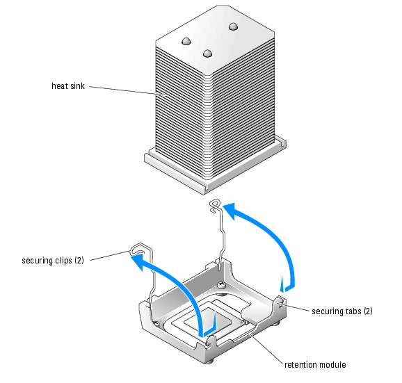
- Remove the heat sink. See Figure 6-6 and Figure 6-7.
 |
NOTE: Remove the heat sink while the processor is still warm.
|
- Remove one securing clip by pressing the tab on the clip until it clears the securing tab on
the retention module, and then lift the clip up.
- Repeat step a for the remaining securing clip.
- Rotate the heat sink slightly and then lift the heat sink off the processor. Do not pry the
processor off the heat sink.
Figure 6-6. Removing the Heat Sink (Low Profile)
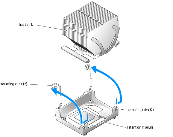
Figure 6-7. Removing the Heat Sink (High Profile)
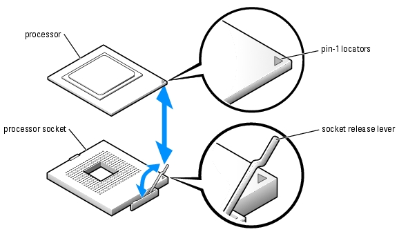
- Pull the socket release lever upward to the fully open position. See Figure 6-8.
|
NOTICE: Be careful not to bend any of the pins when removing the processor. Bending the pins can
permanently damage the processor.
|
- Lift the processor out of the socket and leave the release lever in the open position so that the
socket is ready for the new processor. See Figure 6-8.
Figure 6-8. Replacing the Processor
- Unpack the new processor and heat sink.
If any of the pins on the processor appear bent, see "Getting Help" for instructions on obtaining technical assistance.
- Ensure that the processor socket release lever is in the fully open position.
- Align pin 1 on the processor (see Figure 6-8) with pin 1 on the processor socket.
|
NOTE: No force is needed to install the processor in the socket. When the processor is aligned
correctly, it should drop into the socket.
|
- Carefully install the processor in the socket and press it down lightly to seat it. See Figure 6-8.
|
NOTICE: Positioning the processor incorrectly can permanently damage the processor and the system
when you turn on the system. When placing the processor in the socket, be sure that all of the pins on the
processor go into the corresponding holes. Be careful not to bend the pins.
|
- When the processor is fully seated in the socket, rotate the socket release lever back down
until it snaps into place, securing the processor in the socket.
|
NOTICE: Do not operate the system without the heat sink installed. The heat sink is required to maintain
proper thermal conditions.
|
- Remove the thermal grease protective cover from the new heat sink.
If you did not receive a new heat sink with the processor, see "Getting Help."
|
NOTICE: If you are installing a heat sink with external cooling pipes, install the heat sink with the cooling
pipes pointing towards the center of the system.
|
- Lower the heat sink onto the processor. See Figure 6-6 and Figure 6-7.
- Secure the heat sink to the retention module.
- Gently press down on the heat sink and then press one securing clip to secure it.
- Repeat step a for the remaining securing clip.
- Ensure that the back fan connector is connected to the BACK_FAN connector on the system
board. See Figure 6-4 and Figure A-3.
- Install the cooling shroud. See "Installing the Cooling Shroud.
- Install the cover. See "Replacing the Cover" in "Troubleshooting Your System."
- Stand the system upright.
- Install the bezel. See "Installing the Bezel" in "Troubleshooting Your System."
- Reconnect the system to its electrical outlet and turn the system on, including any attached
peripherals.
- Enter the System Setup program, and ensure that the processor options match the new
system configuration. See "Using the System Setup Program" in your User's Guide.
As the system boots, it detects the presence of the new processor and automatically changes the system configuration information in the System Setup program. A message similar to the following appears:
One 2.3 GHz Processor, Processor Bus: 400 MHz, L2 cache 128 KB
Advanced
- Confirm that the top line of the system data area in the System Setup program correctly
identifies the installed processor(s). See "Using the System Setup Program" in your User's
Guide.
- Exit the System Setup program.
- Ensure that your system is running the latest BIOS version.
You can download the latest BIOS version from the Dell Support website located at support.dell.com
- Run the system diagnostics to verify that the new processor is operating correctly.
See "Running the System Diagnostics" for information on running the diagnostics and troubleshooting any problems that may occur.
Expansion Cards
The system supports up to five PCI expansion cards, which are installed in PCI slot connectors. Slots 1 and 2 supports PCI 32-bit, 33-MHz, 5.0-V expansion cards and slots 3, 4, and 5 support PCI-X 64-bit, 66-MHz, 3.3-V expansion cards. See Figure A-3 to identify the expansion slots.
If you install a RAID controller card, it must be installed in slot 3, 4, or 5. If you install both a RAID controller card and an Ultra3 SCSI controller card, install the RAID controller card in PCI slot 5.
Installing an Expansion Card
|
|
CAUTION: See your System Information Guide for complete information about safety precautions working inside the computer and protecting against electrostatic discharge. |
- Unpack the expansion card, and prepare it for installation.
For instructions, see the documentation that accompanied the card.
- Turn off the system, including any attached peripherals, and disconnect the system from the
electrical outlet.
- Remove the bezel. See "Removing the Bezel" in "Troubleshooting Your System."
- Lay the system on its right side.
- Remove the cover. See "Removing the Cover" in "Troubleshooting Your System."
- Remove the filler bracket from the expansion slot.
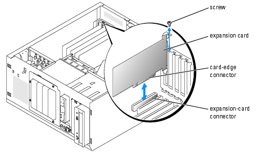
- Install the expansion card. See Figure 6-9.
- Position the expansion card so that the card-edge connector aligns with the expansion-
card connector on the system board.
- Insert the card-edge connector firmly into the expansion-card connector until the card is
fully seated.
- Install the screw that secures the expansion-card bracket to the back panel.
- Connect any cables that should be attached to the card.
See the documentation that accompanied the card for information about its cable connections.
- Install the cover. See "Replacing the Cover" in "Troubleshooting Your System."
- Stand the system upright.
- Install the bezel. See "Installing the Bezel" in "Troubleshooting Your System."
- Reconnect the system to its electrical outlet and turn the system on, including any attached
peripherals.
- Install any device drivers required for the card as described in the documentation for the card.
Figure 6-9. Removing and Installing an Expansion Card
Removing an Expansion Card
|
|
CAUTION: See your System Information Guide for complete information about safety precautions working inside the computer and protecting against electrostatic discharge. |
- Turn off the system, including any attached peripherals, and disconnect the system from the
electrical outlet.
- Remove the bezel. See "Removing the Bezel" in "Troubleshooting Your System."
- Lay the system on its right side.
- Remove the cover. See "Removing the Cover" in "Troubleshooting Your System."
- Disconnect any cables attached to the card.
- Remove the expansion card (see Figure 6-9):
- Remove the screw that secures the expansion-card bracket to the back panel.
- Grasp the expansion card by its top corners, and carefully remove it from the expansion-
card connector.
|
NOTICE: You must install a filler bracket over an empty expansion slot to maintain Federal
Communications Commission (FCC) certification of the system. The brackets also help keep dust and dirt
out of the system and aid in proper cooling and airflow inside the system.
|
- If you are removing the card permanently, install a metal filler bracket over the empty
expansion slot opening and close the expansion-card latch.
- Install the cover. See "Replacing the Cover" in "Troubleshooting Your System."
- Stand the system upright.
- Install the bezel. See "Installing the Bezel" in "Troubleshooting Your System."
- Reconnect the system to its electrical outlet and turn the system on, including any attached
peripherals.
System Battery
The system battery is a 3.0-volt (V), coin-cell battery.
Replacing the System Battery
|
|
CAUTION: See your System Information Guide for complete information about safety precautions working inside the computer and protecting against electrostatic discharge. |
|
|
CAUTION: There is a danger of a new battery exploding if it is incorrectly installed. Replace the battery only with the same or equivalent type recommended by the manufacturer. Discard used batteries according to the manufacturer's instructions. See your System Information Guide for additional information. |
- Turn off the system, including any attached peripherals, and disconnect the system from the
electrical outlet.
- Remove the bezel. See "Removing the Bezel" in "Troubleshooting Your System."
- Lay the system on its right side.
- Remove the cover. See "Removing the Cover" in "Troubleshooting Your System."
- Remove the expansion card(s) in slot 1 and slot 2 (if applicable). See "Removing an
Expansion Card."
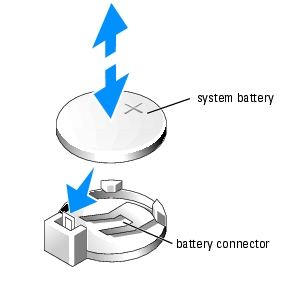
- Remove the system battery. See Figure 6-10.
See Figure A-3 to locate the system battery on the system board.
You can pry the system battery out of its connector with your fingers or with a blunt, nonconductive object such as a plastic screwdriver.
- Install the new system battery with the side labeled "+" facing up. See Figure 6-10.
Figure 6-10. Replacing the System Battery
- Install the expansion card(s) in slot 1 and slot 2 (if applicable). See "Installing an Expansion
Card."
- Replace the cover. See "Replacing the Cover" in "Troubleshooting Your System."
- Stand the system upright.
- Install the bezel. See "Installing the Bezel" in "Troubleshooting Your System."
- Reconnect the system to its electrical outlet and turn the system on, including any attached
peripherals.
- Enter the System Setup program to confirm that the battery is operating properly. See "Using
the System Setup Program" in your User's Guide.
- Enter the correct time and date in the System Setup program's Time and Date fields.
- Exit the System Setup program.
- To test the newly installed battery, turn off the system and disconnect it from the electrical
outlet for at least an hour.
- After an hour, reconnect the system to its electrical outlet and turn it on.
- Enter the System Setup program and if the time and date are still incorrect, see "Getting
Help" for instructions on obtaining technical assistance.
Back to Contents Page