 Processor Cooling Shrouds
Dell™ PowerEdge™ SC1420 Systems Installation and Troubleshooting Guide
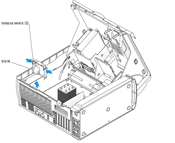
Processor Cooling Shroud Blank
This section describes how to install the following system components:
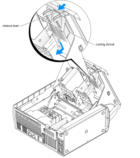
Your system contains up to two processor cooling shrouds with fans to direct air flow over the processor(s). If your system contains two processor cooling shrouds, you must remove the cooling shroud for CPU_1 before you can remove the cooling shroud for CPU_0.
If only one processor is installed (CPU_0), a fan blank must be installed in place of the CPU_1 fan to maintain proper cooling.

|
CAUTION: Only trained service technicians are authorized to open the system cover and access any of the components inside the system. See your System Information Guide for complete information about safety precautions, working inside the computer, and protecting against electrostatic discharge. |
 |
NOTICE: To avoid damaging the fan power cables, do not remove the shroud too quickly. |
 |
NOTE: If there are two processor cooling shrouds installed, you must remove the CPU_1 cooling shroud first. |
If only one processor cooling shroud is installed, disconnect the fan's power cable for CPU_0 from the system board. Proceed to step 5.
Figure 6-1. Removing and Installing the Processor Cooling Shrouds

|
|
CAUTION: Only trained service technicians are authorized to open the system cover and access any of the components inside the system. See your System Information Guide for complete information about safety precautions, working inside the computer, and protecting against electrostatic discharge. |
|
NOTE: When two processor cooling shrouds are installed, the cooling shroud for CPU_0 must be installed first. |
The processor cooling shroud blank is used when only one processor is installed. The blank must be installed in place of the CPU_1 cooling shroud to maintain proper cooling.
|
|
CAUTION: Only trained service technicians are authorized to open the system cover and access any of the components inside the system. See your System Information Guide for complete information about safety precautions, working inside the computer, and protecting against electrostatic discharge. |
Figure 6-2. Removing and Installing the Processor Cooling Shroud Blank
.
|
|
CAUTION: Only trained service technicians are authorized to open the system cover and access any of the components inside the system. See your System Information Guide for complete information about safety precautions, working inside the computer, and protecting against electrostatic discharge. |
The expansion card fan is part of the expansion card cooling shroud. The fan and shroud are replaced as a unit.
|
|
CAUTION: Only trained service technicians are authorized to open the system cover and access any of the components inside the system. See your System Information Guide for complete information about safety precautions, working inside the computer, and protecting against electrostatic discharge. |
Figure 6-3. Removing and Installing the Expansion Card Cooling Shroud
.
The system supports up to six half-length PCI expansion cards (three 64-bit, 100-MHz PCI-X, two 2.5-GHz PCI Express, and one 32-bit, 33-MHz). See Figure A-3 for the location of the expansion card slots.
|
|
CAUTION: Only trained service technicians are authorized to open the system cover and access any of the components inside the system. See your System Information Guide for complete information about safety precautions, working inside the computer, and protecting against electrostatic discharge. |
Figure 6-4. Installing an Expansion Card

|
NOTE: Keep this bracket in case you need to remove the expansion card. Filler brackets must be installed over empty expansion-card slots to maintain Federal Communications Commission (FCC) certification of the system. The brackets also keep dust and dirt out of the system and aid in proper cooling and airflow inside the system. |
See the documentation that came with the card for information on configuring the card, making internal connections, or otherwise customizing it for your system.
|
NOTE: Some NICs automatically start the system when they are connected to a network. |
|
NOTICE: Do not route card cables over or behind the cards. Cables routed over the cards can prevent the system cover from closing properly or cause damage to the equipment. |
See the documentation for the card for information about the card's cable connections.
|
|
CAUTION: Only trained service technicians are authorized to open the system cover and access any of the components inside the system. See your System Information Guide for complete information about safety precautions, working inside the computer, and protecting against electrostatic discharge. |
|
NOTE: Filler brackets must be installed over empty expansion card slots to maintain FCC certification of the system. The brackets also keep dust and dirt out of the system and aid in proper cooling and airflow inside the system. |
See Figure A-3 for the location of the six memory module connectors. The six memory module connectors on the system board can accommodate from 256 MB to 12 GB of 400-MHz registered ECC DDR II memory modules.
The system is upgradable to 12 GB by installing combinations of 256-MB, 512-MB, 1-GB, or 2-GB 400-MHz registered ECC DDR II memory modules. You can purchase memory upgrade kits from Dell.
|
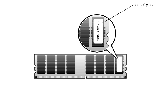
NOTE: Dual-ranked memory modules with less capacity take precedence over single-ranked memory modules with greater capacity. |
Figure 6-5. Determining the Memory Module's Capacity and Rank
|
NOTICE: If you remove your original memory modules from the system during a memory upgrade, keep them separate from any new memory modules that you may have, even if you purchased the new memory modules from Dell. Use only registered ECC DDR II memory modules. |
Table 6-1 illustrates sample memory configurations. The configurations shown do not indicate dual-ranked memory modules. See "Memory Module Installation Guidelines" for detailed information.
Table 6-1. Sample Memory Configurations
|
Total Memory |
DIMM_1 |
DIMM_2 |
DIMM_3 |
DIMM_4 |
DIMM_5 |
DIMM_6 |
|---|---|---|---|---|---|---|
Your system supports a maximum of 4 GB of memory using four 1-GB memory modules. Current operating systems can use a maximum of 4 GB of address space; however, the amount of memory available to the operating system is slightly less than 4 GB. Certain components within the system require address space in the 4-GB range. Any address space reserved for these components cannot be used by system memory.
The following components require address space:
At start-up, the BIOS identifies the components that require address space. The BIOS dynamically calculates the amount of reserved address space required. The BIOS then subtracts the reserved address space from 4 GB to determine the amount of usable space.
|
|
CAUTION: Only trained service technicians are authorized to open the system cover and access any of the components inside the system. See your System Information Guide for complete information about safety precautions, working inside the computer, and protecting against electrostatic discharge. |
The memory module connector has an alignment key that allows the memory module to be installed in the connector in only one way.
Figure 6-6. Installing a Memory Module
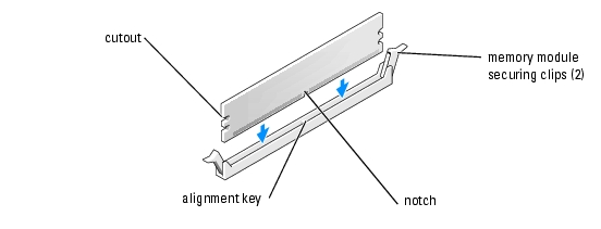
If you insert the module correctly, the securing clips snap into the cutouts at each end of the module.
When the memory module is properly seated in the connector, the securing clips on the memory module socket should align with the securing clips on the other connectors with memory modules installed.
The system detects that the new memory does not match the existing configuration information and generates the following message:
The amount of system memory has changed.
Strike the F1 key to continue, F2 to run the setup utility
The system should have changed the value for Memory Info to reflect the newly installed memory. Verify the new value. If it is correct, skip to step 13.
|
|
CAUTION: Only trained service technicians are authorized to open the system cover and access any of the components inside the system. See your System Information Guide for complete information about safety precautions, working inside the computer, and protecting against electrostatic discharge. |
If the module is difficult to remove, gently move the module back and forth to remove it from the connector.
To take advantage of future options in speed and functionality, you can upgrade to a second processor or replace either the primary or secondary processor.
|
NOTE: If two processors are installed, they must be identical (speed, type, and cache). |
Each processor and its associated cache memory are contained in a PGA package that is installed in a ZIF socket on the system board.
|
|
CAUTION: Only trained service technicians are authorized to open the system cover and access any of the components inside the system. See your System Information Guide for complete information about safety precautions, working inside the computer, and protecting against electrostatic discharge. |
|
|
CAUTION: The processor and heat sink can get very hot during normal operation. Ensure that they have had sufficient time to cool before you touch them. |
|
NOTE: If two processors are installed, CPU_0 must be removed before removing CPU_1. |
|
NOTE: If you are removing the CPU_1 heat sink, remove the VRM before removing the heat sink. See "Removing the VRM." |
Figure 6-7. Removing the Retention Module Clip
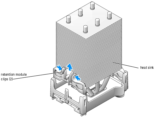
Figure 6-8. Removing and Installing the Heat Sink
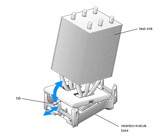
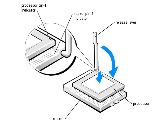
Figure 6-9. Removing the Processor

|
NOTICE: Be careful not to bend any of the pins when you remove the processor from the socket. Bending the pins can permanently damage the processor. |
If you are replacing the processor, leave the release lever in the release position so that the socket is ready for the new processor and go to "Installing a Processor."
While squeezing the tabs on retention module clip, lower the clip into the retention module base until it snaps into place. See Figure 6-7. Repeat this step for the second retention module clip.
|
|
CAUTION: Only trained service technicians are authorized to open the system cover and access any of the components inside the system. See your System Information Guide for complete information about safety precautions, working inside the computer, and protecting against electrostatic discharge. |
|
NOTICE: Processor pins are delicate. To avoid damage, ensure that the processor aligns properly with the socket, and do not use excessive force when you install the processor. |
Figure 6-10. Installing the Processor
Repeat this step for the second retention module clip.
If you are replacing a processor, replace the processor cooling shroud. See "Installing the Processor Cooling Shrouds."
|
|
CAUTION: Only trained service technicians are authorized to open the system cover and access any of the components inside the system. See your System Information Guide for complete information about safety precautions, working inside the computer, and protecting against electrostatic discharge. |
|
NOTICE: Remove the VRM before you remove the CPU_1 processor. |
If the system is operating in a single processor mode, continue to the next step.
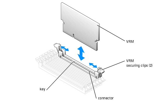
Figure 6-11. Removing and Installing the VRM
|
|
CAUTION: Only trained service technicians are authorized to open the system cover and access any of the components inside the system. See your System Information Guide for complete information about safety precautions, working inside the computer, and protecting against electrostatic discharge. |
|
NOTICE: A VRM must be installed to operate the system with two processors. See Figure A-3 for the location of the VRM connector. |
The VRM connector has an alignment key that allows the VRM to be installed in the connector in only one way.
If you insert the VRM correctly, the securing clips snap into the cutouts at each end of the VRM.
A coin-cell battery maintains system configuration, date, and time information. The battery can last several years.
If you have to repeatedly reset time and date information after turning on the computer, replace the battery.
The battery may need replacing if you have repeatedly reset the time and date information after turning on the system or if one of the following messages appear:
Time-of-day not set - please run SETUP program
or
Invalid configuration information -
please run SETUP program
To determine whether you need to replace the battery, see "Troubleshooting the System Battery" in "Troubleshooting Your System."
You can operate your system without a battery; however, without a battery, the configuration information is erased if the system is turned off or unplugged from the electrical outlet. In this case, you must enter the System Setup program and reset the configuration options.
|
|
CAUTION: A new battery can explode if it is incorrectly installed. Replace the battery only with the same or equivalent type recommended by the manufacturer. Discard used batteries according to the manufacturer's instructions. |
|
|
CAUTION: Only trained service technicians are authorized to open the system cover and access any of the components inside the system. See your System Information Guide for complete information about safety precautions, working inside the computer, and protecting against electrostatic discharge. |
|
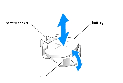
NOTICE: If you use a blunt, nonconductive object to depress the tab next to the battery, be careful not to touch the system board with the object. Ensure that the object is inserted between the battery and the tab before you attempt to depress the tab. Do not pry out the battery. You may damage the system board by prying off the socket or by breaking circuit traces on the system board. |
Figure 6-12. Replacing the Battery
Also, re-enter any system configuration information that is no longer displayed on the System Setup screens, and then exit the System Setup program.