Back to Contents Page
Troubleshooting Your System
Dell™ PowerEdge™ SC1420 Systems Installation and Troubleshooting Guide
 Safety First—For You and Your System
Start-Up Routine
Opening the System
Closing the System
Checking the Equipment
Inside the System
Troubleshooting a Wet System
Troubleshooting a Damaged System
Troubleshooting the System Battery
Troubleshooting System Cooling Problems
Troubleshooting System Memory
Troubleshooting a Diskette Drive
Troubleshooting a CD Drive
Troubleshooting a SCSI Hard Drive
Troubleshooting a SATA Hard Drive
Troubleshooting a Hard Drive in a RAID Configuration
Troubleshooting a RAID Controller Card
Troubleshooting Expansion Cards
Troubleshooting the Processors
Safety First—For You and Your System
To perform certain procedures in this document, you must remove the system cover and work inside the system. While working inside the system, do not attempt to service the system except as explained in this guide and elsewhere in your system documentation.

|
CAUTION: Only trained service technicians are authorized to open the system cover and access any of the components inside the system. See your System Information Guide for complete information about safety precautions, working inside the computer, and protecting against electrostatic discharge. |
Start-Up Routine
Look and listen during the system's start-up routine for the indications described in Table 5-1.
Table 5-1. Start-Up Routine Indications
Opening the System
|
|
CAUTION: Only trained service technicians are authorized to open the system cover and access any of the components inside the system. See your System Information Guide for complete information about safety precautions, working inside the computer, and protecting against electrostatic discharge. |
- Turn off the system and attached peripherals, and disconnect the system from the electrical
outlet.
- Press the power button to ground the system board.
- If you have installed a padlock through the padlock ring on the back panel, remove the
padlock.
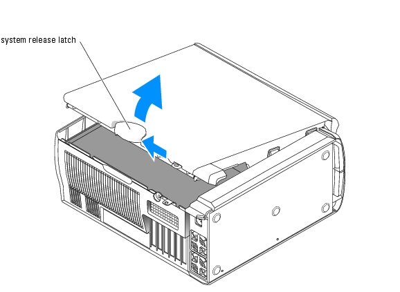
- Lay the system on its side as shown in Figure 5-1.
 |
NOTICE: Ensure that sufficient space exists to accommodate the open cover—at least 30 cm (1 ft) of
desktop space.
|
- Open the system by sliding the cover release latch and rotating the cover open as shown in
Figure 5-1.
Closing the System
- Ensure that all cables are connected, and fold cables out of the way.
- Ensure that no tools or extra parts are left inside the system.
- Close the system cover.
- Rotate the cover down. See Figure 5-1.
- Press down on the cover until the cover release latch is fully engaged.
- If applicable, install the padlock.
- Reconnect the system to the electrical outlet, and turn on the system and attached
peripherals.
After you open and close the cover, the chassis intrusion detector, if enabled, causes the following message to appear on the screen at the next computer start-up:
ALERT! Cover was previously removed.
- Reset the chassis intrusion detector by changing Chassis Intrusion to Enabled or Enabled-
Silent. See your User's Guide for details.
 |
NOTE: If a setup password has been assigned by someone else, contact your network
administrator for information on resetting the chassis intrusion detector.
|
Figure 5-1. Opening and Closing the System
Checking the Equipment
This section provides troubleshooting procedures for external devices attached to the system, such as the monitor, keyboard, or mouse. Before you perform any of the procedures, see "Troubleshooting External Connections."
Troubleshooting External Connections
Loose or improperly connected cables are the most likely source of problems for the system, monitor, and other peripherals (such as a printer, keyboard, mouse, or other external device). Ensure that all external cables are securely attached to the external connectors on your system. See Figure 2-2 for the back-panel connectors and Figure 2-1 for the front-panel connectors on your system.
Troubleshooting the Video Subsystem
Problem
- Monitor is not working properly.
- Video memory is faulty.
- Video card is faulty.
Action
- Check the system and power connections to the monitor.
- Turn off the system and attached peripherals, and disconnect the system from the electrical
outlet.
- Open the system. See "Opening the System."
- Ensure that the video card is properly installed. See "Expansion Cards" in "Installing System
Components."
- Close the system. See "Closing the System."
- Run the appropriate online diagnostic test. See "Using Server Administrator Diagnostics" in
"Running System Diagnostics."
If the tests run successfully, the problem is not related to video hardware. See "Finding Software Solutions."
If the tests fail, see "Getting Help."
Troubleshooting the Keyboard
Problem
- System message indicates a problem with the keyboard.
- Keyboard is not functioning properly.
Action
- Run the appropriate online diagnostic test. See "Using Server Administrator Diagnostics" in
"Running System Diagnostics."
- Press each key on the keyboard, and examine the keyboard and its cable for signs of damage.
- Swap the faulty keyboard with a working keyboard.
If the problem is resolved, replace the faulty keyboard. See "Getting Help."
If the problem is not resolved, see "Getting Help."
Troubleshooting the Mouse
Problem
- System message indicates a problem with the mouse.
- Mouse is not functioning properly.
Action
- Run the appropriate online diagnostic test. See "Using Server Administrator Diagnostics" in
"Running System Diagnostics."
If the test fails, continue to the next step.
- Examine the mouse and its cable for signs of damage.
If the mouse is not damaged, go to step 4.
If the mouse is damaged, continue to the next step.
- Swap the faulty mouse with a working mouse.
If the problem is resolved, replace the faulty mouse. See "Getting Help."
- Enter the System Setup program and ensure that the mouse controller is enabled. See "Using
the System Setup Program" in your User's Guide.
If the problem is not resolved, see "Getting Help."
Troubleshooting Basic I/O Functions
Problem
- Error message indicates a problem with a serial or parallel port.
- Device connected to a serial or parallel port is not operating properly.
Action
- Enter the System Setup program and ensure that the serial port(s) and parallel port are
enabled. See "Using the System Setup Program" in the User's Guide.
- If the problem is confined to a particular application, see the application documentation for
specific port configuration requirements that the program may require.
- Run the appropriate online diagnostic test. See "Using Server Administrator Diagnostics" in
"Running System Diagnostics."
If the tests run successfully but the problem persists, see the appropriate procedure—"Troubleshooting a Serial I/O Device" or "Troubleshooting a Parallel Printer."
Troubleshooting a Serial I/O Device
Problem
- Device connected to the serial port is not operating properly.
Action
- Turn off the system and any peripheral devices connected to the serial port.
- Swap the serial interface cable with a working cable, and turn on the system and the serial
device.
If the problem is resolved, replace the interface cable. See "Getting Help."
- Turn off the system and the serial device, and swap the device with a comparable device.
- Turn on the system and the serial device.
If the problem is resolved, replace the serial device. See "Getting Help."
If the problem persists, see "Getting Help."
Troubleshooting a Parallel Printer
Problem
- Device connected to the parallel port is not operating properly.
Action
- Turn off the system and any peripheral devices connected to the parallel port.
- Swap the printer interface cable with a working cable, and turn on the system and the printer.
If the problem is resolved, replace the interface cable. See "Getting Help."
- Turn off the system and the printer, and swap the printer with a comparable printer.
- Turn on the system and the printer.
If the problem is resolved, replace the printer. See "Getting Help."
If the problem persists, see "Getting Help."
Troubleshooting a USB Device
Problem
- System message indicates a problem with a USB device.
- Device connected to a USB port is not operating properly.
Action
- Enter the System Setup program, and ensure that the USB ports are enabled. See "Using the
System Setup Program" in your User's Guide.
- Turn off the system and any USB devices.
- Disconnect the USB devices, and connect the malfunctioning device to the other USB
connector.
- Turn on the system and the reconnected device.
If the problem is resolved, the USB connector might be defective. See "Getting Help."
- If possible, swap the interface cable with a working cable.
If the problem is resolved, replace the interface cable. See "Getting Help."
- Turn off the system and the USB device, and swap the device with a comparable device.
- Turn on the system and the USB device.
If the problem is resolved, replace the USB device. See "Getting Help."
If the problem persists, see "Getting Help."
Troubleshooting a NIC
Problem
- NIC cannot communicate with network.
Action
- Run the appropriate online diagnostic test. See "Using Server Administrator Diagnostics" in
"Running System Diagnostics."
- Check the appropriate indicator on the NIC connector. See Table 2-3 in "Indicators,
Messages, and Codes."
- If the link indicator does not light, check all cable connections.
- If the activity indicator does not light, the network driver files might be damaged or missing.
Remove and reinstall the drivers if applicable. See the NIC's documentation.
- Change the autonegotiation setting, if possible.
- Use another connector on the switch or hub.
If you are using a NIC card instead of an integrated NIC, see the documentation for the NIC card.
- Ensure that the appropriate drivers are installed and the protocols are bound. See the NIC's
documentation.
- Enter the System Setup program and confirm that the NICs are enabled. See "Using the
System Setup Program" in your User's Guide.
- Ensure that the NICs, hubs, and switches on the network are all set to the same data
transmission speed. See the network equipment documentation.
- Ensure that all network cables are of the proper type and do not exceed the maximum length.
See "Network Cable Requirements" in your User's Guide.
Inside the System
In Figure 5-2, the system cover is opened to provide an interior view of the system.
Figure 5-2. Inside the System
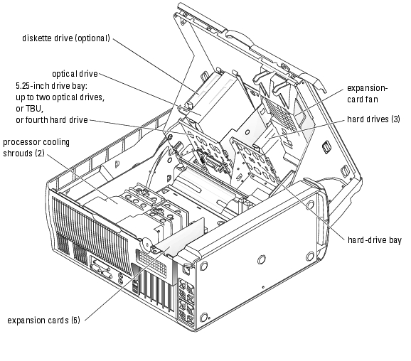
The system board can accommodate up to two processors, six expansion cards (three 64-bit, 100-MHz PCI-X, two 2.5-GHz PCI-Express, and one 32-bit, 33-MHz), and six 400-MHz DDR II SDRAM memory modules upgradable to 12 GB.
The drive bays provide space for up to four 1-inch SATA (up to two SATA drives with the integrated SATA controller and up to four SATA drives with a SATA controller card) or SCSI hard drives. The SCSI hard drives must be connected to a controller card. They also provide space for two optical drives, an optional diskette drive, and an optional tape backup unit (TBU). Power is supplied to the system board and internal peripherals through a single nonredundant power supply.
Troubleshooting a Wet System
Problem
- Liquid spilled on the system.
- Excessive humidity.
Action
|
|
CAUTION: Only trained service technicians are authorized to open the system cover and access any of the components inside the system. See your System Information Guide for complete information about safety precautions, working inside the computer, and protecting against electrostatic discharge. |
- Turn off the system and attached peripherals, and disconnect the system from the electrical
outlet.
- Open the system. See "Opening the System."
- Remove all expansion cards, memory modules, and processors installed in the system. See
"Removing an Expansion Card," "Removing a Memory Module," and "Removing the
Processor" in "Installing System Components."
- Let the system dry thoroughly for at least 24 hours.
- Install the video card.
If SCSI hard drives or more than two SATA hard drives are installed, install the controller card. See "Installing an Expansion Card" in "Installing System Components."
- Close the system. See "Closing the System."
- Reconnect the system to the electrical outlet, and turn on the system and attached
peripherals.
If the system does not start properly, see "Getting Help."
- If the system starts properly, shut down the system and reinstall all of the expansion cards that
you removed. See "Installing an Expansion Card" in "Installing System Components."
- Run the appropriate online diagnostic test. See "Using Server Administrator Diagnostics" in
"Running the System Diagnostics."
If the tests fail, see "Getting Help."
Troubleshooting a Damaged System
Problem
- System was dropped or damaged.
Action
|
|
CAUTION: Only trained service technicians are authorized to open the system cover and access any of the components inside the system. See your System Information Guide for complete information about safety precautions, working inside the computer, and protecting against electrostatic discharge. |
- Open the system. See "Opening the System."
- Ensure that the following components are properly installed:
- Expansion card(s)
- Processors(s)
- Memory modules
- Hard drives, optical drives, and TBU
- Fans
- VRM
- Ensure that all cables are properly connected.
- Close the system. See "Closing the System."
- Run the system board tests in the system diagnostics. See "Running System Diagnostics."
If the tests fail, see "Getting Help."
Troubleshooting the System Battery
Problem
- System message indicates a problem with the battery.
- System Setup program loses system configuration information.
- System date and time do not remain current.
|
NOTE: If the system is turned off for long periods of time (for weeks or months), the NVRAM may lose its
system configuration information. This situation is caused by a defective battery.
|
Action
- Re-enter the time and date through the System Setup program. See "Using the System Setup
Program" in your User's Guide.
- Turn off the system and disconnect it from the electrical outlet for at least one hour.
- Reconnect the system to the electrical outlet and turn on the system.
- Enter the System Setup program.
If the date and time are not correct in the System Setup program, replace the battery. See "System Battery" in "Installing System Components."
If the problem is not resolved by replacing the battery, see "Getting Help."
|
NOTE: Some software may cause the system time to speed up or slow down. If the system seems to
operate normally except for the time kept in the System Setup program, the problem may be caused by
software rather than by a defective battery.
|
Troubleshooting System Cooling Problems
Problem
- System issues a fan-related or thermal failure error message.
Action
Ensure that none of the following conditions exist:
- Ambient temperature is too high.
- External airflow is obstructed.
- Cables inside the system obstruct airflow.
- Processor heat sinks are not installed properly. See "Processor" in "Installing System Components."
- An individual cooling fan is not installed properly or has failed. See "Troubleshooting Fans."
Troubleshooting Fans
Problem
- A fan-related error message.
Action
|
|
CAUTION: Only trained service technicians are authorized to open the system cover and access any of the components inside the system. See your System Information Guide for complete information about safety precautions, working inside the computer, and protecting against electrostatic discharge. |
- Run the appropriate diagnostic test. See "Using Server Administrator Diagnostics" in
"Running System Diagnostics."
- Turn off the system and attached peripherals, and disconnect the system from the electrical
outlet.
- Open the system. See "Opening the System."
- Ensure that the faulty fan's power cable is firmly attached to the system board connector. See
Figure A-3.
- Close the system. See "Closing the System."
- Reconnect the system to the electrical outlet, and turn on the system and attached
peripherals.
- If the problem is not resolved, install the appropriate new fan. See "Installing the Processor
Cooling Shrouds" or "Installing the Expansion Card Fan" in "Installing System Components."
If the replacement fan does not operate, see "Getting Help."
Troubleshooting System Memory
Problem
- Error message during POST.
- Faulty memory module.
- Faulty system board.
Action
|
|
CAUTION: Only trained service technicians are authorized to open the system cover and access any of the components inside the system. See your System Information Guide for complete information about safety precautions, working inside the computer, and protecting against electrostatic discharge. |
- Run the appropriate online diagnostic test. See "Using Server Administrator Diagnostics" in
"Running System Diagnostics."
- Turn off the system and attached peripherals, and disconnect the system from the electrical
outlet.
- Open the system. See "Opening the System."
- Ensure that the memory modules are proper installed. See "Memory Module Installation
Guidelines" and "Installing a Memory Module" in "Installing System Components."
- Remove all of the memory modules. See "Removing a Memory Module" in "Installing System
Components."
|
NOTE: Record the DIMM socket so that the memory modules can be properly reinstalled in step 9.
|
- Install the suspected faulty memory module in DIMM_1.
- Close the system. See "Closing the System."
- Reconnect the system to the electrical outlet, and turn on the system and attached
peripherals.
If no memory errors occur during POST, repeat step 2 and step 3, and step 6 through step 8 for all the suspected faulty memory modules.
If memory errors occur, replace the faulty memory modules.
- Reinstall the memory modules. See "Installing a Memory Module" in "Installing System
Components."
- Close the system. See "Closing the System."
- Reconnect the system to the electrical outlet, and turn on the system and attached
peripherals.
- Enter the System Setup program and check the system memory setting. See "Using the
System Setup Program" in your User's Guide.
If the problem persists, see "Getting Help."
Troubleshooting a Diskette Drive
Problem
- Error message indicates a diskette drive problem.
Action
|
|
CAUTION: Only trained service technicians are authorized to open the system cover and access any of the components inside the system. See your System Information Guide for complete information about safety precautions, working inside the computer, and protecting against electrostatic discharge. |
- Enter the System Setup program and verify that the diskette drive is configured correctly. See
"Using the System Setup Program" in the User's Guide.
- Run the appropriate online diagnostic test. See "Using Server Administrator Diagnostics" in
"Running System Diagnostics."
- Turn off the system and attached peripherals, and disconnect the system from the electrical
outlet.
- Open the system. See "Opening the System."
- Ensure that the diskette drive interface cable is securely connected to the diskette drive and
the system board. See Figure A-3.
- Ensure that a power cable is properly connected to the drive.
- Close the system. See "Closing the System."
- Reconnect the system to the electrical outlet, and turn on the system and attached
peripherals.
- Run the appropriate online diagnostic test to see whether the diskette drive works correctly.
- Turn off the system and attached peripherals, and disconnect the system from its electrical
outlet.
- Open the system. See "Opening the System."
- Remove all expansion cards installed in the system (except the video card). See "Removing an
Expansion Card" in "Installing System Components."
- Close the system. See "Closing the System."
- Reconnect the system to the electrical outlet, and turn on the system and attached
peripherals.
- Run the appropriate online diagnostic test to see whether the diskette drive works correctly.
If the tests run successfully, an expansion card may be conflicting with the diskette drive logic, or an expansion card may be faulty. Continue to the next step.
If the tests fail, see "Getting Help."
- Turn off the system and attached peripherals, and disconnect the system from the electrical
outlet.
- Open the system. See "Opening the System."
- Reinstall one of the expansion cards you removed in step 12. See "Installing an Expansion
Card" in "Installing System Components."
- Close the system. See "Closing the System."
- Reconnect the system to the electrical outlet, and turn on the system and attached
peripherals.
- Run the appropriate online diagnostic test to see whether the diskette drive works correctly.
- Repeat step 16 through step 22 until all expansion cards are reinstalled or one of the
expansion cards causes the tests to fail.
If the problem is not resolved, see "Getting Help."
Troubleshooting a CD Drive
Problem
- System cannot read data from a CD drive.
- CD drive indicator does not blink during boot.
Action
|
|
CAUTION: Only trained service technicians are authorized to open the system cover and access any of the components inside the system. See your System Information Guide for complete information about safety precautions, working inside the computer, and protecting against electrostatic discharge. |
- Try using a different CD that you know works properly.
- Enter the System Setup program and ensure that the drive's IDE controller is enabled. See
"Using the System Setup Program" in the User's Guide.
- Run the appropriate online diagnostic test. See "Using Server Administrator Diagnostics" in
"Running System Diagnostics."
- Turn off the system and attached peripherals, and disconnect the system from the electrical
outlet.
- Open the system. See "Opening the System."
- Ensure that the CD interface cable is securely connected to the CD drive and to the system
board. See Figure A-3.
- Ensure that a power cable is properly connected to the drive.
- Close the system. See "Closing the System."
- Reconnect the system to the electrical outlet, and turn on the system and attached
peripherals.
If the problem is not resolved, see "Getting Help."
Troubleshooting a SCSI Hard Drive
Problem
- Device driver error.
- Hard drive not recognized by the system.
Action
|
|
CAUTION: Only trained service technicians are authorized to open the system cover and access any of the components inside the system. See your System Information Guide for complete information about safety precautions, working inside the computer, and protecting against electrostatic discharge. |
|
NOTICE: This procedure can destroy data stored on the hard drive. Before you continue, back up all files
on the hard drive.
|
- Run the appropriate online diagnostic test. See "Using Server Administrator Diagnostics" in
"Running System Diagnostics."
For information about testing the controller, see the SCSI or RAID controller's documentation.
If the tests fail, continue to the next step.
- Restart the system and enter the SCSI configuration utility.
|
NOTE: To enter the utility, press <Ctrl><a> or <Ctrl><m>, depending on the utility. See the
documentation supplied with the controller for information about the configuration utility.
|
- Ensure that the primary SCSI channel is enabled, and restart the system. See the SCSI
controller documentation.
- Ensure that the required device drivers are installed and configured correctly. See the Dell
OpenManage Server Assistant for PowerEdge SC Products CD.
- Turn off the system and attached peripherals, and disconnect the system from the electrical
outlet.
- Open the system. See "Opening the System."
- Ensure that the hard-drive interface cable is properly connected between the drive and the
controller card. See the documentation supplied with the controller card.
- If the hard drive is the boot drive, ensure that the drive is configured and connected properly.
See "Configuring the Boot Drive" in "Installing Drives."
- Ensure that a power cable is properly connected to the drive.
- Ensure that the hard drive is configured with a unique SCSI ID number and that the drive is
terminated or not terminated as appropriate. See the documentation for the hard drive.
- Close the system. See "Closing the System."
- Reconnect the system to the electrical outlet, and turn on the system and attached
peripherals.
If the problem persists, continue to the next step.
- Format and partition the hard drive. See the operating system documentation.
- If possible, restore the files to the drive.
If the problem persists, see "Getting Help."
Troubleshooting a SATA Hard Drive
Problem
- Faulty hard drive.
- Damaged or improperly connected hard-drive cables.
Action
|
|
CAUTION: Only trained service technicians are authorized to open the system cover and access any of the components inside the system. See your System Information Guide for complete information about safety precautions, working inside the computer, and protecting against electrostatic discharge. |
|
NOTICE: This troubleshooting procedure can destroy data stored on the hard drive. Before you proceed,
back up all files on the hard drive.
|
- Run the appropriate online diagnostic test. See "Using Server Administrator Diagnostics" in
"Running the System Diagnostics."
- Enter the System Setup program and verify that the system is configured correctly. See "Using
the System Setup Program" in your User's Guide.
- Turn off the system and attached peripherals, and disconnect the system from the electrical
outlet.
- Open the system. See "Opening the System."
- Ensure that the hard-drive interface cable is properly connected between the drive and the
system board or controller card.
To identify system board connectors, see Figure A-3.
To identify controller card connectors, see the documentation that accompanied the controller card.
- If the hard drive is the boot drive, ensure that the drive is configured and connected properly.
See "Configuring the Boot Drive" in "Installing Drives."
- Ensure that the power cable is properly connected to the drive.
- Close the system. See "Closing the System."
- Reconnect the system to the electrical outlet, and turn on the system and attached
peripherals.
- Format and partition the hard drive. See the operating system documentation.
- If possible, restore the files to the drive.
If the problem persists, see "Getting Help."
Troubleshooting a Hard Drive in a RAID Configuration
Problem
- Device driver error.
- Damaged or improperly connected hard-drive cables.
Action
|
|
CAUTION: Only trained service technicians are authorized to open the system cover and access any of the components inside the system. See your System Information Guide for complete information about safety precautions, working inside the computer, and protecting against electrostatic discharge. |
|
NOTICE: This troubleshooting procedure can destroy data stored on the hard drive. Before you proceed,
back up all files on the hard drive.
|
- Run the appropriate online diagnostic test. See "Using Server Administrator Diagnostics" in
"Running the System Diagnostics."
- Restart your system and enter the RAID configuration utility. See the RAID controller
documentation.
- Ensure that the required device drivers are installed and are configured correctly. See the Dell
OpenManage Server Assistant for PowerEdge SC Products CD and the RAID controller's
documentation.
- Turn off the system and attached peripherals, and disconnect the system from the electrical
outlet.
- Open the system. See "Opening the System."
- Ensure that the hard-drive interface cable is properly connected to the drive and to the system
board or RAID controller card.
To identify system board connectors, see Figure A-3.
To identify controller card connectors, see the documentation that accompanied the controller card.
- If the hard drive is the boot drive, ensure that the drive is configured and connected properly.
See "Configuring the Boot Drive" in "Installing Drives."
- Ensure that the power cable is properly connected to the drive.
- Close the system. See "Closing the System."
- Reconnect the system to the electrical outlet, and turn on the system and attached
peripherals.
If the problem persists, continue to the next step.
- Format and partition the hard drive. See the operating system documentation.
- If possible, restore the files to the drive.
If the problem persists, see "Getting Help."
Troubleshooting a RAID Controller Card
|
NOTE: When troubleshooting a RAID controller card, also see the documentation for your operating
system and the RAID controller.
|
Problem
- Error message indicates a RAID controller problem.
- RAID controller performs incorrectly or not at all.
Action
|
|
CAUTION: Only trained service technicians are authorized to open the system cover and access any of the components inside the system. See your System Information Guide for complete information about safety precautions, working inside the computer, and protecting against electrostatic discharge. |
- Run the appropriate online diagnostic test. See "Using Server Administrator Diagnostics" in
"Running the System Diagnostics."
- Turn off the system and attached peripherals, and disconnect the system from the electrical
outlet.
- Open the system. See "Opening the System."
- Ensure that the controller card is firmly seated in its connector. See "Installing a SATA or
SCSI Controller Card" in "Installing System Components."
- Ensure that the appropriate cables are firmly connected to their corresponding connectors on
the controller card.
- Close the system. See "Closing the System."
- Reconnect the system to the electrical outlet, and turn on the system and attached
peripherals.
If the problem persists, see the RAID controller's documentation for more information on troubleshooting.
Troubleshooting Expansion Cards
|
NOTE: When troubleshooting an expansion card, see the documentation for your operating system and
the expansion card.
|
Problem
- Error message indicates a problem with an expansion card.
- Expansion card performs incorrectly or not at all.
Action
|
|
CAUTION: Only trained service technicians are authorized to open the system cover and access any of the components inside the system. See your System Information Guide for complete information about safety precautions, working inside the computer, and protecting against electrostatic discharge. |
- Run the appropriate online diagnostic test. See "Using Server Administrator Diagnostics" in
"Running System Diagnostics."
- Turn off the system and attached peripherals, and disconnect the system from the electrical
outlet.
- Open the system. See "Opening the System."
- Ensure that each expansion card is firmly seated in its connector. See "Installing an Expansion
Card" in "Installing System Components."
- Close the system. See "Closing the System."
- Reconnect the system to the electrical outlet, and turn on the system and attached
peripherals.
If the problem persists, go to the next step.
- Turn off the system and attached peripherals, and disconnect the system from the electrical
outlet.
- Open the system. See "Opening the System."
- Remove all expansion cards installed in the system (except the video card). See "Removing an
Expansion Card" in "Installing System Components."
- Close the system. See "Closing the System."
- Reconnect the system to the electrical outlet, and turn on the system and attached
peripherals.
- Run the appropriate online diagnostic test.
If the tests fail, see "Getting Help."
- For each expansion card you removed in step 9, perform the following steps:
- Turn off the system and attached peripherals, and disconnect the system from the
electrical outlet.
- Open the system. See "Opening the System."
- Reinstall one of the expansion cards.
- Close the system. See "Closing the System."
- Run the appropriate diagnostic test.
If the tests fail, see "Getting Help."
Troubleshooting the Processors
Problem
- Error message indicates a processor problem.
- A heat sink is not installed for each processor.
Action
|
|
CAUTION: Only trained service technicians are authorized to open the system cover and access any of the components inside the system. See your System Information Guide for complete information about safety precautions, working inside the computer, and protecting against electrostatic discharge. |
- Run the appropriate online diagnostics test. See "Using Server Administrator Diagnostics" in
"Running the System Diagnostics."
- Turn off the system and attached peripherals, and disconnect the system from the electrical
outlet.
- Open the system. See "Opening the System."
- Ensure that each processor and heat sink are properly installed. See "Installing a Processor" in
"Installing System Components."
- Ensure that the VRM is properly installed for processor 1. See "Installing the VRM" in
"Installing System Components."
- Close the system. See "Closing the System."
- Reconnect the system to the electrical outlet, and turn on the system and attached
peripherals.
- Run the appropriate online diagnostic test.
If the tests fail or the problem persists, continue to the next step.
If only one processor is installed, see "Getting Help."
- Turn off the system and attached peripherals, and disconnect the system from the electrical
outlet.
- Open the system. See "Opening the System."
- Remove processor 1 and the VRM. See "Removing the Processor" and "Removing the VRM"
in "Installing System Components."
To locate the processors and VRM, see Figure A-3.
- Close the system. See "Closing the System."
- Reconnect the system to the electrical outlet, and turn on the system and attached
peripherals.
- Run the appropriate online diagnostic test.
If the tests complete successfully, go to step 20.
- Turn off the system and attached peripherals, and disconnect the system from the electrical
outlet.
- Open the system. See "Opening the System."
- Replace processor 0 with another processor of the same capacity. See "Installing a Processor"
in "Installing System Components."
- Close the system. See "Closing the System."
- Run the appropriate online diagnostic test.
If the tests complete successfully, replace processor 0. See "Getting Help."
If the tests fail, see "Getting Help."
- Turn off the system and attached peripherals, and disconnect the system from the electrical
outlet.
- Open the system. See "Opening the System."
- Reinstall processor 1 and the VRM that you removed in step 11. See "Installing a Processor"
and "Installing the VRM" in "Installing System Components."
- Close the system. See "Closing the System."
- Reconnect the system to the electrical outlet, and turn on the system and attached
peripherals.
If the problem persists, see "Getting Help."
Back to Contents Page