Back to Contents Page
System Overview
Dell™ PowerEdge™ SC1420 Systems
User's Guide
 Front-Panel Features and Indicators
Back-Panel Features
System Features
Supported Operating Systems
Power Protection Devices
Other Documents You May Need
Obtaining Technical Assistance
This section describes the major hardware and software features of your system and provides information about the indicators on the system's front and back panels. It also provides information about other documents you may need to set up your system and how to obtain technical assistance.
Front-Panel Features and Indicators
Figure 1-1 shows the front-panel features and indicators of the system. Table 1-1 describes some of these features and indicators. For more information about indicator codes, see your Installation and Troubleshooting Guide.
Figure 1-1. Front-Panel Features and Indicators
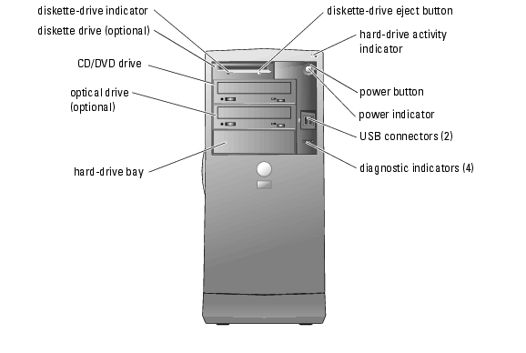
Table 1-1. Front-Panel Buttons and Indicators
|
Button/Indicator
|
Description
|
|---|
Power button | Turns system power off and on. If you turn off the system using the power button, the system can perform an orderly shutdown before power is turned off. If the power button is pressed for more than 4 seconds, the system power will turn off regardless of the current operating system state. |
Power indicator | Off indicates the system is off. Solid green indicates that the system is in a normal operating state. Amber blinking indicates that the system is powering up. Solid amber indicates that the power supply is good. To exit from a power-saving state, briefly press the power button or click or move the mouse. For more information, see your Installation and Troubleshooting Guide. |
Hard-drive activity indicator | Green blinking indicates data is being read from or written to the internal hard drives that are connected to the hard-drive controller. |
Diskette drive indicator | Green light indicates disk-drive activity. |
Diagnostic indicators (4) | Aids in diagnosing and troubleshooting the system. For more information, see your Installation and Troubleshooting Guide. |
Back-Panel Features
Figure 1-2 shows the back-panel features of the system. Figure 1-3 and Table 1-2 provide information about NIC indicators. For more information about back-panel indicators, see your Installation and Troubleshooting Guide.
Figure 1-2. Back-Panel Features
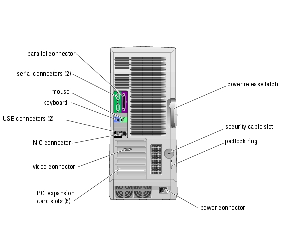
Figure 1-3. NIC Indicators

Table 1-2. NIC Indicators
|
Indicator
|
Normal Operation
|
Error Condition
|
|---|
Link | Green indicates that a 10-Mbps network connection exists. Orange indicates that a 100-Mbps network connection exists. Yellow indicates that a 1-Gbps (or 1000 Mbps) network connection exists. | Off indicates that the NIC is not detecting a physical connection to the network. |
Activity | Flashing or steady yellow indicates that the NIC is transmitting or receiving network data. | When off at the same time that the link indicator is off, the NIC is not connected to the network. |
NOTE: If the NIC is disabled in System Setup, both the link and activity indicators will be "off" regardless of
whether an active network connection is present.
|
System Features
Your system offers the following features:
- One or two Intel® Xeon™ processor(s) with a minimum clock speed of at least 2.8 GHz, and front-side bus speed of at least 800 MHz and at least 1 MB of internal cache
- A minimum of 256 MB of 400-MHz DDR II SDRAM memory, upgradable to a maximum of 12 GB by installing 256-MB, 512-MB, 1-GB, or 2-GB registered ECC memory modules in the six memory module sockets on the system board
- Support for the following internal hard-drive (non-hot-plug) configurations:
- Up to two internal 1-inch SATA hard drives with an integrated SATA controller
- Up to four internal 1-inch SATA hard drives with a SATA controller card
or
- Up to four internal 1-inch SCSI hard drives with a SCSI controller card
- One 3.5-inch peripheral drive bay for the optional diskette drive, and two 5.25-inch bays for the following supported drives: CD, DVD, combination CD-RW/DVD, DVD-RW (data only), or tape backup device
- An optional SCSI controller card that supports up to four SCSI drives
- Support for hardware RAID levels 0, 1, 5, and 10 using an optional SATA or SCSI RAID controller card
- Support for software RAID levels 0 and 1
- Support for USB 2.0
- Chassis intrusion alert
The system board includes the following built-in features:
- Dual-channel IDE controller that supports up to two supported devices including IDE CD, DVD, CD-RW/DVD combination drive, or DVD-RW, and an IDE tape backup device.
 |
NOTE: DVD devices are data only.
|
- SATA controller that supports up to two cabled SATA hard drives
- Three 64-bit, 100-MHz PCI-X expansion slots, two 2.5-GHz PCI Express expansion slots, and one 32-bit, 33-MHz PCI expansion slot
- ATI RAGE XL PCI video card with 8 MB of SDRAM video memory (nonupgradable), and a maximum resolution of 1600 x 1280 pixels and 16.7 million colors (noninterlaced)
- An integrated Gigabit Ethernet NIC, capable of supporting 1000-Mbps, 100-Mbps, or 10-Mbps data rates, with support for PXE and Wake-on-LAN
The following software is included with your system:
- The System Setup program for quickly viewing and changing the system configuration information for your system. For more information on this program, see "Using the System Setup Program."
- Enhanced security features, including a system password and a setup password, available through the System Setup program.
- Diagnostics for evaluating your system's components and devices. For information on using the system diagnostics, see "Running the System Diagnostics" in your Installation and Troubleshooting Guide.
For more information about specific features, see "Technical Specifications." For a list of documents that provide more information on your system's features, see "Other Documents You May Need."
Supported Operating Systems
Your system supports the following operating systems:
- Microsoft® Windows® Server 2003, Standard Edition
- Windows Small Business Server 2003
- Red Hat® Enterprise Linux ES (Version 3)
Power Protection Devices
Certain devices protect your system from the effects of problems such as power surges and power failures.
- PDU — Uses circuit breakers to ensure that the AC current load does not exceed the PDU's rating.
- Surge protector — Prevents voltage spikes, such as those that may occur during an electrical storm, from entering the system through the electrical outlet. They do not protect against brownouts, which occur when the voltage drops more than 20 percent below the normal AC line voltage level.
- Line conditioner — Maintains a system's AC power source voltage at a moderately constant level and provides protection from brownouts, but does not protect against a complete power loss.
- UPS — Uses battery power to keep the system running when AC power is unavailable. The battery is charged by AC power while it is available so that after AC power is lost, the battery can provide power to the system for a limited amount of time—from 5 minutes to approximately an hour. A UPS that provides only 5 minutes of battery power allows you to save your files and to shut down the system. Use surge protectors and PDUs with all universal power supplies, and ensure that the UPS is UL-safety approved.
Other Documents You May Need

|
The System Information Guide provides important safety and regulatory information. Warranty information may be included within this document or as a separate document. |
- The Getting Started Guide provides an overview of initially setting up your system.
- The Installation and Troubleshooting Guide describes how to troubleshoot the system and install or replace system components.
- Operating system documentation describes how to install (if necessary), configure, and use the operating system software.
- Documentation for any components you purchased separately provides information to configure and install these options.
- Updates are sometimes included with the system to describe changes to the system, software, and/or documentation.
|
NOTE: Always read the updates first because they often supersede information in other
documents.
|
- Release notes or readme files may be included to provide last-minute updates to the system or documentation or advanced technical reference material intended for experienced users or technicians.
Obtaining Technical Assistance
If you do not understand a procedure in this guide or if the system does not perform as expected, see your Installation and Troubleshooting Guide.
Dell Enterprise Training and Certification is available; see www.dell.com/training for more information. This service may not be offered in all locations.
Back to Contents Page