Back to Contents Page
Dell™ PowerEdge™ 1500SC Systems
Installation and
Troubleshooting Guide
 Safety First—For You and Your System
External Connections
Checking Specific System Problems
Start-Up Routine
System Orientation
Removing and Replacing the Front Bezel
Removing and Replacing the System Covers
Checking the Equipment
Inside the System
Responding to a System Management Alert Message
Troubleshooting a Wet System
Troubleshooting a Damaged System
Troubleshooting the System Battery
Troubleshooting Power Supplies
Troubleshooting Expansion Cards
Troubleshooting System Memory
Troubleshooting the Video Subsystem
Troubleshooting the System Board
Troubleshooting the Diskette Drive
Troubleshooting a CD Drive
Troubleshooting an Internal SCSI Tape Drive
Troubleshooting Hard Drives
Troubleshooting a RAID Controller Card
If your system is not working as expected, begin troubleshooting using the procedures in this section. This section guides you through some initial checks and procedures that can solve basic system problems and provides troubleshooting procedures for components inside the system. Before you start any of the procedures in this section, take the following steps:
- Get the key to the system keylock.
- Remove the front bezel.
- Lay the system on its left-side.
- Read the "Safety Instructions" in your System Information document.
- Read "Running System Diagnostics" for information about running diagnostics.
The procedures in this guide require that you remove the cover and work inside the system. While working inside the system, do not attempt to service the system except as explained in this guide and elsewhere in your system documentation. Always follow the instructions closely. Review all of the procedures in the safety instructions in your System Information document.
Observe the following precautions when working inside your system.
 |
WARNING: The power supplies in this system produce high voltages and energy
hazards, which can cause bodily harm. Only trained service technicians are
authorized to remove the system cover and access any of the components inside
the system.
|

|
CAUTION: See "Protecting Against Electrostatic Discharge" in the safety
instructions in your System Information document before performing any
procedure which requires you to open the cover.
|
Improperly set switches, controls, and loose or improperly connected cables are the most likely source of problems for the system, monitor, or other peripherals (such as a printer, keyboard, mouse, or other external equipment). A quick check of all the switches, controls, and cable connections can easily solve these problems. See Figure 2-3 for the back-panel features and connectors.
- Turn off the system, including any attached peripherals. Disconnect all the power
cables from their electrical outlets.
- If the system is connected to a PDU, turn the PDU off and then on again.
If it is not receiving power, plug it into another electrical outlet. If it still is not receiving power, try another PDU.
- Reconnect the system to the electrical outlet or PDU.
- Is the monitor working properly?
See "Troubleshooting the Video Subsystem."
- Is the keyboard working properly?
See "Troubleshooting the Keyboard."
- Are the mouse and printer working properly?
See "Troubleshooting the Basic I/O Functions."
Looking at and listening to the system is important in determining the source of a problem. Look and listen during the system's start-up routine for the indication described in Table 5-1.
Figure 5-1 shows the system orientation. The illustrations in this document are based on the system laying on its left-side.
Figure 5-1. System Orientation
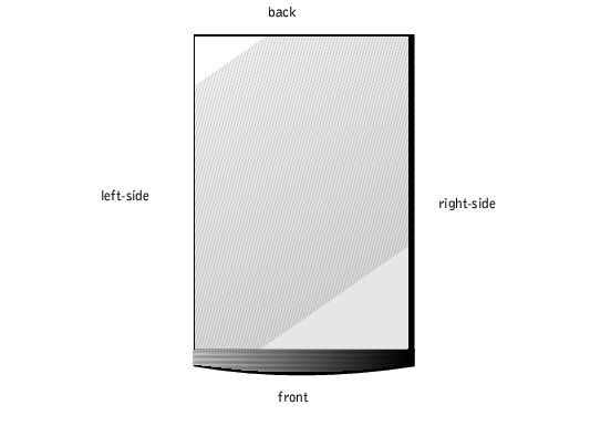
The front bezel has status and attention indicators. Removing the front bezel provides access to the hard drive(s). You must remove the front bezel and remove the system's right-side cover to gain access to internal components.
- Using the system key, unlock the front bezel.
- Grasp the bezel by the indentations on each side and pull it slightly away from the
chassis to release the two detents on the back of the bezel (see Figure 5-2).
Figure 5-2. Removing the Front Bezel
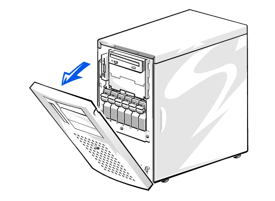
- Pivot the bezel downward until it is at right angles to the chassis.
- Grasp the bezel along the edge adjacent to the chassis and unsnap the bezel to remove
it from the chassis.
- Snap the two tabs near the lower inside edge of the bezel into the corresponding metal
clips on the chassis, and pivot the bezel upwards into its closed position until the bezel
snaps into place.
- Using the system key, lock the bezel.
The system is enclosed by a front bezel, left and right-side covers, and a top cover. Removal of the right-side cover allows access to the system board, SCSI backplane board, memory, microprocessors, and expansion cards. Removal of the left-side cover allows access to the diskette drive interface cable, and removal of the top cover allows access to the external drive bay devices interface cables. To upgrade or troubleshoot the system, remove the appropriate cover to gain access.
- Remove the front bezel (see "Removing the Front Bezel").
- Observe the precautions in "Safety First—For You and Your System."
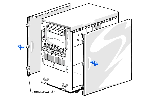
- Loosen the three thumbscrews on the front of the system (see Figure 5-3).
- Slide the system cover forward and grasp the cover at both ends.
- Carefully lift the cover away from the system.
Figure 5-3. Removing the Side Covers
- Check that no tools or parts are left inside the system.
- Fit the cover over the sides of the chassis, and slide the cover backward.
- Secure the cover with the three thumbscrews.
- Replace the front bezel.
- Remove both side covers (see "Removing the Side Covers").
- Using a #2 Phillips screwdriver, remove the two screws securing the top cover to the
chassis (see Figure 5-4).
Figure 5-4. Removing the Top Cover
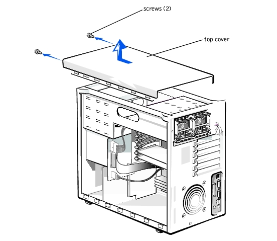
- Slide the top cover forward and grasp the cover at both ends.
- Carefully lift the cover away from the system.
- Fit the cover over the sides of the chassis, and slide the cover backward.
- Using a #2 Phillips screwdriver, secure the cover with the two screws.
- Replace both side covers (see "Replacing the Side Cover").
- Replace the front bezel.
This section provides troubleshooting procedures for equipment that connects directly to the I/O (back) panel of the system, such as the monitor, keyboard, or mouse. Before you perform any of the procedures, see "External Connections."
- Monitor
- Monitor interface cable
- Video memory
- Video logic
- Check the system and power connections to the monitor.
- Run the video tests in system diagnostics.
If the tests run successfully, the problem is not related to video hardware. Go to "Finding Software Solutions."
If the tests did not run successfully see "Getting Help" for instructions on obtaining technical assistance.
- A system error message indicates a keyboard problem
- Look at the keyboard and the keyboard cable for any signs of damage.
- Press and release each key on the keyboard.
If the keyboard and its cable appear to be free of physical damage, and the keys work, go to step 4.
If the keyboard or its cable are damaged, continue to step 3.
- Swap the faulty keyboard with a working keyboard.
If the problem is resolved, the keyboard must be replaced. See "Getting Help," for instructions on obtaining technical assistance.
- Run the keyboard test in system diagnostics.
If you can use the keyboard to select the keyboard test, go to step 6.
If you cannot use the keyboard to select the keyboard test, continue to step 5.
- Swap the faulty keyboard with a working keyboard.
- Did the keyboard test run successfully?
If the problem is resolved, the keyboard must be replaced. If the problem is not resolved, the keyboard controller on the system board is faulty. See "Getting Help," for instructions on obtaining technical assistance.
- A system error message indicates an I/O port problem
- A device connected to the port does not function properly
- Enter the System Setup program, and check the Serial Port 1 and Parallel Port
settings.
If the communications ports are set to Enabled, go to step 3.
If the communications ports are not set to Enabled, continue to step 2.
- Change the Serial Port 1, and Parallel Port settings to Enabled; then reboot the
system.
- Check the system setup. See "Using the System Setup Program" in the User's Guide
for instructions.
If the system setup is correct, go to step 5.
- Change the necessary statements in the system setup. If the port problem is confined
to a particular application program, see the application program's documentation for
specific port configuration requirements.
- Reboot the system from the diagnostics diskette, and run the serial ports test and/or
the parallel ports test in system diagnostics.
If the tests did not run successfully, see "Getting Help," for instructions on obtaining technical assistance.
- If the problem persists, see one of the following procedures, "Troubleshooting a
Parallel Printer" or "Troubleshooting a Serial I/O Device," depending on the
malfunctioning device.
- Device connected to the serial port is not working
- Turn off the system and any peripheral devices connected to the serial port.
- Swap the interface cable with a known working cable.
If the problem is resolved, the interface cable must be replaced. See "Getting Help," for instructions on obtaining technical assistance.
- Turn off the system and the serial device, and swap the device with a comparable
device.
- Turn on the power to the system and the serial device.
If the problem is resolved, the serial device must be replaced. If the problem is not resolved, see "Getting Help," for instructions on obtaining technical assistance.
- Parallel printer is not working
- Turn off the power from the printer and the system.
- Swap the parallel printer interface cable with a known working cable.
- Turn on the power to the printer and the system.
- Attempt a print operation.
If the print operation is successful, the interface cable must be replaced. See "Getting Help," for instructions on obtaining technical assistance.
- Run the printer's self-test.
If the self-test is not successful, the printer is probably defective. See "Getting Help," for instructions on obtaining technical assistance.
- A system error message indicates a problem
- Device connected to the port is not working
- Enter the System Setup program, and check that the USB ports are enabled. See
"Using the System Setup Program" in the User's Guide for instructions.
- Turn off the system and any USB devices.
If there is only one USB device connected to the system, go to step 5.
- Disconnect the USB devices, and connect the malfunctioning device to the other port.
- Apply power to the system and the reconnected device.
If the problem is resolved, the USB port might be defective. See "Getting Help," for instructions on obtaining technical assistance.
- If possible, swap the interface cable with a known working cable.
If the problem is resolved, the interface cable must be replaced. See "Getting Help," for instructions on obtaining technical assistance.
- Turn off the system and the USB device, and swap the device with a comparable
device.
- Turn on the power to the system and the USB device.
If the problem is resolved, the USB device must be replaced. If the problem is not resolved, see "Getting Help," for instructions on obtaining technical assistance.
- NIC cannot communicate with network
- Enter the System Setup program and confirm that the NIC is enabled.
See "Using the System Setup Program" in the User's Guide for instructions.
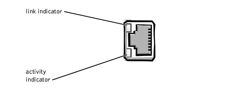
- Check the two indicators on the left and right corners of the NIC connector on the
system's back-panel (see Figure 5-5).
The green link indicator shows that the adapter is connected to a valid link partner. The amber activity indicator lights if network data is being sent or received.
- If the link indicator is not on, check all cable connections.
- Try changing the auto negotiation setting, if possible.
- Try another port on the switch or hub.
- If the activity indicator does not light, the network driver files might be damaged or
deleted.
- Reinstall the drivers.
- Ensure the appropriate drivers are installed and the protocols are bound.
Figure 5-5. NIC Indicators
In Figure 5-6, the system cover and front bezel are removed to provide an interior view of the system.
Figure 5-6. Inside the System

The system board can accommodate up to six PCI expansion cards (four cards at 64-bit/66 MHz and two cards at 32-bit/33 MHz). The system memory is contained in four memory module slots that must be populated with at least two memory modules. The peripheral bay provides space for a 3.5-inch diskette drive and a CD drive and one other device.
The hard drive bays provide space for up to six 1-inch SCSI hard drives. These hard drives are connected to a SCSI host adapter on the system board or on an expansion card, via the SCSI backplane board.
In a single nonredundant power supply system, the power supply will connect directly to and provide power to the system board, SCSI backplane, and internal peripherals. In a redundant hot-pluggable power-supply system, the dual hot-pluggable power supplies connect directly to the power-supply distribution board (PSDB) which then provides power to the system board, SCSI backplane, and internal peripherals.
For non-SCSI drives such as the diskette drive and CD drive, an interface cable connects the devices to the system board. For SCSI devices, interface cables connect externally accessible SCSI devices and the SCSI backplane board to a SCSI host adapter either on the system board or on an expansion card. (For more information, see "Installing Drives.")
During an installation or troubleshooting procedure, you may be required to change a jumper. For information on the system board jumpers, see "Jumpers and Connectors."
The optional system management applications monitor critical system voltages and temperatures, the system cooling fans, and the status of the SCSI hard drives in the system. Alert messages appear in the alert log window. For information about the alert log window and options, see your system management software documentation.
- Liquid spills
- Splashes
- Excessive humidity
- Turn off the system, including any attached peripherals, and disconnect the system
from the electrical outlet.
- Remove the system covers (see "Removing the Side Covers").
- Remove all expansion cards installed in the system.
See "Removing an Expansion Card" in "Installing System Board Options."
- Let the system dry thoroughly for at least 24 hours.
- Replace the system covers, reconnect the system to the electrical outlet, and turn on
the system.
If the system does not start up properly, see "Getting Help," for instructions on obtaining technical assistance.
- If the system starts up normally, shut down the system and reinstall all expansion cards
you removed in step 3.
See "Installing an Expansion Card" in "Installing System Board Options."
- Run the system board tests in system diagnostics to confirm that the system is working
properly.
If the tests did not complete successfully, see "Getting Help," for instructions on obtaining technical assistance.
- System dropped or damaged
- Check the following connections:
- Expansion-card connections to the system board
- Drive carrier connections to the SCSI backplane board
- Ensure that all cables are properly connected and that all components are properly
seated in their connectors and sockets.
- Run the system board tests in system diagnostics.
If the tests did not complete successfully, see "Getting Help," for instructions on obtaining technical assistance.
- Error message shows problem with the battery
- System setup program loses the system configuration information
- System date and time will not stay current
The system battery maintains system configuration, date, and time information in a special section of memory when you turn off the system. The operating life of the battery ranges from 2 to 5 years, depending on how you use the system (for example, if you keep the system on most of the time, the battery gets little use and lasts longer).
You can operate the system without a battery; however, the system configuration information maintained by the battery in NVRAM is erased each time you shut down the system. Therefore, you must reenter the system configuration information and reset the options each time the system boots until you replace the battery.
- Reenter the time and date through the System Setup program.
- Turn off and disconnect the system from the electrical outlet for a few hours.
- Reconnect the system to the electrical outlet and turn the system on again.
- Enter the System Setup program.
If the date and time are not correct in the System Setup program, replace the battery (see "Replacing the System Battery").
If the problem is not resolved by replacing the battery, see "Getting Help," for instructions on obtaining technical assistance.
 |
NOTE: Some software might cause the system time to speed up or slow down. If the system
seems to operate normally except for the time kept in the System Setup program, the problem
might be caused by software rather than by a defective battery.
|
|
NOTE: If the system is turned off for long periods of time (for weeks or months), the NVRAM
might lose its system configuration information. This situation is not caused by a defective
battery.
|
- Amber fault indicator on the system front panel lights up (redundant only)
- Red fault indicator blinks on the power supply or lights up continuously (redundant
only)
- No power
- Turn off the system, including any attached peripherals, and disconnect the system
from the electrical outlet.
- For nonredundant system's, remove the system's right-side cover and check that the
power connectors are properly connected or if they are loose.
For redundant system's, check that the power supplies are properly installed.
- Slide the new power supply into the chassis.
- If you removed the system cover, replace the system cover and connect the system to
its electrical outlet.
- Turn on the system including any attached peripherals.
If the problem persists, see "Getting Help," for information on obtaining technical assistance.
- Error message indicates an expansion-card problem
- Expansion card seems to perform incorrectly or not at all
- Turn off the system, including any attached peripherals, and disconnect the system
from the electrical outlet.
- Remove the right-side cover (see "Removing the Side Covers").
- Remove the PCI fan shroud (see "Removing the PCI Cooling Shroud" in "Installing
System Board Options").
- Verify that each expansion card is firmly seated in its connector.
- Verify that any appropriate cables are firmly connected to their corresponding
connectors on the expansion cards.
- Replace the PCI fan shroud (see "Installing the PCI Cooling Shroud" in "Installing
System Board Options").
- Replace the right-side cover (see "Replacing the Side Cover").
- Turn on the system including any attached peripherals.
- Run the Quick Tests in system diagnostics. If the problem still exists, go to step 10.
- Turn off the system, including any attached peripherals, and disconnect the system
from the electrical outlet.
- Remove the right-side cover (see "Removing the Side Covers").
- Remove all expansion cards installed in the system (see "Removing an Expansion
Card" in "Installing System Board Options").
- Replace the right-side cover (see "Replacing the Side Cover").
- Turn on the system including any attached peripherals.
- Run the Quick Tests in system diagnostics.
If the tests do not complete successfully, see "Getting Help," for information on obtaining technical assistance.
- Turn off the system, including any attached peripherals, and disconnect the system
from the electrical outlet.
- Remove the right-side cover (see "Removing the Side Covers").
- Reinstall one of the expansion cards you removed in step 12 (see "Installing an
Expansion Card" in "Installing System Board Options").
- Repeat steps 13 through 18 for each of the remaining expansion cards.
If you have reinstalled all of the expansion cards and the Quick Tests are still failing, see "Getting Help," for information on obtaining technical assistance.
- Faulty memory module
- Faulty system board
- Turn on the power to the system, including any attached peripherals.
If there are no error messages, go to step 17.
- Enter the System Setup program to check the system memory setting.
See "Using the System Setup Program," in the User's Guide for instructions.
- If the amount of memory does match the system memory setting, go to step 17.
- Turn off the system, including any attached peripherals, and disconnect the system
from its electrical outlet.
|
|
CAUTION: See "Protecting Against Electrostatic Discharge" in the safety
instructions in your System Information document.
|
- Remove the system's right-side cover (see "Removing the Side Covers").
- Remove the memory module cooling shroud (see "Cooling Shrouds" in "Installing
System Board Options").
- Reseat the memory modules in their sockets.
- Install the memory modules cooling shroud (see "Cooling Shrouds" in "Installing
System Board Options").
- Replace the system's right-side cover, reconnect the system to power, and turn on the
system.
- Enter the System Setup program and check the system memory again.
If the amount of memory installed does not match the system memory setting, then perform the following steps:
- Turn off the system.
- Remove the right-side cover.
- Remove the memory modules cooling shroud.
- Go to step 12.
- Reboot the system, and observe the monitor screen and the Num Lock, Caps Lock,
and Scroll Lock indicators on the keyboard.
If the monitor screen does remain blank, and the Num Lock, Caps Lock, and Scroll Lock indicators on the keyboard remain on:
- Turn off the system.
- Remove the right-side cover.
- Remove the memory modules cooling shroud.
- Go to step 12.
If the monitor screen does not remain blank, and the Num Lock, Caps Lock, and Scroll Lock indicators on the keyboard remain on, continue to step 18.
|
NOTE: There are multiple configurations for the memory modules; see "Memory Module
Installation Guidelines" in "Installing System Board Options." The following steps are an
example of one configuration.
|
- Swap the memory module pair in PAIR 1 with a pair of the same capacity.
- Install the memory modules cooling shroud (see "Cooling Shrouds" in "Installing
System Board Options").
- Replace the system's right-side cover and reconnect the system to an electrical outlet.
- Reboot the system, and observe the monitor screen and the indicators on the
keyboard.
- If the problem still exists:
- Turn off the system.
- Remove the right-side cover.
- Remove the memory modules cooling shroud.
- Repeat steps 12 through 15 for the pair of memory modules installed in PAIR2.
If the problem is not resolved, see "Getting Help," for instructions on obtaining technical assistance.
- Run the system memory test in system diagnostics.
If the test does not complete successfully, see "Getting Help," for instructions on obtaining technical assistance.
- Monitor not operating
- Monitor interface cable not connected correctly or is faulty
- Video logic problems
- Check the system and power connections to the monitor.
- Run the video tests in system diagnostics.
If the tests run successfully, the problem is not related to video hardware. See "Finding Software Solutions."
If the tests did not run successfully see "Getting Help," for instructions on obtaining technical assistance.
- Error message indicating a system board problem
- Turn off the system, including any attached peripherals, and disconnect the system
from the electrical outlet.
- Remove the right-side cover (see "Removing the Side Covers").
- Remove all expansion cards except the SCSI host adapter card for the boot drive (see
"Removing an Expansion Card" in "Installing System Board Options").
- Replace the right-side cover (see "Replacing the Side Cover").
- Turn on the system including any attached peripherals.
- Run the Quick Tests in system diagnostics.
If the tests does not run successfully, see "Getting Help," for instructions on obtaining technical assistance.
- Turn off the system, including any attached peripherals, and disconnect the system
from the electrical outlet.
- Remove the right-side cover (see "Removing the Side Covers").
- Reinstall one of the expansion cards that you removed in step 3 (see "Installing an
Expansion Card" in "Installing System Board Options").
- Replace the right-side cover (see "Replacing the Side Cover").
- Turn on the system including any attached peripherals.
- Run the Quick Tests again.
If the tests does not complete successfully, see "Getting Help," for instructions on obtaining technical assistance.
- Repeat steps 7 through 12 for the remaining expansion cards that you removed in
step 3.
If you have reinstalled all of the expansion cards and the problem still persists, see "Getting Help," for instructions on obtaining technical assistance.
- Error message indicating a diskette drive problem during execution of either the boot
routine or system diagnostics
- Enter the system setup program, and verify that the system is configured correctly. See
"Using the System Setup Program" in the User's Guide for instructions.
- Run the diskette drive tests in system diagnostics to see whether the diskette drive now
works correctly.
- Turn off the system, including any attached peripherals, and disconnect the system
from its electrical outlet.
- Remove the system covers (see "Removing and Replacing the System Covers").
- Remove the cooling shrouds (see "Cooling Shrouds" in "Installing System Board
Options").
- Verify that the diskette drive's interface cable is securely connected between the
diskette drive and the system board.
- Replace the cooling shrouds (see "Cooling Shrouds").
- Reinstall the system covers (see "Removing and Replacing the System Covers").
- Connect the system to its electrical outlet and turn on the system, including any
attached peripherals.
- Run the diskette drive tests in system diagnostics to determine whether the diskette
drive works correctly.
- If the drive still does not work, remove all expansion cards (see "Removing an
Expansion Card" in "Installing System Board Options").
- Run the diskette drive tests in system diagnostics to determine whether the diskette
drive now works correctly.
If the test ran successfully, an expansion card might be conflicting with the diskette drive logic, or you may have a faulty expansion card. Continue to step 13.
If the test failed, see "Getting Help," for instructions on obtaining technical assistance.
- Reinstall one of the expansion cards you removed in step 11 (see "Installing an
Expansion Card" in "Installing System Board Options").
- Retest and run the diskette drives test in system diagnostics to determine whether the
diskette drive subsystem now works correctly.
- Repeat steps 13 and 14 until all expansion cards have been reinstalled or until one of
the expansion cards prevents the system from booting from the diagnostics diskette.
If the problem is not resolved, see "Getting Help," for instructions on obtaining technical assistance.
- System cannot read data from the CD
- CD indicator fails to flash during boot
- Turn off the system, including any attached peripherals, and disconnect the system
from its electrical outlet.
- Remove the system's right-side cover (see "Removing the Side Covers").
- Remove the cooling shrouds (see "Cooling Shrouds" in "Installing System Board
Options").
- Verify that the CD drive interface cable is securely connected between the CD drive
and the system board.
- Connect the system to its electrical outlet and turn on the system, including any
attached peripherals.
- Run the IDE devices tests in system diagnostics to determine whether the CD drive
now works correctly.
If the problem is not resolved, see "Getting Help," for instructions on obtaining technical assistance.
- Defective tape drive
- Defective tape cartridge
- Software or device driver
- Remove the tape that was in use when the problem occurred and replace it with a tape
that you know is not defective.
- Verify that any required SCSI device drivers are installed on the hard drive and are
configured correctly.
- See "Using the Dell OpenManage Server Assistant CD" in the User's Guide for
instructions on installing and configuring device drivers for the system's integrated
SCSI host adapter or an optional host adapter card.
- For any other type of SCSI host adapter card, see the documentation that
accompanied the SCSI host adapter card.
- Reinstall the tape backup software as instructed in the tape-backup software
documentation.
- Remove the cooling shrouds (see "Cooling Shrouds" in "Installing System Board
Options").
- Replace the SCSI cable that connects the tape drive to the SCSI host adapter or
system board.
- Replace the cooling shrouds (see "Cooling Shrouds" in "Installing System Board
Options").
- Reconnect the system to the electrical outlet and apply power.
- If the problem is not resolved, replace the tape drive. If the problem persists, see
"Getting Help," for instructions on obtaining technical assistance.
- The drive itself
- SCSI backplane board
- SCSI cable connections to the system board
- Systems using an optional host adapter card issue the following signals by using the
drive indicator lights adjacent to each hard drive:
- Hard drive failure indicator on the control panel lights.
- If a drive shows signs of imminent failure, the drive online indicator stays on and the drive failure indicator blinks on briefly each second.
- If a drive has failed, the drive online indicator turns off and the drive failure indicator blinks on briefly each second.
 |
NOTICE: This troubleshooting procedure can destroy data stored on the hard drive. Before you
proceed, back up all the files on the hard drive.
|
- If the integrated SCSI host adapter is being used to control the SCSI backplane board,
reboot the system and press <Ctrl><a> to enter the SCSI configuration utility
program.
|
NOTE: If your system has an optional RAID controller installed, reboot the system and
press <Ctrl><h>, <Ctrl><a>, or <Ctrl><m> depending on the utility. See the
documentation supplied with the controller for information on the configuration utility.
|
- Check that the primary SCSI channel is enabled, and reboot the system.
- Verify that the device drivers are installed and configured correctly.
See the documentation for the system's operating system.
- Remove the hard drive and install it in another drive bay.
- If the problem is resolved, reinstall the drive carrier in the original bay.
If the hard drive functions properly in the original bay, the drive carrier could have intermittent problems. Replace the hard drive (see "Installing SCSI Hard Drives" in "Installing Drives").
If the hard drive still does not function properly in the original bay, the SCSI backplane board has a defective connector. See "Getting Help," for instructions on obtaining technical assistance.
- Remove the cooling shrouds (see "Cooling Shrouds" in "Installing System Board
Options").
- Check the SCSI cable connections inside the system:
- Turn off the system, including any attached peripherals, and disconnect the
system from its electrical outlet.
- Remove the system cover.
- Check the SCSI cable connection to the SCSI host adapter.
The SCSI cable may be connected to the internal SCSI host adapter on the system board or a SCSI host adapter installed in an expansion slot.
- Partition and logically format the hard drive. If possible, restore the files to the drive.
To partition and logically format the drive, see the documentation for the system's operating system.
- If the problem is not resolved, see "Getting Help," for instructions on obtaining
technical assistance.
Your system may contain an optional RAID controller card. If you encounter problems with a controller, see the RAID controller's documentation for detailed information on troubleshooting.
Back to Contents Page