Back to Contents Page
Dell™ PowerEdge™ 1500SC Systems
Installation and
Troubleshooting Guide
 Removing the Fan
Replacing the Fan
Removing and Installing Power Supplies
Expansion Cards
Cooling Shrouds
Adding Memory
Microprocessor Upgrades
Replacing the System Battery
This section describes how to install the following options:
- Expansion cards
- Memory upgrades
- Microprocessor upgrades
This section also includes instructions for replacing the fan, cooling shrouds, power supplies, and system battery, if necessary.
Use Figure 6-1 to locate the system board features. Table 6-1 describes the system board connectors and sockets.
 |
WARNING: Before you perform this procedure, you must turn off the system and
disconnect it from its power source. For more information, see "Safety First—
For You and Your System" in "Troubleshooting Your System."
|
Figure 6-1. System Board Connectors and Sockets
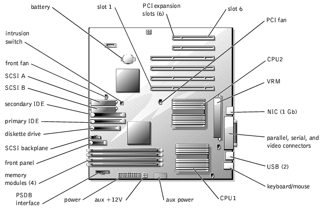
Table 6-1. System Board Connectors and Sockets
|
Connector or Socket
|
Description
|
|---|
SCSI BACKPLANE | Hot-pluggable SCSI backplane board interface cable connector |
BATTERY | System battery connector |
PARALLEL, COMn, VGA | Parallel port connector; sometimes referred to as LPT1, serial port connectors; sometimes referred to as COM1, video connector |
DIMM_n | Memory riser card connectors (2) |
ENET_1GB | Ethernet connector |
FAN | Power for the front system fan |
SCSI_n | Power and data to the diskette and CD drive from the system board |
PRIMARY IDE | CD drive connector |
SECONDARY IDE | Tape drive connector |
DISKETTE | Diskette connector |
KYBD | Keyboard connector |
MOUSE | Mouse connector |
PSDB I/F | Power supply distribution board interface connector |
CNTL PNL | System control panel connector |
POWERn | Power connector |
PCI FAN | Power connector for the PCI fan |
CPU__n | Microprocessor sockets |
VRM_n | Voltage regulator module connector |
SLOT_n | Expansion card connectors (SLOT_1—SLOT_6) |
INTRUSION SW | Intrusion switch connector |
USBn | USB connector |
NOTE: For the full name of an abbreviation or acronym used in this table, see
"Abbreviations and Acronyms ."
|
- Turn off the system, including any attached peripherals, and disconnect the system
from the electrical outlet.
- Remove the system's right-side cover (see "Removing the Side Covers" in
"Troubleshooting Your System").
- Remove the cooling shrouds (see "Cooling Shrouds").
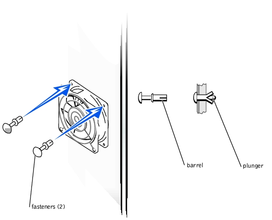
- Remove the two fasteners that secure the fan to the chassis (see Figure 6-2).
- On the opposite side of the chassis from the fan, push the plunger of each fastener
back into the fastener barrel, using the flat surface of a flat-tipped screwdriver, or
other small flat object.
- On the fan side, grasp the extended head of the fastener and pull the fastener
completely out of the chassis wall.
Figure 6-2. Removing the Fan
- Disconnect the fan power cable from the fan connector on the system board (see
Figure 6-1).
- Carefully pull the fan power cable through the hole in the chassis wall and lift the fan
out of the chassis.
- Route the fan power cable through the hole in the chassis wall.
- Connect the fan power cable to the fan connector on the system board (see
Figure 6-1).
- Place the fan in the hinge bracket and then swing it backward.
- Secure the fan to the chassis using the two fasteners you removed in step 3 of
"Removing the Fan."
- Replace the cooling shrouds (see "Cooling Shrouds").
- Replace the system's right-side cover.
Your system might have the single nonredundant power supply or the hot-pluggable dual power supplies.
- Remove the front bezel (see "Removing the Front Bezel" in "Troubleshooting Your
System").
- Remove the system covers (see "Removing and Replacing the System Covers" in
"Troubleshooting Your System").
- Remove the cooling shrouds (see "Cooling Shrouds").
- Disconnect the power cable harness from the SCSI backplane, system board, diskette
drive, and any other devices in the peripheral drive bay.
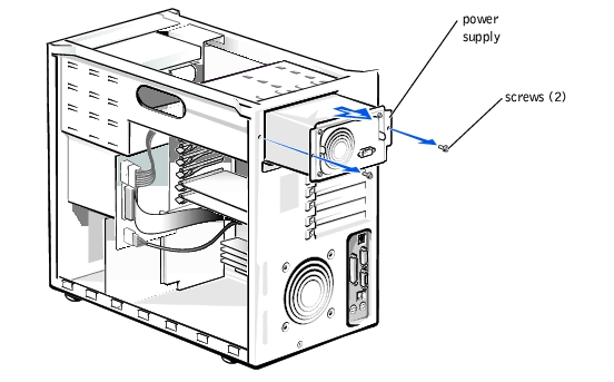
- Using a #2 Phillips screwdriver, remove the two screws securing the power supply to
the chassis (see Figure 6-3).
- Slide the power supply out of the chassis.
Figure 6-3. Removing and Installing the Nonredundant Power Supply
- Slide the new power supply into the chassis.
- Reconnect the power cable harness to the SCSI backplane, system board, diskette
drive, and any other devices in the peripheral drive bay.
- Replace the cooling shrouds (see "Cooling Shrouds").
- Secure the power supply to the chassis using the two screws you removed in step 5.
- Remove the power supply by squeezing the power supply handle, and pulling the
power supply straight out to clear the chassis (see Figure 6-4).
Figure 6-4. Removing and Installing the Redundant Power Supplies
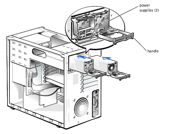
- Install the power supply by sliding the new power supply into the chassis and swinging
the handle closed until it snaps into place.
There are six expansion card slots available. Expansion card slots 1 and 2 reside on the secondary 64-bit/66 MHz bus, card slots 3 and 4, reside on the primary 64-bit/66 MHz bus, and card slots 5 an 6 reside on the 32-bit/33 MHz bus.
- Turn off the system, including any attached peripherals, and disconnect the system
from the electrical outlet.
- Remove the right-side cover (see "Removing the Side Covers" in "Troubleshooting
Your System").
- Remove the PCI cooling shroud (see "Removing the PCI Cooling Shroud").
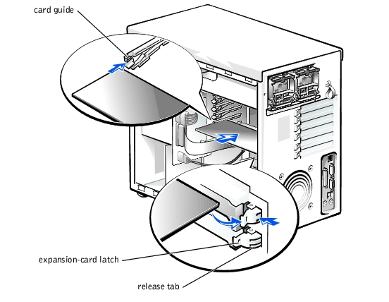
- Open the plastic expansion-card latch and remove the expansion-card filler bracket
(see Figure 6-5).
- Press and hold the plastic tab on the back of the chassis.
- Press the release tab on the latch inside the chassis.
- Open the expansion-card latch and remove the filler bracket.
- Ensure that the card guide latch is open if the expansion-card is a full-length card.
- Install the new expansion card (see Figure 6-5).
- Position the expansion-card so that the board-edge connector aligns with the
expansion-card connector on the system board.
- Insert the card-edge connector firmly into the expansion-card connector until the
card is fully seated.
- Close the expansion-card latch.
- Close the card guide latch if the new expansion card is a full-length card.
Figure 6-5. Installing an Expansion Card
- Connect any cables that should be attached to the card.
See the documentation that came with the card for information about its cable connections.
- Replace the PCI cooling shroud (see "Installing the PCI Cooling Shroud").
- Replace the right-side cover (see "Removing the Side Covers" in "Troubleshooting
Your System").
- Turn off the system, including any attached peripherals, and disconnect the system
from the electrical outlet.
- Remove the right-side cover (see "Removing the Side Covers" in "Troubleshooting
Your System").
- Replace the PCI cooling shroud (see "Removing the PCI Cooling Shroud").
- Disconnect any cables connected to the card.
- To release the expansion card latch, press and hold the clip on the back of the chassis
while you press the release tab on the latch inside the chassis, and then rotate the latch
to the open position (see Figure 6-5).
- Grasp the expansion card by its top corners, and carefully remove it from the
expansion-card connector.
- If you are removing the card permanently, install a metal filler bracket over the empty
card-slot opening.
 |
NOTE: Installing a filler bracket over an empty expansion card slot is necessary to
maintain Federal Communications Commission (FCC) certification of the system. The
brackets also keep dust and dirt out of the system and aid in proper cooling and airflow
inside the system.
|
- Replace the PCI cooling shroud (see "Installing the PCI Cooling Shroud").
- Replace the right-side cover (see "Removing the Side Covers" in "Troubleshooting
Your System").
Your system contains two cooling shrouds. The PCI cooling shroud covers the expansion cards and the microprocessor/memory module cooling shroud covers the microprocessors and memory modules. This shroud is hinged in the middle to facilitate the removal and installation of the shroud.
- Turn off the system, including any attached peripherals, and disconnect the system
from the electrical outlet.
- Remove the system's right-side cover (see "Removing the Side Covers" in
"Troubleshooting Your System").
- Use your index finger to pull the back-panel release tab and swing the cooling shroud
up and out of the chassis (see Figure 6-6).
- Disconnect the PCI fan power cable from the system board (see Figure 6-1).
Figure 6-6. Removing and Installing the PCI Cooling Shroud
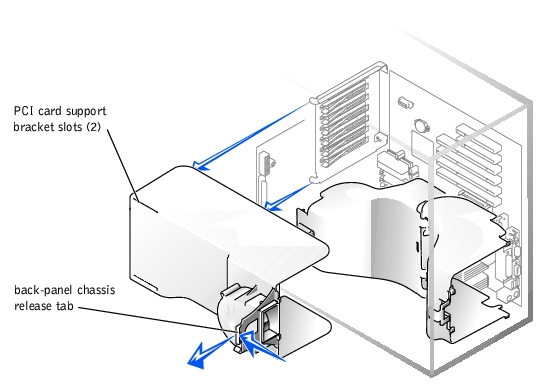
- Connect the PCI fan power cable to the system board.
- Lower the cooling shroud into the chassis ensuring that the shroud is aligned with the
tabs on the PCI card support bracket (see Figure 6-6).
- Swing the cooling shroud down until it snaps into place securing the shroud to the
system (see Figure 6-6).
- Replace the system's right-side cover.
- Replace the front bezel.
- Turn off the system, including any attached peripherals, and disconnect the system
from the electrical outlet.
- Remove the system's right-side cover (see "Removing the Side Covers" in
"Troubleshooting Your System").
- Press the release tab on the memory modules shroud and rotate the shroud until the
tabs release from the slots in the microprocessor shroud (see Figure 6-7).
- Lift the memory modules shroud from the system.
- While pulling the release tab on the shroud that covers the microprocessors, lift the
shroud upward so that the four retaining tabs that secure the shroud to the back of the
chassis can be pulled through the back panel (see Figure 6-7).
- Lift the microprocessor cooling shroud up and out of the chassis.
Figure 6-7. Removing and Installing the Microprocessor and Memory
Module Cooling Shrouds

- Lower the microprocessor cooling shroud into the chassis ensuring that the four
securing tabs of the shroud is aligned with the holes in the back-panel (see Figure 6-7).
- Press the cooling shroud down until it snaps into place securing the cooling shroud to
the back-panel (see Figure 6-7).
- Insert the two tabs on the memory module shroud into the two slots on the
microprocessor shroud and swing the memory module shroud down until it snaps into
place.
- Replace the system's right-side cover.
- Replace the front bezel.
The memory modules are contained in four memory module sockets. The system can accommodate 128 MB to 4 GB of registered memory modules. The memory module sockets are arranged in two pairs. PAIR 1 consists of DIMMA and DIMMB and PAIR 2 consists of DIMMC and DIMMD. Memory modules must be installed in pairs and must be indentical (type and vendor).
The system is upgradable to 4 GB by installing combinations of 128- 256-, 512-MB, and 1 GB registered memory modules. If you receive an error message stating that maximum memory has been exceeded, see "Indicators, Messages, and Codes," for detailed information. You can purchase memory upgrade kits from Dell as needed.
|
NOTE: The memory modules must be PC-133 compliant.
|
Starting with the socket nearest the power connector, the memory module sockets are labeled "PAIR1 DIMMA and DIMMB" and "PAIR2 DIMMC and DIMMD" (see Figure 6-8). When you install memory modules, follow these guidelines:
- You must install memory modules in indentical pairs.
- Install a pair of memory modules in sockets PAIR1 DIMMA and DIMMB before
installing the second pair in sockets PAIR2 DIMMC and DIMMD.
- When memory modules are installed in both PAIR1 and PAIR2, install memory
modules of the same size for optimum performance.
Figure 6-8. Memory Module Sockets
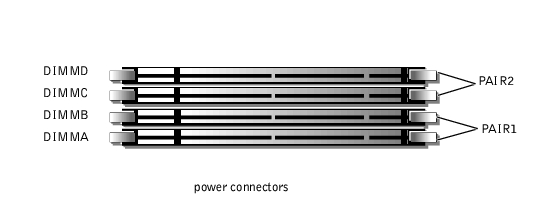
Table 6-2 illustrates several sample memory configurations based on these guidelines.
Table 6-2. Sample Memory Module Configurations
|
Total Desired
Memory
|
PAIR1
|
PAIR2
|
|---|
|
DIMMA
|
DIMMB
|
DIMMC
|
DIMMD
|
|---|
128 MB | 64 MB | 64 MB | None | None |
256 MB | 64 MB | 64 MB | 64 MB | 64 MB |
256 MB | 128 MB | 128 MB | None | None |
512 MB | 128 MB | 128 MB | 128 MB | 128 MB |
1 GB | 256 MB | 256 MB | 256 MB | 256 MB |
1 GB | 512 MB | 512 MB | None | None |
2 GB | 512 MB | 512 MB | 512 MB | 512 MB |
2 GB | 1 GB | 1 GB | None | None |
4 GB | 1 GB | 1 GB | 1 GB | 1 GB |
|
WARNING: Before you perform this procedure, you must turn off the system and
disconnect it from its power source. For more information, see "Safety First—
For You and Your System" in "Troubleshooting Your System."
|

|
CAUTION: See "Protecting Against Electrostatic Discharge" in the safety
instructions in your System Information document.
|
- Turn off the system, including any attached peripherals, and disconnect the AC power
from the electrical outlet.
- Remove the system's right-side cover (see "Removing the Side Covers" in
"Troubleshooting Your System").
- Remove the memory module cooling shroud (see "Removing the Microprocessor and
Memory Module Cooling Shrouds").
- Install or replace the memory module pairs as necessary to reach the desired memory
total (see "Installing Memory Modules" or "Removing Memory Modules").
See Figure 6-8 for the memory module socket locations.
- Reinstall the memory module cooling shroud (see "Installing the Microprocessor and
Memory Module Cooling Shrouds").
- Reinstall the system's right-side cover, reconnect the system to the electrical outlet,
and turn on system. After the system completes the POST routine, it runs a memory
test.
The system detects that the new memory does not match the system configuration information, which is stored in NVRAM. The monitor displays an error message that ends with the following words:
Press <F1> to continue; <F2> to enter System Setup
- Press <F2> to enter the System Setup program, and check the System Memory
setting in the system data box on the System Setup screens. The system should have
already changed the value in the System Memory setting to reflect the newly installed
memory.
- If the System Memory value is incorrect, one or more of the memory modules may not
be installed properly. Repeat steps 1 through 4 ensuring that the memory modules are
firmly seated in their sockets.
- Run the system memory test in system diagnostics.
- Replace the front bezel.
|
WARNING: Before you perform this procedure, you must turn off the system and
disconnect it from its power source. For more information, see "Safety First—
For You and Your System" in "Troubleshooting Your System."
|
|
|
CAUTION: See "Protecting Against Electrostatic Discharge" in the safety
instructions in your System Information document.
|
- Turn off the system, including any attached peripherals, and disconnect the AC power
from the electrical outlet.
- Remove the system's right-side cover (see "Removing the Side Covers" in
"Troubleshooting Your System").
- Remove the memory module cooling shroud (see "Removing the Microprocessor and
Memory Module Cooling Shrouds").
- Locate the memory module sockets in which you will install a memory module.
Figure 6-8 shows the order of the memory module sockets.
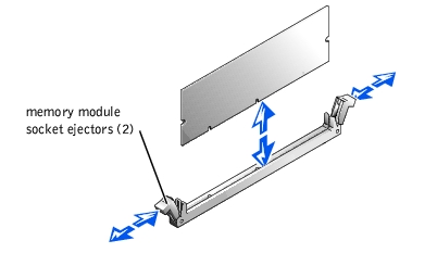
- Press down and outward on the memory module socket ejectors, as shown in
Figure 6-9, to allow the memory module to be inserted into the socket.
Figure 6-9. Installing a Memory Module

- Align the memory module's edge connector with the alignment keys, and insert the
memory module in the socket (see Figure 6-9).
The memory module socket has two alignment keys that allow the memory module to be installed in the socket in only one way.
- Press down on the memory module with your thumbs while pulling up on the ejectors
with your index fingers to lock the memory module into the socket (see Figure 6-9).
When the memory module is properly seated in the socket, the memory module socket ejectors should align with the ejectors on the other sockets with memory modules installed.
- Repeat steps 4 through 7 of this procedure to install the remaining memory modules.
- Perform steps 5 through 10 of "Performing a Memory Upgrade."
|
WARNING: Before you perform this procedure, you must turn off the system and
disconnect it from its power source. For more information, see "Safety First—
For You and Your System" in "Troubleshooting Your System."
|
|
|
CAUTION: See "Protecting Against Electrostatic Discharge" in the safety
instructions in your System Information document.
|
- Turn off the system, including any attached peripherals, and disconnect the AC power
from the electrical outlet.
- Remove the system's right-side cover (see "Removing the Side Covers" in
"Troubleshooting Your System").
- Remove the memory module cooling shroud (see "Removing the Microprocessor and
Memory Module Cooling Shrouds").
- Locate the memory module sockets in which you will remove memory modules.
Figure 6-8 shows the order of the memory module sockets.
- Press down and outward on the memory module socket ejectors until the memory
module pops out of the socket (see Figure 6-10).
Figure 6-10. Removing a Memory Module
To take advantage of future options in speed and functionality, you can add a second microprocessor or replace either the primary or secondary microprocessor.
 |
NOTICE: The second microprocessor must be of the same type and speed as the first
microprocessor.
|
Each microprocessor and its associated cache memory are contained in a PGA package that is installed in a ZIF socket on the system board. A second ZIF socket accommodates a secondary microprocessor. The secondary micro-processor must have the same operating frequency as the primary micro-processor. For example, if the system has a 1.13-GHz primary microprocessor, your secondary microprocessor must also be a 1.13-GHz microprocessor.
In a single microprocessor system, the microprocessor must be installed in the PROC_1 ZIF socket.
The following items are included in the microprocessor upgrade kit:
- A microprocessor
- A heat sink
- A securing clip
- A VRM, if adding a second microprocessor
|
|
CAUTION: See "Protecting Against Electrostatic Discharge" in the safety
instructions in your System Information document.
|
- Turn off the system, including any attached peripherals, and disconnect the AC power
from the electrical outlet.
- Remove the right-side cover (see "Removing the Side Covers" in "Troubleshooting
Your System").
- Remove the microprocessor and memory module cooling shrouds (see "Removing the
Microprocessor and Memory Module Cooling Shrouds").
- Remove the VRM if adding or replacing a microprocessor in the CPU_2 socket.
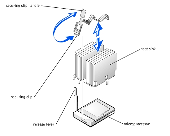
- Push on the heat-sink securing clip handle to release the clip from the retaining tabs
on the ZIF socket (see Figure 6-11).
|
NOTE: The securing clip is spring-loaded and could quickly disengage when removing.
|
- Remove the securing clip.
|
WARNING: The microprocessor and heat sink can become extremely hot. Ensure
that the microprocessor has had sufficient time to cool before handling.
|
|
|
CAUTION: Never remove the heat sink from a microprocessor unless you intend
to remove the microprocessor. The heat sink is necessary to maintain proper
thermal conditions.
|
Figure 6-11. Heat-Sink Securing Clips

- Remove the heat sink.
- Pull the socket release lever straight up until the microprocessor is released (see
Figure 6-12).
- Lift the microprocessor out of the socket and leave the release lever up so that the
socket is ready for the new microprocessor.
|
|
CAUTION: Be careful not to bend any of the pins when removing the
microprocessor. Bending the pins can permanently damage the microprocessor.
|
Figure 6-12. Removing the Microprocessor

- Unpack the new microprocessor.
If any of the pins on the microprocessor appear bent, see "Getting Help," for instructions on obtaining technical assistance.
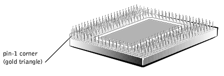
- Align the pin-1 corner of the microprocessor (see Figure 6-13) with the pin-1 corner of
the microprocessor socket.
|
NOTE: Identifying the pin-1 corners is critical to positioning the microprocessor correctly.
|
Identify the pin-1 corner of the microprocessor by locating the tiny gold triangle that extends from one corner of the large central rectangular area. The gold triangle points toward pin 1, which is also uniquely identified by a square pad.
Figure 6-13. Pin-1 Identification
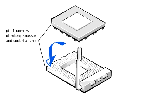
- If the release lever on the microprocessor socket is not all the way up, move it to that
position now.
- Install the microprocessor in the socket (see Figure 6-14).
|
|
CAUTION: Positioning the microprocessor incorrectly can permanently damage
the microprocessor and the system when you turn on the system. When placing
the microprocessor in the socket, ensure that all of the pins on the
microprocessor go into the corresponding holes. Be careful not to bend the pins.
|
- When the microprocessor is fully seated in the socket, rotate the socket release lever
back down until it snaps into place, securing the microprocessor.
Figure 6-14. Installing the Microprocessor
- Place the new heat sink on top of the microprocessor (see Figure 6-15).
- Orient the securing clip as shown in Figure 6-15.
Figure 6-15. Installing the Heat-Sink
- Hook the end of the clip without the heat-sink latch to the tab on the edge of the
socket.
- Align the hole in the heat-sink securing clip with the tab on the edge of the socket, and
push the heat-sink securing clip handle until it snaps into place next to the heat-sink.
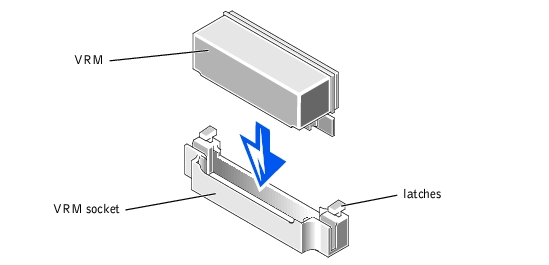
- If you are adding a second microprocessor, install the VRM in the VRM_CONN socket
making sure that the latches engage (see Figure 6-16).
Figure 6-16. Installing the VRM
- Reinstall the microprocessor and memory module cooling shrouds (see "Installing the
Microprocessor and Memory Module Cooling Shrouds").
- Reinstall the system's right-side cover.
- Replace the front bezel.
- Reconnect your system and peripherals to their power sources, and turn on system.
- Press <F2> to enter the System Setup program, and check that the PROCESSOR 1 and
PROCESSOR 2 categories match the new system configuration.
See the system User's Guide for instructions.
- As the system boots, it detects the presence of the new processor and automatically
changes the system configuration information in the System Setup program. If you
installed a second microprocessor, the following message is displayed:
Two 1.13 GHZ Processors, Processor Bus: 133 MHz, L2 cache 512 KB
Advanced
If only one processor is installed, the following message is displayed:
One 1.13 GHz Processor, Processor Bus: 133 MHz, L2 cache 512 KB
Advanced
|
NOTE: After you remove and replace the front bezel, the chassis intrusion detector causes
the following message to display at the next system start-up:
|
ALERT! Bezel was previously removed.
- Enter the System Setup program, and confirm that the top line in the system data area
correctly identifies the installed processor(s). See "Using the System Setup Program"
in your User's Guide.
- While in the System Setup program, reset the chassis intrusion detector.
|
NOTE: If a setup password has been assigned by someone else, contact your network
administrator for information on resetting the chassis intrusion detector.
|
- Run the system diagnostics to verify that the new microprocessor is operating
correctly. See "Running System Diagnostics," for information on running the
diagnostics and troubleshooting any problems that might occur.
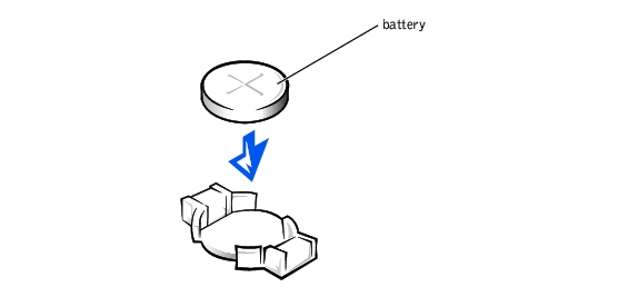
The battery is a 3.0-volt (V), coin-cell battery. To remove the battery, perform the following steps.
|
WARNING: Before you perform this procedure, you must turn off the system and
disconnect it from its power source. For more information, see "Safety First—
For You and Your System" in "Troubleshooting Your System."
|
|
WARNING: There is a danger of a new battery exploding if it is incorrectly
installed. Replace the battery only with the same or equivalent type
recommended by the manufacturer. Discard used batteries according to the
manufacturer's instructions.
|
- Enter the System Setup program and, if possible, make a printed copy of the System
Setup screens.
See "Using the System Setup Program," in the User's Guide for instructions.
- Turn off the system, including any attached peripherals, and disconnect the system
from the electrical outlet.
|
|
CAUTION: See "Protecting Against Electrostatic Discharge" in the safety
instructions in your System Information document.
|
- Remove the system's right-side cover (see "Removing and Replacing the System
Covers" in "Troubleshooting Your System").
- Remove the cooling shrouds (see "Cooling Shrouds").
- Remove the system battery (see Figure 6-1, for the battery location).
You can pry the system battery out of its socket with your fingers or with a blunt, nonconductive object such as a plastic screwdriver.
- Install the new system battery with the side labeled "+" facing up (see Figure 6-17).
Figure 6-17. Installing the System Battery
- Replace the cooling shrouds (see "Cooling Shrouds").
- Replace the system's right-side cover.
- Reconnect the system to an electrical outlet and turn on the system, including any
attached peripherals.
- Enter the System Setup program to confirm that the battery is operating properly.
- Enter the correct time and date through the System Setup program's Time and Date
settings.
Also reenter any system configuration information that is no longer displayed on the System Setup screens, and then exit the System Setup program.
- To test the newly installed battery, power down and disconnect the system from the
electrical source for at least an hour.
- Replace the front bezel.
- After an hour, connect the system to an electrical source and turn on the power.
- Enter the System Setup program and if the time and date are still incorrect, see
"Getting Help," for instructions on obtaining technical assistance.
Back to Contents Page