 Hardware Specifications
Dell™ Remote Access Controller Installation and Setup Guide
Replacing a Battery on a DRAC III
Installing Optional DRAC III Hardware
This section provides information on the hardware attributes and characteristics of the RACs. It also includes information on replacing DRAC III battery packs and installing optional DRAC III hardware such as a PCMCIA modem, external power adapter, and cables.
| Before removing or installing any system component, see the System Information document included with your system for important safety instructions. |
System power:
+2.5 V at 2 A maximum
System power (PCI slot only):
+5 V at 2 A maximum
External AC power adapter capacity:
+6 V at 2.5 A maximum
Battery backup capacity:
1400 mAh (30 minutes of operation)
The DRAC III is compliant with PCI Local Bus Specification 2.1. Table A-1 provides the identification values for the card.
|
Item |
Function |
Value |
|---|---|---|
Subsystem device ID | 0 1 2 | 0x0007 0x0008 0x0009 |
Subsystem vendor ID |
| 0x1028 |
Class code |
| 088000 (generic system peripheral) |
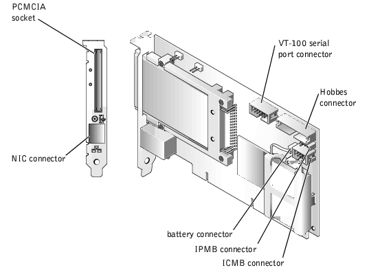
The DRAC III connectors are summarized in Table A-2 and illustrated in Figure A-1.
|
Connector |
Type |
|---|---|
VT-100 serial | 10-pin connector |
ICMB | 6-pin connector |
Hobbes | 20-pin connector |
IPMB | 3-pin connector |
Battery | 2-pin connector |
PCMCIA | 68-pin connector |
NIC | RJ-45 connector |
Figure A-1. DRAC III Connectors
The following sections describe the replacement of the DRAC III battery, including removing and installing the battery pack.
| Before removing or installing any system component, see the System Information document included with your system for important safety instructions. |
The following sections provide procedures for installing DRAC III optional hardware, including: PCMCIA modem, external power adapter, VT-100 cable, and IPMB cable.
Before removing or installing any system component, see the System Information document included with your system for important safety instructions.
To install an optional PCMCIA modem, perform the following steps.

|
CAUTION: The optional PCMCIA modem cannot be installed on the DRAC III while the DRAC III is turned on. To install the optional modem, you must first turn off the system, disconnect the external power adapter from the DRAC III, and remove the DRAC III from the system. These precautions ensure that the integrated battery is not providing power to the DRAC III circuitry. If the DRAC III has been using battery power, it continues to do so for approximately 15 seconds after the DRAC III is removed from its PCI slot. |
While the DRAC III does not require an external power adapter, using one will allow the DRAC III to remain operational when the system is off, and will extend the DRAC III power beyond the 30-minute limit of the lithium ion battery pack. For power supply specifications, see "DRAC III Power Requirements."
To install the external power adapter, perform the following steps:
For information on installing your optional VT-100 cable, see the Information Update that is included in your VT-100 serial cable kit.
The DRAC III is equipped with a 3-pin cable that allows access to the system's IPMB on 64-bit systems only. The IPMB provides remote monitoring, log in, and recovery control functions independent of the main processors, BIOS, and operating system. The IPMB is available for remote monitoring even when the system is turned off.
 |
NOTICE: The IPMB cable must first be attached to the DRAC III before connecting it to the system. |
 |
NOTE: If you are unsure if your system is equipped with a 3-pin IPMB connector, see your system documentation before proceeding with the installation. |
To install the IPMB cable, perform the following steps: