 Installing a DRAC III
Dell™ Remote Access Controller Installation and Setup Guide
Uninstalling the DRAC III or ERA/O
This section provides procedures for installing the Dell™ Remote Access Card III (DRAC III) and the Dell Embedded Remote Access Option (ERA/O) in your system.
 |
NOTICE: Before installing a DRAC III, read the installation instructions in this document and in your system's Installation and Troubleshooting Guide. |
| Before beginning the installation, carefully read the safety instructions in your System Information document included with your system. |

|
CAUTION: Following these steps reduces the potential for personal injury or shock. |
|
|
CAUTION: The power supplies in your system or storage system may produce high voltages and energy hazards, which can cause bodily harm. Only trained service technicians are authorized to remove the system covers and access any of the components inside the system. |
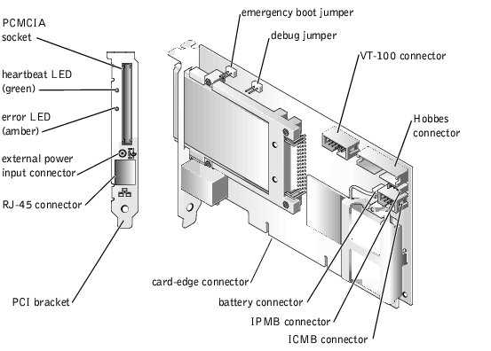
Figure 2-1. DRAC III Hardware Components
|
NOTICE: If you are installing the DRAC III on a 32-bit system, skip steps 7 and 8. If you are installing the DRAC III on a 64-bit system and want access to the IPMB, you must complete steps 7 and 8 before installing the DRAC III in the system. The IPMB allows remote monitoring, logging, and recovery control functions independent of the main processors, BIOS, and operating system. The IPMB is available for remote monitoring even when the system is turned off. |
Ensure that the cable is securely connected to the DRAC III card. The other end of the cable is connected to the system backplane described in step 8.
See your system Installation and Troubleshooting Guide for the location of this connector.
|
NOTICE: The DRAC III must be inserted into PCI slot 1 because it must reside on the same bus as the video controller. If another expansion card is installed in slot 1, it must be moved to another slot before proceeding with the installation. |
|
NOTICE: On PowerEdge™ 1650 systems, the DRAC III is installed on a riser board. The riser board plugs into the RISER connector on the system board and is considered an extension of the system board. Two riser board configurations exist for the PowerEdge 1650. The first features two 64-bit, 66-MHz expansion slots (PCI1 and PCI2). The second features one 64-bit, 66-MHz expansion slot (PCI2) and one 32-bit, 33-MHz expansion slot (PCI1) for 5-V cards. For the DRAC III to function properly, it must be installed in the PCI1 slot. If you purchased the DRAC III with your PowerEdge 1650, the riser card and the DRAC III are preinstalled. If you purchased the DRAC III kit separately for installation on a PowerEdge 1650, see the instructions for installing the riser card contained in the kit. |
Ensure that the card-edge connector is fully seated into the system board.
|
NOTICE: You must use the DRAC III VT-100 serial cable specifically provided for use with the DRAC III because not all serial cables have the same pin-out specification. Using the wrong cable will result in VT-100 terminal emulation failure or DRAC III failure. |
|
NOTICE: While the DRAC III does not require an external power adapter, using one allows the DRAC III to remain operational when the system is off, and extends the DRAC III power beyond the 30-minute capability of the battery pack. |
 |
NOTE: A UPS is recommended for the most complete power protection. |
|
NOTE: The maximum length allowed for the LAN cable connected to the RJ-45 connector is 184 ft (56 m). |
If the DRAC III installation was successful, the green heartbeat LED indicator on the back of the card connector is illuminated (see "DRAC III LED Indicators").
|
|
CAUTION: Before you perform this procedure, you must turn off the system and disconnect it from its power source. Only trained service technicians are authorized to remove the system cover and access any of the components inside the system. Read and follow all safety precautions in your System Information document. |
|
|
CAUTION: Your system may have more than one power supply cable. To reduce the risk of electrical shock, a trained service technician must disconnect all power supply cables before servicing the system. For more information, see "Safety First—For You and Your Computer" in your Installation and Troubleshooting Guide. |
|
NOTE: You can install only half-length PCI cards in your system if an ERA/O card is installed. The system cannot physically accommodate the ERA/O card and a full- length PCI card. |
|
NOTE: Installing a filler bracket over an empty expansion slot is necessary to maintain Federal Communications Commission (FCC) certification of the system. The brackets also keep dust and dirt out of the system and aid in proper cooling and airflow inside the system. |
Figure 2-2. Removing a Full-Length Expansion Card (If Installed)
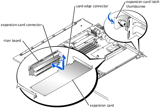
Figure 2-3. Installing the ERA/O Card
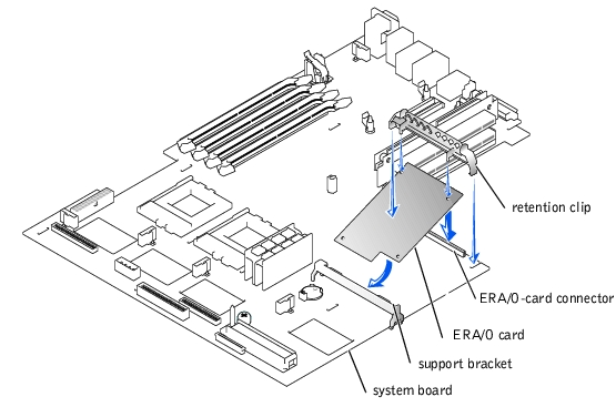
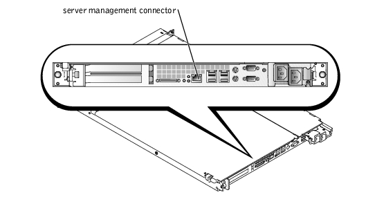
Figure 2-4. Server Management Connector
For information on the ERA/O remote management software, see the remote access controller documentation provided on the online documentation CD.
To uninstall the DRAC III or ERA/O from your system, follow the instructions for installing the DRAC III or ERA/O in the previous sections, and then uninstall the components and cables in the reverse order that they were installed.