Front-Panel Indicators and Features
Dell™ PowerEdge™ 2600 Systems Service Manual
|
|
Applications, operating systems, and the system itself are capable of identifying problems and alerting you to them. When a problem occurs, a message may appear on the monitor, or a beep code may sound.
A variety of indicators, codes, and messages can alert you when the system is not functioning properly:
The system indicators and features are illustrated in Figure 3-1 through Figure 3-6. This section also describes each type of message, and lists the possible causes and actions you can take to resolve any problems indicated by a message. To determine what type of message you have received, read the following subsections.
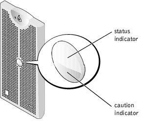
The system has indictors that can represent system status. When the bezel is installed, the bezel system-status indicator (see Figure 3-1) signifies when the system is operating properly or when the system needs attention. A caution code signifies a problem with microprocessors, power supply, system or power-supply fans, system temperature, hard drives, system memory, expansion cards, or the integrated SCSI controller. When the bezel is off, the system status indicators on the system (see Figure 3-2) assumes the same functions as the bezel system status indicator.
Table 3-1 lists the system's status indicator codes.
Figure 3-1. System-Status Indicators
|
Bezel Indicators |
Indicator Code | |
|---|---|---|
|
Status |
Caution | |
Off | Off | No power is available to the system, or the system is not powered on. |
On | Off | The system is operating normally. |
Off | Blinking | The system has detected an error and requires attention. |
Blinking | Off | The system is identifying itself (see "Front-Panel Indicators and Features"). |
Blinking | Blinking or Off | Systems management software causes the status indicator to blink to identify a particular system. |
Additional indicators are located behind the bezel on the power supplies, hard drives, and the control panel. The CD and diskette drives have green activity indicator.s
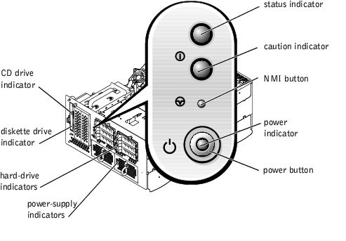
Figure 3-2 shows the front-panel indicators and features of the system. Table 3-2 describes the front-panel features.
Figure 3-2. Front-Panel Indicators and Features
|
Component |
Description | ||
|---|---|---|---|
Power button | Turns system power off and on.
The button is enabled in the System Setup program. When disabled, the button can only turn system power on. For more information, see the User's Guide and the operating system's documentation. | ||
Power indicator | Provides information on power status (see "Power Indicator Codes"). | ||
Power-supply indicators | Provide information on power status (see "Power-Supply Indicator Codes"). | ||
CD and diskette drive indicators | Indicates read or write access to the respective drive. | ||
Hard-drive indicators | Provide information on the status of the respective hard drive (see "Hard-Drive Indicator Codes"). | ||
NIC indicators | Indicate whether the NIC has a valid link to the network (see "NIC Indicator Codes"). | ||
NMI button | Troubleshoots software and device driver errors when using certain operating systems. You can press this button using the end of a paper clip. The NMI option is enabled in the System Setup program.
|
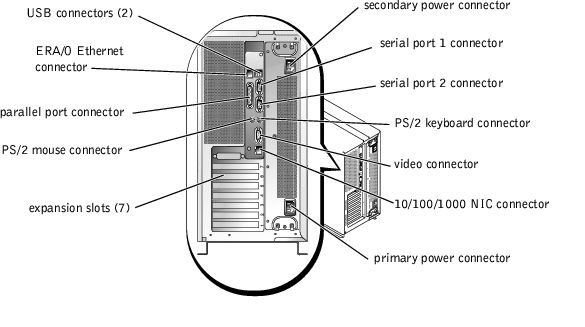
Figure 3-3 shows the back-panel features of the system. Table 3-3 describes the back-panel features.
Figure 3-3. Back-Panel Features
|
Component |
Description |
|---|---|
NIC indicators | Provides information on NIC status (see "NIC Indicator Codes"). |
ERA/O Ethernet connector indicators | Provides information about the ERA/O Ethernet connector status (see "ERA/O Ethernet Connector Indicator Codes"). |
The system has indicators on the power button and on the power supplies that signify system power status.
The power button controls the power input to the system's power supplies. The power-button indicator can provide information on power status (see Figure 3-2).
Table 3-4 lists the power-button indicator codes.
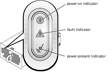
Each hot-pluggable power supply has indicators that can provide information on power status, fault, and the presence of power (see Figure 3-4). Table 3-5 lists the power-supply indicator codes.
Figure 3-4. Power-Supply Indicators
Each hard-drive carrier has two indicators: a busy indicator and a status indicator (see Figure 3-5). The indicators provide information on the status of the respective hard drive. Table 3-6 lists the drive indicator codes.
Figure 3-5. Hard-Drive Indicators
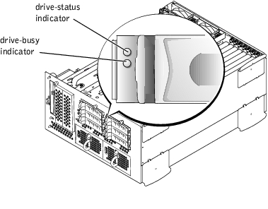
Table 3-6 lists the drive indicator codes. Different codes display as drive events occur in the system. For example, in the event of a hard-drive failure, the "drive fail" code appears. After the drive is selected for removal, the "preparing for removal" code appears. After the replacement drive is installed, the "preparing for operation, drive online" code appears.
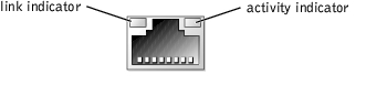
Each NIC on the back panel has an indicator that provides information on network activity and link status (see Figure 3-6). Table 3-7 lists the NIC indicator codes on the back panel.
The front panel has a link indicator for each NIC (see Figure 3-2). Each indicator signifies whether the corresponding NIC is connected to a valid link partner on the network.

The optional embedded remote access (ERA/O) Ethernet connector indicators on the back panel provide information on network activity and link status for the ERA/O Ethernet connector (see Figure 3-7). Table 3-8 lists the ERA/O Ethernet connector indicator codes.
Figure 3-7. ERA/O Ethernet Connector
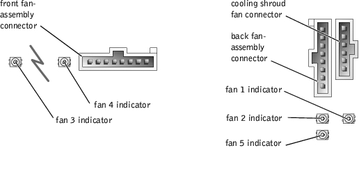
Each individual fan has a status indicator adjacent to the fan connectors on either the system board or on the SCSI backplane board (see Figure 3-8). To locate the fan connectors on the system board, see Figure 5-2. To locate the fan connector on the SCSI backplane board, see Figure 5-4. Table 3-9 lists the cooling fan indicator codes.
Figure 3-8. Cooling Fan Status Indicators
|
Indicator |
Indicator Code |
|---|---|
Off | The fan is not installed. |
Green | The fan is operating normally. |
Amber blinking | The fan is malfunctioning. |
When an error that cannot be reported on the monitor occurs during a boot routine, the system may emit a series of beeps that identifies the problem.
When a beep code is emitted, make a note of it and then look it up in Table 3-10. If you are unable to resolve the problem by looking up the meaning of the beep code, use the system diagnostics to identify a more serious cause.
 |
NOTE: If the system boots without a keyboard, mouse, or monitor attached, the system will not issue beep codes related to those peripherals. |
|
NOTE: Before you perform any procedures described in Table 3-10, see "External Visual Inspection." |
|
Code |
Cause |
Corrective Action |
|---|---|---|
1-1-2 | CPU register test failure. | Replace microprocessor 0. See "Microprocessors." If the problem persists, replace microprocessor 1. |
1-1-3 | CMOS write/read failure; faulty system board. | Replace the system board (see "System Board"). |
1-1-4 | BIOS error. | Reflash the BIOS firmware. Download the latest firmware from the Dell Support website at support.dell.com. |
1-2-1 | Programmable interval-timer failure; faulty system board. | Replace the system board (see "System Board"). |
1-2-2 | DMA initialization failure. | Ensure that the memory modules are properly installed. If the problem persists, replace the faulty memory module(s) (see "Memory Modules"). |
1-2-3 | DMA page register write/read failure. | |
1-3-1 | Main-memory refresh verification failure. | |
1-3-2 | No memory installed. | |
1-3-3 | Chip or data line failure in the first 64 KB of main memory. | |
1-3-4 | Odd/even logic failure in the first 64 KB of main memory. | |
1-4-1 | Address line failure in the first 64 KB of main memory. | |
1-4-2 | Parity failure in the first 64 KB of main memory. | |
1-4-3 | Fail-safe timer test failure. | |
1-4-4 | Software NMI port test failure. | |
2-1-1 through | Bit failure in the first 64 KB of main memory. | |
3-1-1 | Slave DMA-register failure. | Replace the system board (see "System Board"). |
3-1-2 | Master DMA-register failure. | |
3-1-3 | Master interrupt-mask register failure. | |
3-1-4 | Slave interrupt-mask register failure. | |
3-2-2 | Interrupt vector loading failure. | |
3-2-4 | Keyboard-controller test failure. | Check the keyboard cable and connector. If the problem persists, replace the keyboard. If the problem persists, replace the system board (see "System Board"). |
3-3-1 | CMOS failure. | Replace the system board (see "System Board"). |
3-3-2 | System configuration check failure. | |
3-3-3 | Keyboard controller not detected. | |
3-3-4 | Video memory test failure. | |
3-4-1 | Screen initialization failure. | |
3-4-2 | Screen-retrace test failure. | |
3-4-3 | Video ROM search failure. | |
4-2-1 | No timer tick. | |
4-2-2 | Shutdown test failure. | |
4-2-3 | Gate A20 failure. | |
4-2-4 | Unexpected interrupt in protected mode. | Ensure that the expansion cards are properly installed. If the problem persists, replace the faulty expansion card(s) (see "Expansion Cards"). |
4-3-1 | Improperly installed or faulty memory modules. | Ensure that the memory modules are properly installed. If the problem persists, replace the faulty memory module(s) (see "Memory Modules"). |
4-3-2 | No memory modules installed in bank 1. | Install memory modules in bank 1 of the same type and size (see "Installing Memory Modules"). |
4-3-3 | Faulty system board. | Replace the system board (see "System Board"). |
4-3-4 | Time-of-day clock stopped. | Ensure that the system battery is properly installed. If the problem persists, replace the battery (see "System Battery"). |
4-4-1 | Super I/O chip failure; faulty system board. | Replace the system board (see "System Board"). |
4-4-2 | BIOS-shadowing failure. | Ensure that the system cooling fans are properly installed. If the problem persists, replace the faulty fan(s) (see "System Fans"). If the problem persists, replace the system board (see "System Board"). |
4-4-3 | Microprocessor speed control sequence failure. | Ensure that the microprocessors are properly installed. If the problem persists, replace the faulty microprocessor(s) (see "Microprocessors"). If the problem persists, replace the system board (see "System Board"). |
4-4-4 | Cache test failure; faulty microprocessor. |
System messages appear on the monitor during POST to notify you of a possible problem with the system. If you are performing console redirection, system messages will appear on the remote console. Table 3-11 lists the system messages that can occur and the probable cause for each message.
|
NOTE: If you receive a system message that is not listed in Table 3-11, check the documentation for the application program that is running when the message appears or the operating system's documentation for an explanation of the message and recommended action. |
|
Message |
Causes |
Corrective Actions |
|---|---|---|
Address mark not found | Faulty CD/diskette drive subsystem or hard-drive subsystem; faulty system board. | Replace the faulty drive(s) (see "Replacing the CD/Diskette Drive" and "Hard Drives"). If the problem persists, replace the system board (see "System Board"). |
Alert! All memory in the system must have the same primary SDRAM width. The following memory DIMMs have been disabled: DIMMnX. | Memory modules installed are not the same type and size in all banks; faulty memory module(s). | Ensure that all banks contain memory modules of the same type and size and that they are properly installed. If the problem persists, replace the faulty memory module(s) (see "Memory Modules"). |
Alert! Unsupported memory or incomplete sets in the following bank(s): Bank DIMMnX | Memory modules installed in the specified bank(s) are not the same type and size; faulty memory module(s). | Ensure that all banks contain memory modules of the same type and size and that they are properly installed. If the problem persists, replace the faulty memory module(s) (see "Memory Modules"). |
Amount of available memory limited to 256 MB! | OS Install Mode is enabled in the System Setup program. | Disable OS Install Mode in the System Setup program (see "Using the System Setup Program"). |
Auxiliary device failure | Loose or improperly connected mouse or keyboard cable; faulty mouse or keyboard. | Check the mouse and keyboard cables and connectors. If the problem persists, replace the mouse and keyboard. If the problem persists, replace the system board (see "System Board"). |
BIOS Update Attempt Failed! | Remote BIOS update attempt failed. | Retry the BIOS update. Download the latest firmware from the Dell Support website at support.dell.com. |
CD-ROM drive not found | Improperly connected or missing CD/diskette drive. | Ensure that the CD/diskette drive is properly installed. If the problem persists, replace the CD/diskette drive (see "CD/Diskette Drive"). |
CPUs with different cache sizes detected | Microprocessors with different cache sizes are installed. | Ensure that all microprocessors have the same cache size and that they are properly installed (see "Memory Modules"). |
Decreasing available memory | Faulty or improperly installed memory modules. | Ensure that the memory modules are properly installed. If the problem persists, replace the faulty memory module(s) (see "Memory Modules"). |
Diskette drive n seek failure | Incorrect configuration settings in the System Setup program. Faulty or improperly installed diskette drive. | Run the System Setup program to correct the settings (see "Using the System Setup Program"). Ensure that the diskette drive is properly installed. If the problem persists, replace the diskette drive (see "SCSI Configuration Information"). |
Diskette read failure | Faulty or improperly inserted diskette. | Replace the diskette. |
Diskette subsystem reset failed | Faulty or improperly installed diskette drive. | Ensure that the diskette drive is properly installed. If the problem persists, replace the diskette drive (see "SCSI Configuration Information"). |
ECC memory error | Faulty or improperly installed memory modules. | Ensure that the memory modules are properly installed. If the problem persists, replace the faulty memory module(s) (see "Memory Modules"). |
Embedded server management error Embedded server management is not present. | Embedded server management memory may be temporarily corrupted | To clear the embedded remote access memory, shut down the system, disconnect the power cords, wait approximately 30 seconds, reconnect the power cords, and restart the system. If the problem persists, replace the ERA/O card (see "ERA/O Card"). |
Error: Maximum PCI option ROM count exceeded! | Too many expansion cards have ROM enabled in the System Setup program. | Disable ROM for some of the expansion cards (see "Using the System Setup Program"). |
Gate A20 failure | Faulty keyboard controller; faulty system board. | Replace the system board (see "System Board"). |
Hard disk controller failure Hard disk read failure | Incorrect configuration settings in System Setup program; improperly installed hard drive, or loose interface or power cable; faulty hard-drive controller subsystem. | Run the System Setup program to correct the drive type (see "Using the System Setup Program"). If the problem persists, ensure that the hard drives are properly installed (see "Hard Drives"). If the problem persists, replace the system board (see "System Board"). |
I/O parity interrupt at address | Faulty or improperly installed expansion card. | Ensure that the expansion cards are properly installed. If the problem persists, replace the faulty expansion card(s) (see "Expansion Cards"). |
Invalid configuration information - please run SETUP program | Incorrect configuration settings in System Setup program; NVRAM_CLR jumper is installed; faulty system battery. | Check the System Setup configuration settings (see "Using the System Setup Program"). Remove the NVRAM_CLR jumper (see Figure 5-2 for jumper location). If the problem persists, replace the system battery (see "System Battery"). |
Invalid memory configuration detected; potential for data corruption exists | Faulty or improperly installed memory modules. | Memory modules must be populated in the following order: DIMM_1A and DIMM_1B must be in the first slots populated; DIMM_2A and DIMM_2B must be in the second slots populated, and so on. Remove and reseat the DIMMs in their sockets. If the problem persists, replace the memory module ("Memory Modules"). |
Invalid NVRAM configuration, resource re-allocated | System configuration data has been ignored. | Check the System Setup configuration settings (see "Using the System Setup Program"). |
Invalid SCSI configuration; SCSI cable not detected on connector SCSIB of the primary SCSI backplane, daughter card present
| A SCSI cable is not connected to the channel B connector on the SCSI backplane board; SCSI backplane daughter card is installed.
| If a cable is connected to the SCSIB backplane board connector, the SCSI backplane daughter card must be installed. Install the SCSI cable to SCSIB backplane board connector (see "Installing the SCSI Backplane Daughter Card"). If a cable is connected to the SCSIB backplane board connector, the SCSI backplane daughter card must be installed. Install the backplane daughter card (see "Installing the SCSI Backplane Daughter Card"). |
Keyboard controller failure | Faulty keyboard controller; faulty system board. | Replace the system board (see "System Board"). |
Keyboard clock line failure Keyboard data line failure Keyboard failure Keyboard stuck key failure | Loose or improperly connected keyboard cable; faulty keyboard; faulty keyboard controller. | Check the keyboard cable and connector. If the problem persists, replace the keyboard. If the problem still persists, replace the system board (see "System Board"). |
Memory address line failure at address, read value expecting value Memory double word logic failure at address, read value expecting value Memory high address line failure at start address to end address Memory high data line failure at start address to end address Memory odd/even logic failure at start address to end address Memory parity failure at start address to end address Memory parity error at address Memory write/read failure at address, read value expecting value | Faulty or improperly installed memory modules. | Ensure that the memory modules are properly installed. If the problem persists, replace the faulty memory module(s) (see "Memory Modules"). |
No boot device available | Faulty or missing CD/diskette drive subsystem, hard drive, or hard-drive subsystem. | Check the boot device configuration settings in the System Setup program for Integrated Devices (see "Using the System Setup Program"). If they were disabled, enable them and reboot. Use a bootable diskette, CD, or hard drive. If booting from a SCSI controller, ensure that the controller is properly connected. If the problem persists, replace the faulty drive(s) (see "CD/Diskette Drive" and "Hard Drives"). If the problem still persists, replace the system board (see "System Board"). |
No boot sector on hard- disk | No operating system on hard drive. | Check the hard-drive configuration settings in the System Setup program (see "Using the System Setup Program"). |
No PXE-capable device available | <F12> pressed during POST and no PXE devices are detected. | Check the configuration settings in the System Setup program for the NICs (see "Using the System Setup Program"). |
No timer tick interrupt | Faulty system board. | Replace the system board (see "System Board"). |
Not a boot diskette | No operating system on diskette. | Use a bootable diskette. |
PCI BIOS failed to install | Loose cables to expansion card(s); faulty or improperly installed expansion card. | Ensure that cables to expansion cards are properly connected. Ensure that the expansion cards are properly installed. If the problem persists, replace the faulty expansion card(s) (see "Expansion Cards"). |
Plug & Play Configuration Error Embedded xxx Plug & Play Configuration Error PCI_n | Error encountered in initializing PCI device; faulty system board. Error encountered in initializing PCI adapter. | Install the NVRAM_CLR jumper and reboot the system (see Figure 5-2 for jumper location). If the problem persists, ensure that the expansion cards are properly installed. If the problem still persists, replace the faulty expansion card(s) (see "Expansion Cards"). If the problem still persists, update the BIOS firmware. Download the latest firmware from the Dell Support website at support.dell.com. |
Primary backplane is not present | Faulty or improperly installed SCSI backplane board. | Ensure that the SCSI backplane board is properly installed. If the problem persists, replace the backplane board (see "SCSI Backplane Board"). |
Processor n internal error Processor bus parity error | Faulty microprocessor; faulty system board. | Ensure that the microprocessors are properly installed. If the problem persists, replace the faulty microprocessor(s) (see "Microprocessors"). If the problem persists, replace the system board (see "System Board"). |
Processor in socket 1 not installed! | No microprocessor installed in primary microprocessor socket. | Install a microprocessor in the primary microprocessor socket. Also, ensure that a VRM for processor 1 is installed (see "Microprocessors"). |
SCSI cable not present on connector SCSIA of the primary backplane | SCSI cable is loose, improperly connected, or faulty. | Ensure that the SCSI cables are properly installed. If problem persists, add or replace the cables. |
Shutdown failure | Shutdown test failure. | Ensure that the memory modules are properly installed. If the problem persists, replace the faulty memory module(s) (see "Memory Modules"). |
System backplane error | Faulty or improperly installed SCSI backplane board. | Ensure that the SCSI backplane board is properly installed. If the problem persists, replace the backplane board (see "SCSI Backplane Board"). |
System halted! Must power down | Wrong password entered too many times. | Information only. |
Time-of-day clock stopped | Faulty battery. | Ensure that the system battery is properly installed. If the problem persists, replace the battery (see "System Battery"). |
Time-of-day not set - please run SETUP program | Incorrect Time or Date settings; faulty system battery. | Check the Time and Date settings (see "Using the System Setup Program"). If the problem persists, replace the system battery (see "System Battery"). |
Timer chip counter 2 failed | Faulty system board. | Replace the system board (see "System Board"). |
Unsupported CPU combination Unsupported CPU stepping detected | Microprocessor(s) is not supported by the system. | Update the BIOS firmware. Download the latest firmware from the Dell Support website at support.dell.com. If the problem persists, install a supported microprocessor combination (see "Microprocessors"). |
Unsupported DIMM detected in the RAID DIMM slot! | RAID memory module is not supported by the system. | Install a correct version of the RAID memory module (see "Activating the Integrated RAID Controller"). |
Unsupported RAID key detected! | RAID hardware key is not supported by the system. | Install the RAID hardware key for your specific system (see "Activating the Integrated RAID Controller"). |
Utility partition not available | <F10> was pressed during POST, but no utility partition exists on the boot hard drive. | Create a utility partition on the boot hard drive (see "Using the Dell OpenManage Server Assistant CD" in your User's Guide). |
The VRM for the processor in socket n is not installed. | Specified microprocessor VRM is faulty, unsupported, improperly installed, or missing. | A VRM must be installed for each installed microprocessor. Install a VRM for the specified microprocessor or remove the VRM for the specified microprocessor if that microprocessor is not installed (see "Microprocessors"). To identify the microprocessors and VRMs, see Figure 5-2. |
Warning: Detected mode change from RAID to SCSI B of the embedded RAID subsystem. Warning: Detected missing RAID hardware for the embedded RAID subsystem. Data loss will occur! Press Y to switch mode to SCSI, press any other key to disable both channels. Press Y to confirm the change; press any other key to cancel. | Type of controller has changed since previous system boot. | Back up information on the hard drives before changing the type of controller used with the drives. |
Warning: Firmware is out- of-date, please update. | Firmware error. | Update the firmware. Download the latest firmware from the Dell Support website at support.dell.com. |
Warning! No microcode update loaded for processor n | BIOS error. | Update the BIOS firmware. Download the latest firmware from the Dell Support website at support.dell.com. |
Warning! System FRU is not programmed | Faulty or corrupt data in NVRAM. | Ensure that the system board is properly installed and configured. If the problem persists, replace the system board (see "System Board"). |
Write fault Write fault on selected drive | Faulty diskette, CD/diskette drive assembly, hard drive, or hard-drive subsystem. | Replace the faulty drive (see "CD/Diskette Drive" and "Hard Drives"). If the problem persists, replace the system board (see "System Board"). |
A warning message alerts you to a possible problem and asks you to take corrective action before the system continues a task. For example, before you format a diskette, a message may warn you that you may lose all data on the diskette. Warning messages usually interrupt the procedure and require you to respond by typing y (yes) or n (no).
|
NOTE: Warning messages are generated by either the application program or the operating system. For more information, see the documentation that accompanied the operating system or application program. |
When you run a test group or subtest in system diagnostics, an error message may result. Diagnostic error messages are not covered in this section. The message usually provides information for identification of the faulty component.
The optional systems management software generates alert messages for your system. For example, the software generates messages that appear in the SNMP trap log file. Alert messages consist of information, status, warning, and failure messages for drive, temperature, fan, and power conditions. For more information, see the systems management software documentation.

|
CAUTION: The power supplies in this system produce high voltages and energy hazards, which can cause bodily harm. Only trained service technicians are authorized to remove the system cover and access any of the components inside the system. |
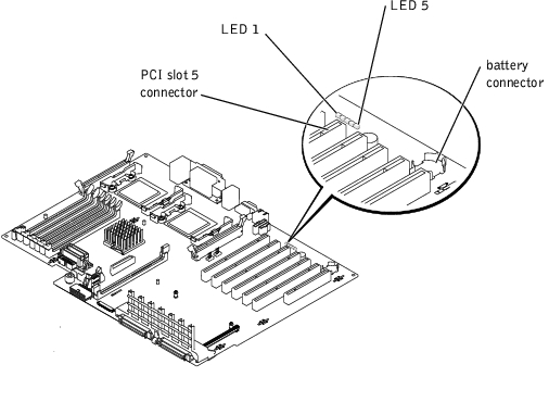
Errors that cannot be reported on the monitor during the boot routine can appear on the system board as a series of five lit or flashing LEDs. The LEDs can only be seen when the system cover is removed (see Figure 3-9). Table 3-12 defines these LED codes.