Back to Contents Page
Dell™ PowerEdge™ 2600 Systems
Service Manual
The procedures in this guide require that you remove the cover and work inside the system. While working inside the system, do not attempt to service the system except as explained in this manual and elsewhere in your system documentation. Always follow the instructions closely. Review all of the procedures in the System Information Guide.

|
CAUTION: Only trained service technicians are authorized to remove the system cover and access any of the components inside the system. See your System Information Guide for complete information about safety precautions, working inside the computer, and protecting against electrostatic discharge. |
This section provides servicing procedures for components inside the system. Before you start any of the procedures in this section, perform the following tasks:
|
|
Read the safety information in the System Information Guide. |
When there is no replacement procedure provided, use the removal procedure in reverse order to install the replacement part.
You need the following items to perform the procedures in this section:
- Key to the system keylock
- #2 Phillips screwdriver
- Wrist grounding strap
Figure 4-1 shows the rack and tower versions of the system. The illustrations in this document depict the tower version of the system lying on its side.
Figure 4-1. System Orientation
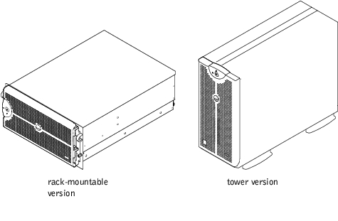
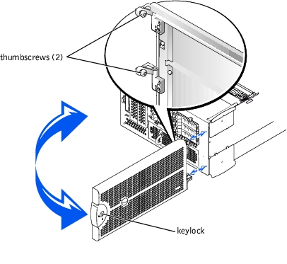
The bezel has a system status indicator. A lock on the bezel restricts access to the power button, diskette drive, CD drive, hard drive(s), power supplies, and the interior of the system. You must open or remove the bezel and remove the system cover to gain access to internal components.
- Using the system key, unlock the bezel.
- Press the tab at the left end of the bezel.
- Pull the bezel away from the system so that it is perpendicular to the system (see
Figure 4-2).
- Loosen the thumbscrews to release the bezel (see Figure 4-2).
- Pull the bezel away from the chassis.
Figure 4-2. Removing the Bezel
- Align the two thumbscrews with the mounting holes on the front of the system.
- Tighten the thumbscrews to secure the bezel (see Figure 4-2).
- Swing the bezel closed until it snaps into place.
- Using the system key, lock the bezel.
To upgrade or troubleshoot the system, remove the system cover to gain access to internal components.
|
|
CAUTION: Only trained service technicians are authorized to remove the system cover and access any of the components inside the system. See your System Information Guide for complete information about safety precautions, working inside the computer, and protecting against electrostatic discharge. |
- Remove the bezel (see "Removing the Bezel").
- Turn off the system, including any attached peripherals, and disconnect the system
from the electrical outlet.
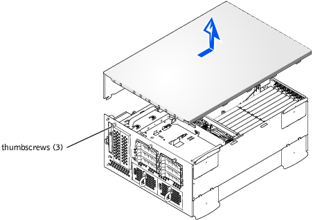
- Loosen the three thumbscrews on the front of the system (see Figure 4-3).
- Slide the system cover backward and grasp the cover at both ends.
- Carefully lift the cover away from the system.
Figure 4-3. Removing the Cover
- Ensure that no tools or parts are left inside the system and that any cables are routed
so that they will not be damaged by the cover.
- Align the cover with the cover alignment hooks on the sides of the chassis, and slide
the cover forward (see Figure 4-3).
- Tighten the three thumbscrews that secure the cover to the chassis.
- Replace the bezel (see "Replacing the Bezel").
In Figure 4-4, the covers and bezel are removed to provide an interior view of the system.
Figure 4-4. Inside the System
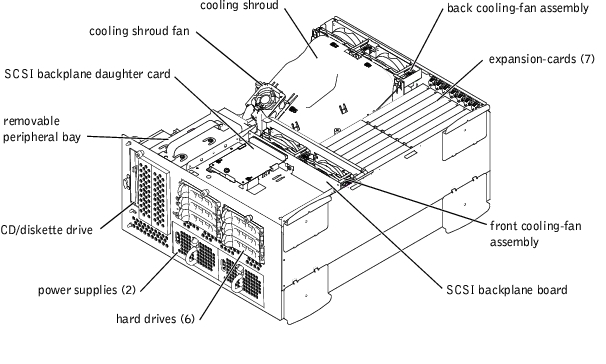
The system board holds the system's control circuitry and other electronic components. Several hardware options, such as the microprocessors and memory, are installed directly on the system board. The system board can accommodate up to seven PCI or PCI-X expansion cards (two PCI or PCI-X cards at 64-bit/33-133 MHz, four PCI or PCI-X cards at 64-bit/33-100 MHz, and one PCI card at 32-bit/33 MHz).
The peripheral bay provides space for a 3.5-inch diskette drive, a CD drive, and two hard drives.The hard-drive bays provide space for up to five 1-inch SCSI hard drives. The hard drives connect to a controller on the system board or a RAID controller card through the SCSI backplane board. For more information, see "Hard Drives."
The hard-drive bays provide space for up to six 1-inch hard drives. These hard drives are connected to a SCSI host adapter on the system board or on an expansion card, by way of the SCSI backplane board.
The power supply distribution board (PSDB) provides power distribution for the system. One front-loadable power supply slides into connectors mounted on the PSDB to provide power to the system board and internal peripherals. An option for a second hot-pluggable power supply to provide redundant power is available.
For non-SCSI drives such as the diskette drive and CD drive, an interface cable connects the interposer board, attached to the diskette drive and CD drive, to the system board. For SCSI devices, interface cables connect externally accessible SCSI devices and the SCSI backplane board to a SCSI host adapter either on the system board or on an expansion card. For more information, see "Installing a Hard Drive."
During an installation, repair, or troubleshooting procedure, you may be required to change a jumper. For information on the system board jumpers, see "Jumpers and Connectors."
|
|
CAUTION: Only trained service technicians are authorized to remove the system cover and access any of the components inside the system. See your System Information Guide for complete information about safety precautions, working inside the computer, and protecting against electrostatic discharge. |
- Remove the bezel (see "Removing the Bezel").
- Remove the system cover (see "Removing the Cover").
- Disconnect the CD/diskette drive cable from the back of the CD/diskette drive (see
Figure 4-5).
The other end of this cable connects to the system board.
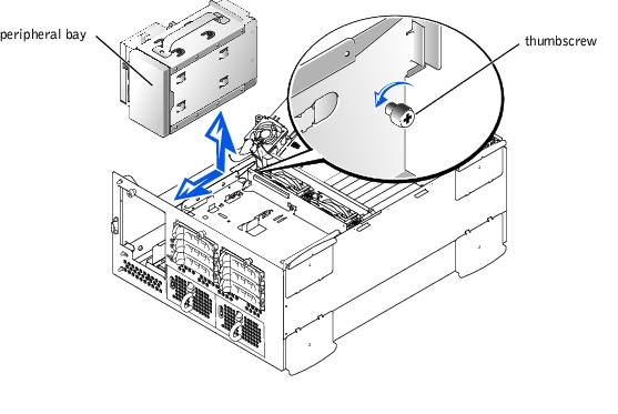
- Disconnect any cables from any devices already installed in the peripheral bay.
- Loosen the thumbscrew securing the back of the peripheral bay to the chassis.
- Grasping the peripheral bay by its top handle with one hand and pressing the front of
the peripheral bay, slide the peripheral bay backward approximately 0.5-inch and lift
up to remove the peripheral bay from the chassis.
Figure 4-5. Peripheral Bay Replacement
- Holding the peripheral bay by its top handle, lower it into place and slide it forward
approximately 0.5-inch (see Figure 4-5).
The front panel of the peripheral bay, with its attached CD/diskette drive, must be flush with the front panel.
- Connect the CD/diskette drive cable to the back of the interposer board (see
Figure 4-5).
- Connect any cables you removed from any devices already installed in the peripheral
bay.
- Tighten the thumbscrew to secure the peripheral bay to the chassis (see Figure 4-5).
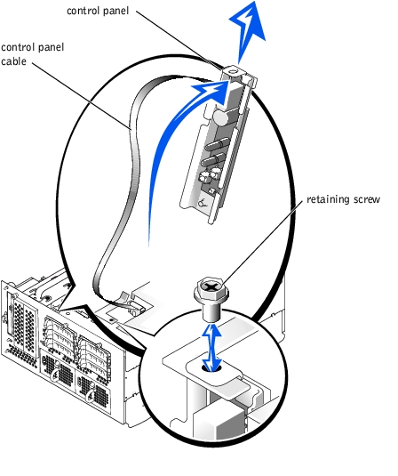
In Figure 4-6, the control panel is shown removed from the system chassis.
Figure 4-6. Control-Panel Removal
|
|
CAUTION: Only trained service technicians are authorized to remove the system cover and access any of the components inside the system. See your System Information Guide for complete information about safety precautions, working inside the computer, and protecting against electrostatic discharge. |
- Remove the bezel (see "Removing the Bezel").
- Remove the system cover (see "Removing the Cover").
- Disconnect the control panel cable from the system board (see Figure 5-3 for
location).
- Remove the retaining screw that secures the control-panel assembly to the system
chassis (see Figure 4-6).
- Move the control panel back and lift it up and out of the front panel.
- Lift the control panel and its cable completely out of the chassis (see Figure 4-6).
|
|
CAUTION: Only trained service technicians are authorized to remove the system cover and access any of the components inside the system. See your System Information Guide for complete information about safety precautions, working inside the computer, and protecting against electrostatic discharge. |
- Lower the control-panel and its cable into the system.
- Connect the control-panel cable to the system board (see Figure 5-3 for location).
- Slide the assembly towards the front panel (see Figure 4-6).
- Install the retaining screw that secures the control-panel assembly to the front panel
(see Figure 4-6).
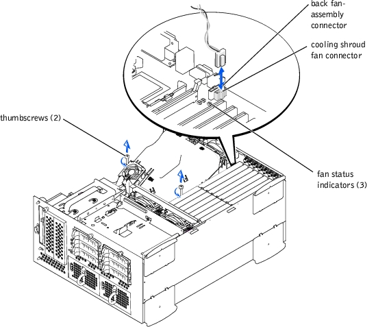
The cooling shroud is attached to the back fan assembly and secured to the system board with two thumbscrews.
|
|
CAUTION: Only trained service technicians are authorized to remove the system cover and access any of the components inside the system. See your System Information Guide for complete information about safety precautions, working inside the computer, and protecting against electrostatic discharge. |
- Open the bezel (see "Removing the Bezel").
- Turn off the system, including any attached peripherals, and disconnect the system
from the electrical outlet.
- Remove the cover (see "Removing the Cover").
- Disconnect the cooling shroud fan power cable from the fan connector on the system
board (see Figure 4-7).
- Loosen the two thumbscrews securing the cooling shroud to the system board (see
Figure 4-7).
Figure 4-7. Removing and Replacing the Cooling Shroud
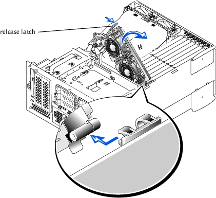
- Rotate the cooling shroud up and lift to clear the back fan assembly and chassis (see
Figure 4-8).
Figure 4-8. Rotating the Cooling Shroud
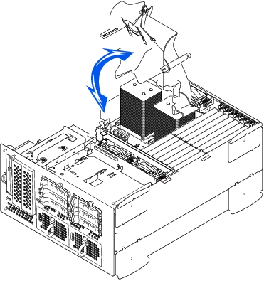
- Lower the cooling shroud into the chassis ensuring that the cooling shroud is aligned
with the rear cooling fan assembly guides.
- Rotate the cooling shroud down ensuring the thumbscrews are aligned with the
connecting posts on the system board (see Figure 4-7).
- Tighten the two thumbscrews securing the cooling shroud to the system board.
- Reconnect the cooling shroud fan cable to the system board.
- Replace the cover (see "Replacing the Cover").
The system includes the following hot-pluggable cooling fans:
- Two fan assemblies containing two individual fans. One assembly is located near the SCSI backplane board. The other fan assembly is attached to the back of the chassis.
- One cooling fan located on the cooling shroud.
|
|
CAUTION: Only trained service technicians are authorized to remove the system cover and access any of the components inside the system. See your System Information Guide for complete information about safety precautions, working inside the computer, and protecting against electrostatic discharge. |
- Open the bezel (see "Removing the Bezel").
- Turn off the system, including any attached peripherals, and disconnect the system
from the electrical outlet.
- Remove the cover (see "Removing the Cover").
- Disconnect the front fan assembly power cable from the front fan connector on the
SCSI backplane board (see Figure 5-4).
- Release the fan assembly by pressing the release lever (see Figure 4-9).
- Swing the fan assembly up and out of the way.
Figure 4-9. Removing and Replacing the Front-Fan Assembly
- Place the fan assembly in the hinge bracket and swing the fan assembly down until the
release lever snaps into place.
- Connect the fan assembly power cable to the front fan connector on the SCSI
backplane board (see Figure 5-4).
- Replace the cover (see "Replacing the Cover").
|
|
CAUTION: Only trained service technicians are authorized to remove the system cover and access any of the components inside the system. See your System Information Guide for complete information about safety precautions, working inside the computer, and protecting against electrostatic discharge. |
- Open the bezel (see "Removing the Bezel").
- Turn off the system, including any attached peripherals, and disconnect the system
from the electrical outlet.
- Remove the cover (see "Removing the Cover").
- Remove the cooling shroud (see "Removing the Cooling Shroud").
- Disconnect the fan assembly power cable from the back fan connector on the system
board (see Figure 5-3).
- Pull on the release latch and lift the fan assembly straight up to clear the chassis (see
Figure 4-10).
Figure 4-10. Removing and Replacing the Back Fan Assembly
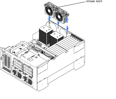
- Align the fan assembly with the fan assembly guide on the back of the chassis, and
push down until the fan assembly is firmly seated and the latch is engaged (see
Figure 4-10).
- Connect the fan assembly power cable to the back fan connector on the system board
(see Figure 4-10).
- Install the cooling shroud (see "Replacing the Cooling Shroud").
- Replace the cover (see "Replacing the Cover").
Each fan assembly contains two fans. The procedure for removing and replacing the four individual fans are the same.
- Remove the system cover (see "Removing the Cover").
 |
NOTICE: The cooling fans are hot-pluggable. To maintain proper cooling while the system is
on, only replace one fan at a time.
|
- Locate the faulty fan and while pressing the fan release lever, lift the fan straight up to
clear the fan assembly (see Figure 4-11).
Figure 4-11. Removing and Replacing Individual Fans
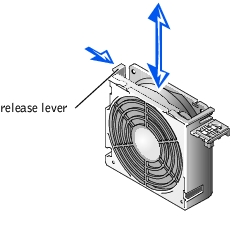
- Lower the fan into the fan assembly until the fan snaps into position.
- Replace the cover (see "Replacing the Cover").
- Remove the cover (see "Removing the Cover").
- Push down on the two release latches and slide the fan out of the bracket on the
cooling shroud (see Figure 4-12).
Figure 4-12. Removing and Replacing the Cooling Shroud Fan
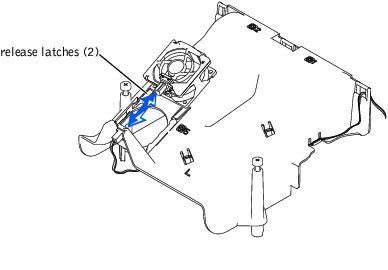
- Slide the fan into the bracket on the cooling shroud until the fan snaps into position
(see Figure 4-12).
- Replace the system cover.
The system includes one or two power supplies. If a single power supply is installed, the system must be shut down and the power cables disconnected from the power receptacle. If there are two power supplies installed, the system is in the redundant mode and the faulty power supply can be removed and replaced with the system is powered on.
|
|
CAUTION: Only trained service technicians are authorized to remove the system cover and access any of the components inside the system. See your System Information Guide for complete information about safety precautions, working inside the computer, and protecting against electrostatic discharge. |
|
NOTICE: The power supplies are hot-pluggable. The system requires one power supply to be
installed for the system to operate normally. The system is in the redundant mode when two
power supplies are installed. Remove and replace only one power supply at a time in a system
that is powered on.
|
- Open the bezel (see "Removing the Bezel").
- If two power supplies are installed, go to step 4.
- If only one power supply is installed, turn off and disconnect the system from the
electrical outlet.
- Grasp the power-supply handle and press down on the release lever while pulling the
power supply straight out to clear the chassis (see Figure 4-13).
Figure 4-13. Removing and Replacing a Power Supply
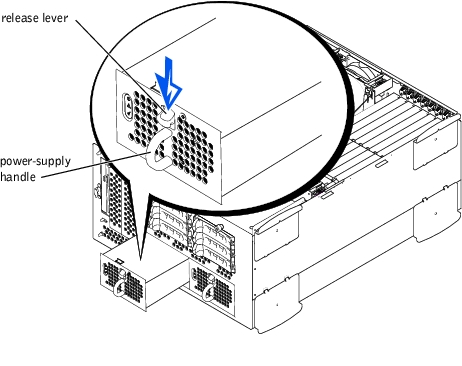
- Slide the power supply into the chassis until it snaps into place (see Figure 4-13).
 |
NOTE: After installing a new power supply, allow several seconds for the system to
recognize the power supply and determine whether it is working properly. The power-on
indicator will turn green to signify that the power supply is functioning properly (see
Figure 3-4).
|
- Close the bezel (see "Replacing the Bezel").
- If you have only one power supply, reconnect the system to its electrical outlet and
turn the system on, including any attached peripherals.
To remove a PDM, perform the following steps.
|
|
CAUTION: Only trained service technicians are authorized to remove the system cover and access any of the components inside the system. See your System Information Guide for complete information about safety precautions, working inside the computer, and protecting against electrostatic discharge. |
- Remove the bezel (see "Removing the Bezel").
- Turn off the system, including any attached peripherals, and disconnect the system
power cable(s) from the electrical outlet(s).
- Release the latch on the power supplies and pull them about an inch away from their
connectors on the PDM.
- Remove the cover (see "Removing the Cover").
- Remove the cooling shroud (see "Removing the Cooling Shroud").
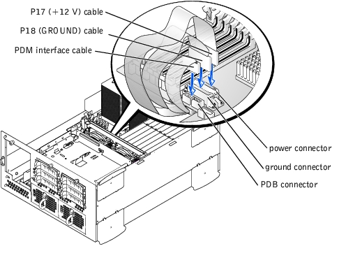
- Disconnect power cable connector P17 from the system board connector POWER
connector (see Figure 4-14).
- Disconnect power cable connector P18 from the system board connector GROUND
connector (see Figure 4-14).
- Disconnect the PDM interface cable from the system board PDB connector (see
Figure 4-14).
Figure 4-14. Disconnecting PDM Cables
- At the back of the system, remove the four screws securing the PDM to the back panel,
as shown in Figure 4-15.
Figure 4-15. Removing the PDM
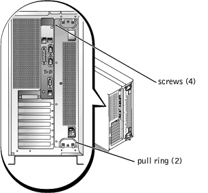
- Carefully use the pull rings to pull the PDM out of its slot, taking care to guide the
connectors you disconnected from the system board down and away from the system
board.
- Slide the replacement PDM into its slot, taking care that its connectors enter the slot
before the module chassis.
- Guide the cables up and insert them into their connectors on the system board:
- Insert the smaller connector into system board connector PDB (see Figure 4-14).
- Insert cable connector P18 into the system board connector GROUND (see
Figure 4-14).
- Insert cable connector P17 into the system board connector POWER (see
Figure 4-14).
- Install the four screws that secure the PDM to the back panel (see Figure 4-15).
The system includes seven expansion slots. The expansion cards are installed on the system board (see Figure 5-3 to identify the expansion slots).
You can install expansion cards of different operating speeds on the same bus; however, the bus will operate at the slowest operating speed of the cards on that bus. For example, if one card on the bus has an operating speed of 66 MHz and the other card has an operating speed of 100 MHz, the bus will only operate at 66 MHz.
To identify expansion slots, see Figure 5-3. Table 4-1 lists the PCI bus and operating speed for each expansion-card slot.
Table 4-1. Expansion Slot Speeds
|
Slot
|
Bus
|
Operating Speed
|
Signaling Level
|
|---|
1 | 0 | 33 MHz | 5 V |
2 | 5 | 33, 66, or 100 MHz | 3.3 V |
3 | 5 | 33, 66, or 100 MHz | 3.3 V |
4 | 4 | 33, 66, or 100 MHz | 3.3 V |
5 | 4 | 33, 66, or 100 MHz | 3.3 V |
6 | 3 | 33, 66, 100, or 133 MHz | 3.3 V |
7 | 2 | 33, 66, 100, or 133 MHz | 3.3 V |
NOTE: If you are using expansion cards of different operating speeds,
you should install the fastest card in slot 7 and the slowest card in slot 1.
NOTE: Do not install Dell™ PowerEdge™ Expandable RAID Controller
(PERC DC/QC) cards in slots 6 or 7.
|
The system's BIOS scans and numbers PCI buses and devices during startup. Expansion slots are scanned according to the host bus ordering, not by the slot numbers. See Table 4-2 for the order in which the expansion slots and embedded PCI devices are scanned.
An additional factor affects the assignment of PCI bus numbers: an expansion card may have its own PCI bridge chip which requires the assignment of a bus number for the card as well as one for the bridge. A particular expansion card may have two PCI bridge chips which would result in three sequential PCI bus numbers all assigned in the same expansion slot.
If you install expansion cards, you may have some difficulty in directly determining the bus number of a controller on a particular expansion card. However, the PCI bus scan order listed in Table 4-2 can help determine the relative numbering of PCI buses within the expansion slots. For example, a PCI controller residing in expansion slot 3 will never have a lower bus number than one in slot 2 because slot 2 precedes slot 3 in the scan order.
Table 4-2. PCI Bus Scan Order
|
Order
|
Device or Slot
|
|---|
1 | Expansion slot 1 |
2 | Embedded remote access components |
3 | Video |
4 | Integrated Gigabit NIC |
5 | Expansion slot 7 |
6 | Expansion slot 6 |
7 | Expansion slot 4 |
8 | Expansion slot 5 |
9 | Expansion slot 4 |
10 | Expansion slot 3 |
11 | Expansion slot 2 |
12 | Optional integrated RAID controller on the system board |
13 | Integrated SCSI controller on the system board |
|
|
CAUTION: Only trained service technicians are authorized to remove the system cover and access any of the components inside the system. See your System Information Guide for complete information about safety precautions, working inside the computer, and protecting against electrostatic discharge. |
- Unpack the expansion card, and prepare it for installation.
For instructions, see the documentation accompanying the card.
- Open the bezel (see "Removing the Bezel").
- Turn off the system, including any attached peripherals, and disconnect the system
from the electrical outlet.
- Remove the cover (see "Removing the Cover").
- Disconnect all expansion-card cables.
- Remove the front fan assembly (see "Removing the Front Fan Assembly").
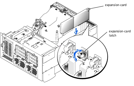
- Open the expansion-card latch (see Figure 4-16) and remove the filler bracket.
- Install the expansion card (see Figure 4-16):
- Position the expansion card so that the card-edge connector aligns with the
expansion-card connector on the system board.
- Insert the card-edge connector firmly into the expansion-card connector until the
card is fully seated.
- When the card is seated in the connector, close the expansion-card latch (see
Figure 4-16).
|
NOTE: SCSI cables connected from an expansion card to the SCSI backplane board
should be routed under the front fan assembly.
|
Figure 4-16. Installing an Expansion Card
- Reconnect all expansion-card cables, including those for the new card.
See the documentation that came with the card for information about its cable connections.
|
NOTE: If the expansion card you are installing is of a different operating speed as the card
already installed on the same PCI bus, all expansion cards on that bus will operate at the
slower speed.
|
- Replace the front fan assembly (see "Removing the Front Fan Assembly").
- Replace the cover (see "Replacing the Cover").
|
|
CAUTION: Only trained service technicians are authorized to remove the system cover and access any of the components inside the system. See your System Information Guide for complete information about safety precautions, working inside the computer, and protecting against electrostatic discharge. |
- Open the bezel (see "Removing the Bezel").
- Turn off the system, including any attached peripherals, and disconnect the system
from the electrical outlet.
- Remove the cover (see "Removing the Cover").
- Disconnect all expansion-card cables.
- Remove the front fan assembly (see "Removing the Front Fan Assembly").
- Release the expansion card:
- Open the expansion-card latch (see Figure 4-16).
- Grasp the expansion card by its top corners, and carefully remove it from the
expansion-card connector.
- If you are removing the card permanently, install a metal filler bracket over the empty
expansion slot opening and close the expansion-card latch.
|
NOTICE: You must install a filler bracket over an empty expansion slot to maintain Federal
Communications Commission (FCC) certification of the system. The brackets also keep dust and
dirt out of the system and aid in proper cooling and airflow inside the system.
|
- Reconnect all expansion-card cables.
- Replace the front fan assembly (see "Replacing the Front Fan Assembly").
- Replace the cover (see "Replacing the Cover").
- Replace the bezel (see "Replacing the Bezel").
To remove the ERA/O card, perform the following steps.
|
|
CAUTION: Only trained service technicians are authorized to remove the system cover and access any of the components inside the system. See your System Information Guide for complete information about safety precautions, working inside the computer, and protecting against electrostatic discharge. |
|
|
CAUTION: Your system has two power supply cables. To reduce the risk of electrical shock, a trained service technician must disconnect both power supply cables before servicing the system. |
|
NOTE: For more information about setting up and using an ERA/O, see the remote
access controller documentation provided on the documentation CD that came with
your system.
|
- Open the bezel (see "Removing the Bezel").
- Turn off the system, including any attached peripherals, and disconnect the system
from the electrical outlet.
- Remove the cover (see "Removing the Cover").
- Remove any full-length expansion-cards that are installed (see "Expansion Cards").
- Remove the front fan assembly (see "Removing the Front Fan Assembly").
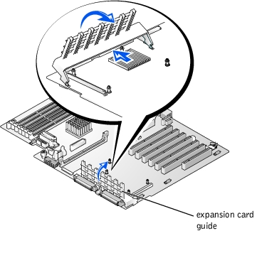
- You must remove the expansion card guide from the system before you remove the
ERA/O card. To remove the expansion card guide, perform the following steps:
- Press the middle of the expansion card guide in the direction of the SCSI
backplane (away from the system board) and carefully rotate the expansion card
guide toward the system board until the card guide unhooks from the system
board (see Figure 4-17).
- Swing the expansion card guide up.
Figure 4-17. Removing the Expansion Card Guide
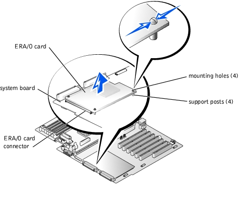
- To remove the ERA/O card from its connector on the system board, unfasten each of
the support posts from the card.
|
NOTICE: Do not attempt to disconnect the ERA/O card from the connector on the system board
until you have unfastened the card from each of the four support posts.
|
- Compress the clasp at the top of the support post while carefully lifting up on the
corner of the card to unseat the post (see Figure 4-18).
- Repeat step a for each support post.
- Lift the ERA/O card straight up and out of the chassis.
- If you are not installing a replacement ERA/O card at this time, disconnect the
network cable from the 10-Mbps server management Ethernet connector on the
system back panel.
Figure 4-18. Removing the ERA/O Card
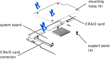
- To install the replacement ERA/O card in the system, perform the following steps:
- Position the ERA/O card so that the card connector is directly over the connector
on the system board and the mounting holes on the card line up with the support
posts on the system board.(see Figure 4-19).
- Press down until the ERA/O-card connector is fully seated in the connector on the
system board and the support posts are secured in the mounting holes on the card.
Figure 4-19. Installing the ERA/O Card
- Reinstall the expansion-card guide:
- Holding the expansion-card guide at a 45-five degree angle, insert the two tabs at
the ends of the expansion-card guide base into the slots on the system board (see
Figure 4-17).
- Rotate the expansion-card guide down until the clip snaps securely onto the
system board.
- Reinstall any expansion cards that you removed (see "Installing an Expansion Card").
|
NOTE: SCSI cables connected from an expansion card to the SCSI backplane board
should be routed under the front fan assembly.
|
- Reinstall the front fan assembly (see "Replacing the Front Fan Assembly").
- Replace the cover (see "Replacing the Cover").
- Replace the bezel (see Replacing the Bezel").
- Connect a network cable to the 10-Mbps server management Ethernet connector on
the system back panel.
- Reconnect the system and peripherals to their electrical outlets, and turn them on.
The CD/diskette drive assembly attaches to the side of the peripheral bay and connects to the IDE controller on the system board through a single ribbon cable.
|
|
CAUTION: Only trained service technicians are authorized to remove the system cover and access any of the components inside the system. See your System Information Guide for complete information about safety precautions, working inside the computer, and protecting against electrostatic discharge. |
- Remove the bezel (see "Removing the Bezel").
- Remove the cover (see "Removing the Cover").
- Turn off the system, including any attached peripherals, and disconnect the system
from its electrical outlet.
- Remove the peripheral bay from the system chassis (see "Removing the Peripheral
Bay").
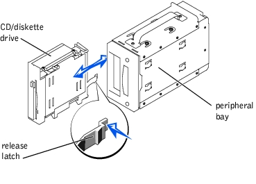
- Lift the CD/diskette drive release latch and slide the CD/diskette drive toward the
front of the peripheral bay (see Figure 4-20).
Figure 4-20. Removing and Installing the CD/Diskette Drive
|
|
CAUTION: Only trained service technicians are authorized to remove the system cover and access any of the components inside the system. See your System Information Guide for complete information about safety precautions, working inside the computer, and protecting against electrostatic discharge. |
- Align the replacement CD/diskette drive assembly with the opening in the side of the
peripheral bay.
- Press the CD/diskette drive assembly firmly into the side of the peripheral bay and
slide the assembly towards the back of the peripheral bay until the release latch snaps
into place (see Figure 4-20).
- Replace the peripheral bay into the system chassis (see "Replacing the Peripheral
Bay").
- Replace the system cover (see "Replacing the Cover").
- Replace the bezel (see "Replacing the Bezel").
- Reconnect your system and peripherals to their electrical outlets, and turn on the
system.
|
|
CAUTION: Only trained service technicians are authorized to remove the system cover and access any of the components inside the system. See your System Information Guide for complete information about safety precautions, working inside the computer, and protecting against electrostatic discharge. |
- Remove the front bezel (see "Removing the Bezel").
- Remove the system cover (see "Removing the Cover").
- Disconnect the chassis intrusion switch cable connector on the system board.
- Grasp and slide the switch toward the center of the front panel until it becomes free of
its slot (see Figure 4-21).
Figure 4-21. Chassis Intrusion Switch Replacement

Although SCSI devices are installed in essentially the same way as other devices, their configuration requirements are different. To install and configure an external SCSI device, follow the guidelines in the following subsections.
SCSI interface connectors are keyed for correct insertion. Keying ensures that the pin-1 wire in the cable connects to pin 1 in the connectors on both ends. When you disconnect an interface cable, take care to grasp the cable connector, rather than the cable itself, to avoid stress on the cable.
Each device attached to a SCSI host adapter must have a unique SCSI ID number from 0 to 15.
A SCSI tape drive is configured by default as SCSI ID 6.
|
NOTE: There is no requirement that SCSI ID numbers be assigned sequentially or that
devices be attached to the cable in order by ID number.
|
SCSI logic requires that termination be enabled for the two devices at opposite ends of the SCSI chain and disabled for all devices in between. For internal SCSI devices, termination is configured automatically. For external SCSI devices, you should disable termination on all devices and use terminated cables. See the documentation provided with any optional SCSI device you purchase for information on disabling termination.
This subsection describes how to configure and install an external SCSI tape drive.
|
|
CAUTION: Only trained service technicians are authorized to remove the system cover and access any of the components inside the system. See your System Information Guide for complete information about safety precautions, working inside the computer, and protecting against electrostatic discharge. |
- Turn off the system, including any attached peripherals, and disconnect the system
from the electrical outlet.
- Prepare the tape drive for installation.
Ground yourself by touching an unpainted metal surface on the back of the system, unpack the drive (and controller card, if applicable), and compare the jumper and switch settings with those in the drive documentation. Change any settings necessary for your system's configuration.
- Connect the tape drive's interface cable to the external SCSI connector on the
controller card.
- Reconnect the system to its electrical outlet and turn the system on, including any
attached peripherals.
- Perform a tape backup and verification test with the drive as instructed in the software
documentation that came with the drive.
This subsection describes how to install and configure SCSI hard drives in the system's internal hard-drive bays.
Before attempting to remove or install a drive while the system is running, see the documentation for the RAID controller card ensure that the system is configured correctly to support hot-pluggable drive removal and insertion.
SCSI hard drives are supplied in special drive carriers that fit in the hard-drive bays.
|
NOTE: You should only use drives that have been tested and approved by the system
manufacturer for use with the SCSI backplane board.
|
You may need to use different programs than those provided with the operating system to partition and format hard drives. See "Installing and Configuring SCSI Drivers" in the User's Guide for information and instructions.
|
NOTICE: Do not turn off or reboot your system while the drive is being formatted. Doing so can
cause a drive failure.
|
When you format a high-capacity hard drive, allow enough time for the formatting to be completed. Long format times for these drives are normal. For example, an exceptionally large drive can take over an hour to format.
The hard-drive bays provide space for up to six 1-inch SCSI hard drives. The hard drives connect to a controller on the system board or a RAID controller card through the SCSI backplane board.
The system provides several options for hard drive configurations:
|
NOTICE: The daughter card is required only for the 2 x 3 (2 channels with 3 drives each)
configuration.
|
- 1 x 6 configuration, without the SCSI backplane daughter card installed
- 2 x 3 split configuration, with the SCSI backplane daughter card installed
- 2 x 3 + 1 x 2 split configuration, with the SCSI backplane daughter card installed and two hard drives installed in the peripheral bay
- 1 x 6 + 1 x 2 split configuration, without the SCSI backplane daughter card installed and two hard drives installed in the peripheral bay
- SCSI controller:
- Cabling:
- If the onboard SCSI controller or the optional integrated RAID controller is used, SCSI cables connect from the system board to the 1 x 6 backplane for both SCSI channels.
- If a RAID controller card is installed, the onboard SCSI cables are removed and longer cables are installed from the controller card to SCSI A and/or SCSI B backplane board connector(s).
- If a cable is connected to the SCSI B backplane board connector, the SCSI backplane daughter card must be installed to activate the 2 x 3 split configuration. Otherwise, the system will display an error message.
See Figure 5-4 to locate the connectors on the SCSI backplane board.
|
NOTICE: Not all operating systems support hot-plug drive installation. See the documentation
supplied with your operating system.
|
- Remove the bezel (see "Removing the Bezel").
- Take the hard drive offline and wait until the hard-drive indicator codes on the drive
carrier signal that the drive may be removed safely (see Table 3-6).
If the drive has been online, the drive status indicator will blink green twice per second as the drive is powered down. When all indicators are off, the drive is ready for removal.
See your operating system documentation for more information on taking the hard drive offline.
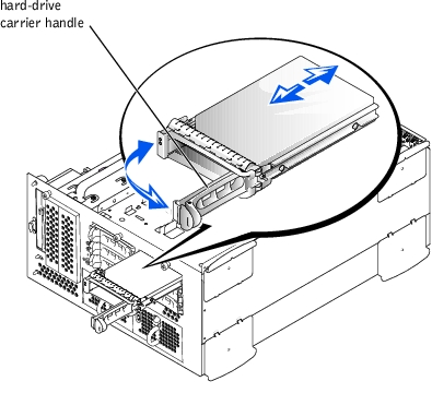
- Open the hard-drive carrier handle to release the drive (see Figure 4-22).
- Slide the hard drive out until it is free of the drive bay (see Figure 4-22).
If you are permanently removing the hard drive, install a blank insert.
Figure 4-22. Removing and Installing a Hard Drive
- Replace the bezel (see "Replacing the Bezel").
- If your replacement hard drive does not have a carrier, remove the faulty drive from its
carrier (see "Removing a Hard Drive From Its Carrier").
|
NOTICE: When installing a hard drive, ensure that the adjacent drives are fully installed.
Inserting a hard-drive carrier and attempting to lock its handle next to a partially installed
carrier can damage the partially installed carrier's shield spring and make it unusable.
|
|
NOTICE: Not all operating systems support hot-plug drive installation. See the documentation
supplied with your operating system.
|
- Remove the bezel (see "Removing the Bezel").
- If your replacement hard drive does not have a carrier, install the new drive on a carrier
(see "Installing a Hard Drive on a Carrier").
- Open the hard-drive carrier handle (see Figure 4-22).
|
NOTICE: Do not insert a hard-drive carrier and attempt to lock its handle next to a partially
installed carrier. Doing so can damage the partially installed carrier's shield spring and make it
unusable. Ensure that the adjacent drive carrier is fully installed.
|
- Insert the hard-drive carrier into the drive bay (see Figure 4-22).
- Close the hard-drive carrier handle to lock it in place.
- Replace the bezel (see "Replacing the Bezel").
- Install any required SCSI device drivers (see "Installing and Configuring SCSI Drivers"
in the User's Guide for information).
- If the hard drive is new, run the SCSI controllers test in system diagnostics.
|
|
CAUTION: See your System Information Guide for complete information about safety precautions, working inside the computer, and protecting against electrostatic discharge. |
- Remove the hard drive from the system (see "Removing a Hard Drive").
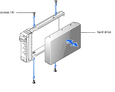
- Remove the four screws that secure the drive to the carrier (see Figure 4-23).
- Remove the hard drive from the carrier.
Figure 4-23. Removing a Hard Drive From Its Carrier
|
|
CAUTION: See your System Information Guide for complete information about safety precautions, working inside the computer, and protecting against electrostatic discharge. |
- Insert the replacement hard drive into the carrier (see Figure 4-23).
- Install the four screws that secure the drive to the carrier.
- Install the hard drive in the system (see "Installing a Hard Drive").
To activate the integrated RAID controller, you must install three components, the RAID controller memory module, hardware key, and battery.
|
|
CAUTION: Only trained service technicians are authorized to remove the system cover and access any of the components inside the system. See your System Information Guide for complete information about safety precautions, working inside the computer, and protecting against electrostatic discharge. |
|
|
CAUTION: Replace the battery only with the same or equivalent type recommended by the manufacturer. Discard used batteries according to the manufacturer's instructions. See the System Information Guide for additional information. |
|
NOTICE: To avoid possible data loss, back up all data on the hard drives before changing the
mode of operation of the integrated SCSI controller from SCSI to RAID.
|
- Turn off the system, including any attached peripherals, and disconnect the system
from the electrical outlet.
- Remove the cover (see "Removing the Cover").
- Push the ejectors on the RAID memory module connector down and outward to allow
the memory module to be inserted into the connector (see Figure 4-24).
See Figure 5-3 to locate the RAID memory module connector on the system board.
- Align the memory module's edge connector with the alignment keys, and insert the
memory module into the connector (see Figure 4-24).
The memory module connector has two alignment keys that allow the memory module to be installed into the connector in only one way.
|
NOTE: The RAID controller memory module must be an unbuffered memory module, rated
to run at 100 MHz or faster. Do not substitute registered memory modules such as those
used for system memory.
|
- Press on the memory module with your thumbs while pulling up on the ejectors with
your index fingers to lock the memory module into the connector.
Figure 4-24. Installing the RAID Controller Memory Module
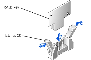
- Push the ejectors on the RAID hardware key connector down and outward to allow the
key to be inserted into the connector (see Figure 4-25).
- Insert the RAID hardware key into its connector on the system board and secure the
key with the latches on each end of the connector (see Figure 4-25).
See Figure 5-3 to locate the RAID hardware key on the system board.
- Press on the hardware key with your thumbs while pulling up on the ejectors with your
index fingers to lock the hardware key into the connector.
Figure 4-25. Installing the RAID Hardware Key
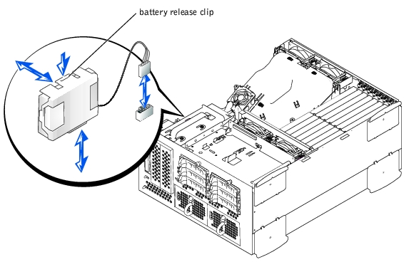
- Connect the battery cable to the RAID battery cable connector on the system board.
See Figure 5-3 to locate the RAID battery cable connector on the system board.
- Hook the retention tab on the bottom of the battery into the slot in the chassis side
wall, and then snap the battery release clip into place (see Figure 4-26).
Figure 4-26. Removing and Installing the RAID Battery
- Replace the cover (see "Replacing the Cover").
- Reconnect the system to its electrical outlet and turn the system on, including any
attached peripherals.
- Enter the System Setup program and verify that the setting for the SCSI controller has
changed to reflect the presence of the RAID hardware (see "Using the System Setup
Program").
- Install the RAID software.
See the RAID controller documentation for more information.
Follow these general guidelines when installing a RAID controller card. For specific instructions, see the documentation supplied with the RAID controller card.
|
|
CAUTION: Only trained service technicians are authorized to remove the system cover and access any of the components inside the system. See your System Information Guide for complete information about safety precautions, working inside the computer, and protecting against electrostatic discharge. |
|
NOTICE: To avoid possible data loss, back up all data on the hard drives before changing the
mode of operation of the integrated SCSI controller from SCSI to RAID.
|
- Unpack the RAID controller card, and prepare it for installation.
For instructions, see the documentation accompanying the card.
- Turn off the system, including any attached peripherals, and disconnect the system
from the electrical outlet.
- Remove the cover (see "Removing the Cover").
- Install the RAID controller card (see "Installing an Expansion Card").
- Connect SCSI interface cables supplied with the card to the SCSIA and/or SCSIB
connectors on the SCSI backplane board.
|
NOTE: Cables can be connected from the RAID controller card to SCSIA and/or SCSIB
backplane board connector(s). A backplane board connector that is not attached to the
RAID controller card will use the integrated SCSI controller or optional integrated RAID
controller.
|
To identify the connector on the RAID controller card, see documentation for the card. See Figure 5-4 to locate the SCSI controller connectors on the SCSI backplane board.
Route the SCSI cables over the SCSI backplane board to the RAID controller card.
- Connect the external SCSI devices to the card's external connector on the system's
back panel.
If you are attaching multiple external SCSI devices, daisy-chain the devices to each other using the cables shipped with each device.
- Replace the cover (see "Removing the Cover").
- Reconnect the system to its electrical outlet and turn the system on, including any
attached peripherals.
- Install any required SCSI device drivers (see "Installing and Configuring SCSI Drivers"
in the User's Guide).
- Test the SCSI devices.
Test a SCSI hard drive by running the SCSI Controllers test in the system diagnostics.
To operate the SCSI backplane in a 2 x 3 split backplane configuration, you must install a daughter card.
|
|
CAUTION: Only trained service technicians are authorized to remove the system cover and access any of the components inside the system. See your System Information Guide for complete information about safety precautions, working inside the computer, and protecting against electrostatic discharge. |
|
NOTICE: To avoid possible data loss, back up all data on the hard drives before changing the
SCSI configuration.
|
- Unpack the SCSI backplane board daughter card kit.
- Turn off the system, including any attached peripherals, and disconnect the system
from the electrical outlet.
- Remove the cover (see "Removing the Cover").
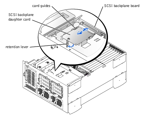
- The daughter card fits between the sides of the card guide above the drive bay. To
install the daughter card in the card guide, performing the following steps:
- Hold the daughter card by its edges with the component side facing up and the
card connector facing the SCSI backplane board (see Figure 4-27).
- Ensure that the retention lever is in the open position.
- Position the card in the drive bay so that the notches on the left and right edges of
the card are aligned with the tabs on the card guide above the drive bay.
- Lower the card into the card guide.
- Close the retention lever to slide the daughter card into the SCSI backplane
connector and lock the card into place (see Figure 4-27).
Figure 4-27. Installing a SCSI Backplane Daughter Card
- Reconfigure the SCSI cable connections to the SCSI backplane as necessary to
operate the backplane as a 2 x 3 split backplane:
An integrated RAID controller card is installed by default; no cables are required to use the integrated RAID controller in either the 1 x 5 or 2 x 3 split configuration. See Figure 5-4 to locate the connectors on the SCSI backplane board.
- Replace the cover (see "Removing the Cover").
- Reconnect your system and peripherals to their electrical outlets, and turn on the
system.
|
|
CAUTION: Only trained service technicians are authorized to remove the system cover and access any of the components inside the system. See your System Information Guide for complete information about safety precautions, working inside the computer, and protecting against electrostatic discharge. |
|
NOTICE: To avoid possible data loss, back up all data on the hard drives before changing the
SCSI configuration.
|
- Turn off the system, including any attached peripherals, and disconnect the system
from the electrical outlet.
- Pull the retention lever to slide the daughter card away from the SCSI backplane
connector (see Figure 4-27).
- Lift the card up and away from the tabs on the card guide above the drive bay (see
Figure 4-27).
The system contains up to six 1-inch SCSI hard drives that connect to a controller on the system board or a RAID controller card through the SCSI backplane board.
|
|
CAUTION: Only trained service technicians are authorized to remove the system cover and access any of the components inside the system. See your System Information Guide for complete information about safety precautions, working inside the computer, and protecting against electrostatic discharge. |
- Turn off the system, including any attached peripherals, and disconnect the system
from the electrical outlet.
- Remove the cover (see "Removing the Cover").
- Remove the SCSI backplane daughter card if it is installed (see "Removing the SCSI
Backplane Daughter Card").
- Remove all hard drives (see "Removing a Hard Drive").
- Disconnect the front fan assembly power cable from its P1 connector on the front of
the SCSI backplane board.
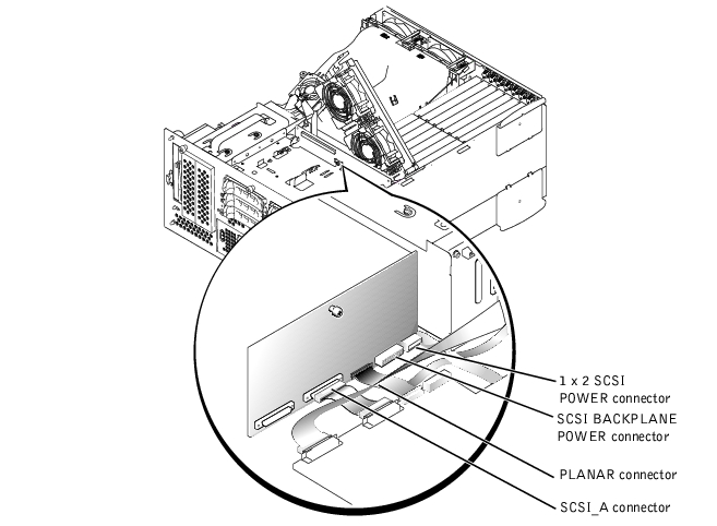
- Disconnect the SCSI_A connector from the SCSI_A connector on the back of the
SCSI backplane board (see Figure 4-28).
- Pull the locking bar to the unlock position to remove the flat cable connector
(BKPLN) from the PLANAR CONNECTOR on the back of the SCSI backplane board
(see Figure 4-28).
- Disconnect the 14-conductor power cable from the SCSI BACKPLANE POWER
connector on the back of the SCSI backplane board (see Figure 4-28).
- Disconnect the 4-conductor power cable from the 1 x 2 SCSI POWER connector on
the back of the SCSI backplane board (see Figure 4-28).
- Loosen the thumbscrew that secures the SCSI backplane board in the system (see
Figure 4-28).
- Slide the backplane board up about 0.5 inch.
- Pull the backplane board off of its grounding tabs.
- Lift the backplane board out of the system (see Figure 4-28).
Figure 4-28. Removing and Replacing the SCSI Backplane Board
|
|
CAUTION: Only trained service technicians are authorized to remove the system cover and access any of the components inside the system. See your System Information Guide for complete information about safety precautions, working inside the computer, and protecting against electrostatic discharge. |
- Lower the backplane board into the system.
|
NOTICE: To avoid damage to the system, align the bottom of the backplane board in the
board's mounting grooves before rotating the top of the board onto the grounding tabs (see
Figure 4-28).
|
- Align the backplane board onto the board's grounding tabs.
- Slide the backplane board down about 0.5 inch.
- Tighten the thumbscrew on the backplane board.
- Install all SCSI hard drives (see "Installing a Hard Drive").
- Install the SCSI backplane daughter card (see "Installing the SCSI Backplane
Daughter Card").
- Insert the SCSI_A cable into the SCSI_A connector on the back of the SCSI
backplane board (see Figure 4-28).
- Pull the locking bar to the unlock position to insert the flat cable connector (BKPLN)
into the PLANAR CONNECTOR on the back of the SCSI backplane board; next,
push the locking bar to lock the flat cable into the connector (see Figure 4-28).
- Insert the 14-conductor power cable into the SCSI BACKPLANE POWER connector
on the back of the SCSI backplane board (see Figure 4-28).
- Insert the 4-conductor power cable into the 1 x 2 POWER connector on the back of
the SCSI backplane board (see Figure 4-28).
- Insert the front fan cable into the P1 connector on the front of the SCSI backplane
board.
- Replace the cover (see "Replacing the Cover").
- Reconnect your system and peripherals to their electrical outlets, and turn on the
system.
The six memory module connectors on the system board can accommodate a minimum of 256 MB of registered memory modules. The memory module connectors are arranged in pairs which consist of three banks
(bank 1, bank 2, and bank 3).
The system is upgradable by installing combinations of 128-, 256-, 512-MB, or 1-GB registered DDR SDRAM modules. You can purchase memory upgrade kits as needed.
|
NOTICE: The memory modules must be PC-2100 compliant.
|
Starting with the connector nearest the side of the chassis, the memory module connectors are labeled
"DIMM_1A" through "DIMM_3B" (see Figure 4-29). When you install memory modules, follow these guidelines:
- You must install memory modules in matched pairs.
- Install a pair of memory modules in connector DIMM_1A and DIMM_1B before installing a second pair in connectors
DIMM_2A and DIMM_2B, and so on.
Figure 4-29. Memory Module Connectors
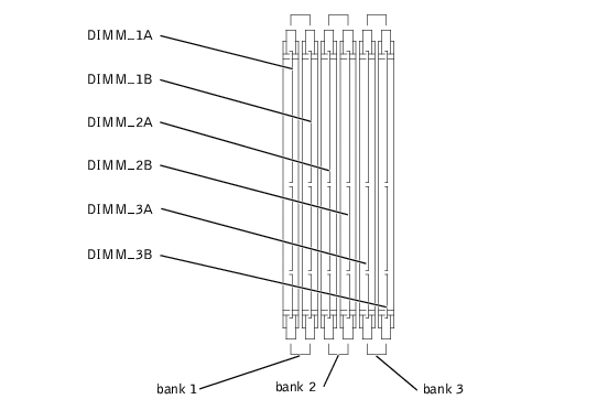
Table 4-3 lists several sample memory configurations based on these guidelines.
Table 4-3. Sample Memory Module Configurations
|
Total Desired
Memory
|
Bank 1
|
Bank 2
|
Bank 3
|
|---|
|
A
|
B
|
C
|
D
|
E
|
F
|
|---|
256 MB | 128 MB | 128 MB | None | None | None | None |
512 MB | 256 MB | 256 MB | None | None | None | None |
1 GB | 512 MB | 512 MB | None | None | None | None |
2 GB | 512 MB | 512 MB | 512 MB | 512 MB | None | None |
3 GB | 512 MB | 512 MB | 512 MB | 512 MB | 512 MB | 512 MB |
6 GB | 1 GB | 1 GB | 1 GB | 1 GB | 1 GB | 1 GB |
|
|
CAUTION: Before you perform this procedure, you must turn off the system and disconnect it from its power source. For more information, see the safety instructions in your System Information Guide. |
|
|
CAUTION: Only trained service technicians are authorized to remove the system cover and access any of the components inside the system. See your System Information Guide for complete information about safety precautions, working inside the computer, and protecting against electrostatic discharge. |
- Open the bezel (see "Removing the Bezel").
- Turn off the system, including any attached peripherals, and disconnect the system
from the electrical outlet.
- Remove the cover (see "Removing the Cover").
- Remove the cooling shroud (see "Removing the Cooling Shroud").
- Install or replace the memory module pairs as necessary to reach the desired memory
total (see "Installing Memory Modules" and "Removing Memory Modules").
See Figure 4-29 to locate the memory module connectors.
- Replace the cooling shroud (see "Replacing the Cooling Shroud").
- Replace the cover (see "Replacing the Cover").
- Reconnect the system to its electrical outlet and turn the system on, including any
attached peripherals.
After the system completes the POST routine, it runs a memory test.
The system detects that the new memory does not match the system configuration information, which is stored in NVRAM. The monitor displays an error message that ends with the following words:
Press <F1> to continue; <F2> to enter System Setup
- Press <F2> to enter the System Setup program, and check the System Memory
setting.
The system should have already changed the value in the System Memory setting to reflect the newly installed memory.
- If the System Memory value is incorrect, one or more of the memory modules may not
be installed properly. Repeat step 1 through step 8, ensuring that the memory modules
are firmly seated in their connectors.
- Run the system memory test in system diagnostics.
|
|
CAUTION: Only trained service technicians are authorized to remove the system cover and access any of the components inside the system. See your System Information Guide for complete information about safety precautions, working inside the computer, and protecting against electrostatic discharge. |
- Open the bezel (see "Removing the Bezel").
- Turn off the system, including any attached peripherals, and disconnect the system
from the electrical outlet.
- Remove the cover (see "Removing the Cover").
- Remove the cooling shroud (see "Removing the Cooling Shroud").
- Locate the memory module connectors in which you will install a memory module
(see Figure 4-29).
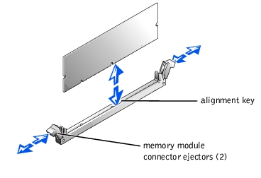
- Press down and outward on the memory module connector ejectors, as shown in
Figure 4-30, to allow the memory module to be inserted into the connector.
Figure 4-30. Removing and Installing a Memory Module
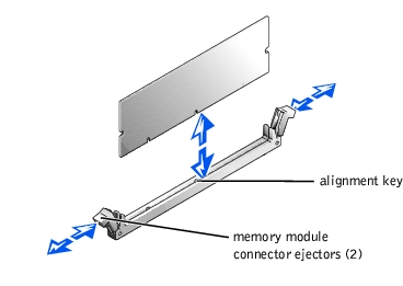
- Align the memory module's edge connector with the alignment key, and insert the
memory module in the connector (see Figure 4-30).
The memory module connector has an alignment key that allows the memory module to be installed in the connector in only one way.
- Press down on the memory module with your thumbs while pulling up on the ejectors
with your index fingers to lock the memory module into the connector (see
Figure 4-30).
When the memory module is properly seated in the connector, the memory module connector ejectors should align with the ejectors on the other connectors with memory modules installed.
- Repeat step 5 through step 8 of this procedure to install the remaining memory
modules.
- Perform step 6 through step 11 of the procedure in "Performing a Memory Upgrade."
|
|
CAUTION: Only trained service technicians are authorized to remove the system cover and access any of the components inside the system. See your System Information Guide for complete information about safety precautions, working inside the computer, and protecting against electrostatic discharge. |
- Open the bezel (see "Removing the Bezel").
- Turn off the system, including any attached peripherals, and disconnect the system
from the electrical outlet.
- Remove the cover (see "Removing the Cover").
- Remove the cooling shroud (see "Removing the Cooling Shroud").
- Locate the memory module connectors from which you will remove memory modules
(see Figure 4-29).
- Press down and outward on the memory module connector ejectors until the memory
module pops out of the connector (see Figure 4-30).
- Repeatstep 4 through step 6 of this procedure to remove any other memory modules.
- Perform step 6 through step 11 of the procedure in "Performing a Memory Upgrade."
To take advantage of future options in speed and functionality, you can add a second microprocessor or replace either the primary or secondary microprocessor.
|
NOTE: The second microprocessor must be of the same type as the first. If the two
microprocessors are different speeds, both will operate at the speed of the slower
microprocessor.
|
Each microprocessor and its associated cache memory are contained in a PGA package that is installed in a ZIF socket on the system board. A second ZIF socket accommodates a secondary microprocessor.
|
NOTE: In a single microprocessor system, the microprocessor must be installed in the
PROC 1 socket.
|
- A microprocessor
- A heat sink
- Two securing clips
- A VRM, if adding a second microprocessor
|
|
CAUTION: Before you perform this procedure, you must turn off the system and disconnect it from its power source. For more information, see the safety instructions in your System Information Guide. |
|
|
CAUTION: Only trained service technicians are authorized to remove the system cover and access any of the components inside the system. See your System Information Guide for complete information about safety precautions, working inside the computer, and protecting against electrostatic discharge. |
- Open the bezel (see "Removing the Bezel").
- Turn off the system, including any attached peripherals, and disconnect the system
from the electrical outlet.
- Remove the cover (see "Removing the Cover").
- Remove the cooling shroud (see "Removing the Cooling Shroud").
- Remove the back fan assembly (see "Removing the Back Fan Assembly"). If you are
installing a second microprocessor, go to step 9.
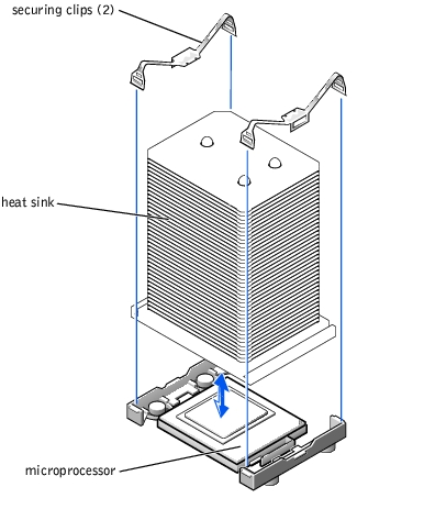
- Remove the microprocessor heat sink:
- Press down on the heat-sink securing clips to release the clips from the retaining
tabs on the ZIF socket (see Figure 4-31).
- Remove the heat-sink securing clips.
|
|
CAUTION: The microprocessor and heat sink can become extremely hot. Be sure the microprocessor has had sufficient time to cool before handling. |
|
NOTICE: Never remove the heat sink from a microprocessor unless you intend to remove the
microprocessor. The heat sink is required to maintain proper thermal conditions.
|
- Lift the heat sink out of the chassis and place it on its side.
Figure 4-31. Removing and Replacing a Heat Sink
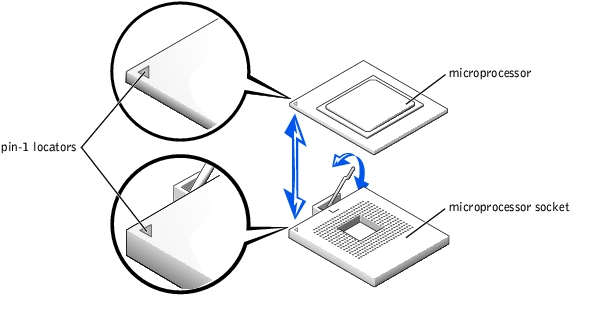
- Pull the socket release lever straight up until the microprocessor is released (see
Figure 4-32).
- Lift the microprocessor out of the socket and leave the release lever up so that the
socket is ready for the new microprocessor.
|
NOTICE: Be careful not to bend any of the pins when removing the microprocessor. Bending
the pins can permanently damage the microprocessor.
|
Figure 4-32. Removing and Replacing a Microprocessor
- Unpack the new microprocessor.
If any of the pins on the microprocessor appear bent, contact the system manufacturer.
- Ensure that the release lever on the microprocessor socket is in the upright position.
- Align pin 1 on the microprocessor (see Figure 4-32) with pin 1 on the microprocessor
socket.
|
NOTE: Force is not needed to install the microprocessor in the socket. When the
microprocessor is aligned correctly, it should drop into the socket.
|
- Install the microprocessor in the socket (see Figure 4-32).
|
NOTICE: Positioning the microprocessor incorrectly can permanently damage the
microprocessor and the system when you turn on the system. When placing the microprocessor
in the socket, be sure that all of the pins on the microprocessor go into the corresponding holes.
Be careful not to bend the pins.
|
- When the microprocessor is fully seated in the socket, rotate the socket release lever
back down until it snaps into place, securing the microprocessor.
- Place the new heat sink on top of the microprocessor (see Figure 4-31).
- Orient the securing clips as shown in Figure 4-31.
- Hook the end of the clips without the latch to the tab on the edge of the socket.
- Push down and pivot the securing clip latch until the hole on the clip latches onto the
ZIF socket tab.
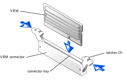
- If you are adding a second microprocessor, you must install a VRM in the VRM 2
connector, pushing down firmly to make sure that the latches engage (see
Figure 4-33).
Figure 4-33. Installing the VRM
- Replace the back fan assembly (see "Replacing the Back Fan Assembly").
- Replace the cooling shroud (see "Replacing the Cooling Shroud").
- Replace the cover (see "Replacing the Cover").
- Reconnect the system to its electrical outlet and turn the system on, including any
attached peripherals.
- Enter the System Setup program, and ensure that the microprocessor options match
the new system configuration (see "Using the System Setup Program").
As the system boots, it detects the presence of the new microprocessor and automatically changes the system configuration information in the System Setup program. If you installed a second microprocessor, a message similar to the following appears:
Two 2.2 GHZ Processors, Processor Bus: 400 MHz, L2 cache
512 KB Advanced
If only one microprocessor is installed, a message similar to the following appears:
One 2.2 GHz Processor, Processor Bus: 400 MHz, L2 cache
512 KB Advanced
- Confirm that the top line of the system data area in the System Setup program
correctly identifies the installed microprocessor(s) (see "Using the System Setup
Program").
- Exit the System Setup program.
- Run the system diagnostics to verify that the new microprocessor is operating
correctly.
See "Running the System Diagnostics" for information on running the diagnostics and troubleshooting any problems that may occur.
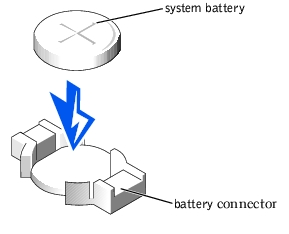
The system battery is a 3.0-volt (V), coin-cell battery.
|
|
CAUTION: Before you perform this procedure, you must turn off the system and disconnect it from its power source. For more information, see the safety instructions in your System Information Guide. |
|
|
CAUTION: There is a danger of a new battery exploding if it is incorrectly installed. Replace the battery only with the same or equivalent type recommended by the manufacturer. Discard used batteries according to the manufacturer's instructions. See the System Information Guide for additional information. |
|
|
CAUTION: Only trained service technicians are authorized to remove the system cover and access any of the components inside the system. See your System Information Guide for complete information about safety precautions, working inside the computer, and protecting against electrostatic discharge. |
- Open the bezel (see "Removing the Bezel").
- Turn off the system, including any attached peripherals, and disconnect the system
from the electrical outlet.
- Remove the cover (see "Removing the Cover").
- Remove any expansion cards that are installed above the system battery (see
"Expansion Cards").
- Remove the system battery (see Figure 4-34).
See Figure 4-34 to locate the system battery on the system board.
You can pry the system battery out of its connector with your fingers or with a blunt, nonconductive object such as a plastic screwdriver.
- Install the new system battery with the side labeled "+" facing up (see Figure 4-34).
Figure 4-34. Removing and Installing the System Battery
- Replace any expansion cards that were removed in step 3 (see "Expansion Cards").
- Replace the cover (see "Removing the Cover").
- Reconnect the system to its electrical outlet and turn the system on, including any
attached peripherals.
- Enter the System Setup program to confirm that the battery is operating properly (see
"Using the System Setup Program").
- Enter the correct time and date in the System Setup program's Time and Date fields.
- Exit the System Setup program.
- To test the newly installed battery, turn off the system and disconnect it from the
electrical outlet for at least an hour.
- After an hour, reconnect the system to its electrical outlet and turn it on.
- Enter the System Setup program and if the time and date are still incorrect, replace
the system board (see "System Board").
|
|
CAUTION: Only trained service technicians are authorized to remove the system cover and access any of the components inside the system. See your System Information Guide for complete information about safety precautions, working inside the computer, and protecting against electrostatic discharge. |
- Turn off the system, including any attached peripherals, and disconnect the system
from the electrical outlet.
- Remove the cover (see "Removing the Cover").
- Remove the cooling shroud (see "Removing the Cooling Shroud").
- Remove the front cooling fans (see "Removing the Front Fan Assembly").
- Remove the back cooling fans (see "Removing the Back Fan Assembly").
- Remove the expansion-cards (see "Removing an Expansion Card").
- Remove the ERA/O card (see "Removing the ERA/O Card").
- Remove the memory modules (see "Removing Memory Modules").
- Remove the memory module, hardware key, and battery for the integrated RAID
controller (if those components are installed) (see "Activating the Integrated RAID
Controller").
- Remove the microprocessors and VRMs (see "Removing and Replacing a
Microprocessor").
- Remove the system battery (see "Removing and Replacing the System Battery").
- Remove the IDE cable for the CD/diskette drive (see "Removing the CD/Diskette
Drive").
- Remove all other cables attached to the system board (including the intrusion alarm
cable, the control panel cable, and the three cables from the power distribution
module).
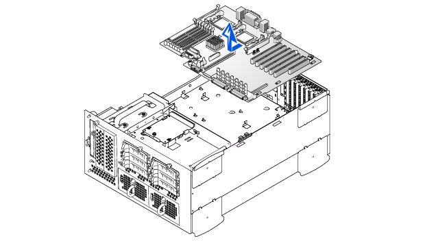
- Remove the system board (see Figure 4-35):
- Loosen the system board's thumbscrew and slide the system board forward about
0.5 inch.
- Lift the system board off its grounding tabs in the system.
Figure 4-35. Removing the System Board
|
|
CAUTION: Only trained service technicians are authorized to remove the system cover and access any of the components inside the system. See your System Information Guide for complete information about safety precautions, working inside the computer, and protecting against electrostatic discharge. |
- Lower the system board onto its grounding tabs and slide the system board back until
the board's thumbscrew can be tightened to secure the system board into place (see
Figure 4-35).
- Replace the system battery (see "Removing and Replacing the System Battery").
- Replace the microprocessors and VRMs (see "Removing and Replacing a
Microprocessor").
- If necessary, replace the memory module, hardware key, and battery for the integrated
RAID controller (see "Activating the Integrated RAID Controller").
- Install the memory modules (see "Installing Memory Modules").
- Replace the expansion-cards (see "Expansion Cards").
- Replace the ERA/O card (see "Installing a Replacement ERA/O Card").
- Replacing the cooling shroud (see "Replacing the Cooling Shroud").
- Replace the cooling fans (see "System Fans").
- Replace the power supplies (see "Replacing a Power Supply").
- Replace the cover (see "Replacing the Cover").
- Replace all other cables removed when the system board was removed (intrusion alarm
cable, control panel cable, IDE cable for the CD/diskette drive, and the power and
interface cables from the power distribution module).
- Reconnect the system to its electrical outlet(s) and turn the system on, including any
attached peripherals.
Back to Contents Page