Back to Contents Page
Installing System Components
Dell™ PowerEdge™ 2900 Systems Hardware Owner's Manual
This section describes how to install the following system components:
- Hot-plug hard drives
- Power supplies
- Cooling fans
- Expansion cards
- Tape, optical, and diskette drives
- System battery
- System memory
- RAC card
- Microprocessors
- SAS backplane board
- SAS controller daughter card
- Control panel assembly
- System board
- Power distribution board
Recommended Tools
You may need the following items to perform the procedures in this section:
- Keys to the system keylocks
- #2 Phillips screwdriver
- T10 Torx driver
- Wrist grounding strap
Opening and Closing the System
The system is enclosed by an optional bezel and cover. To upgrade or troubleshoot the system, remove the bezel and cover to access the drives and internal system components.
Removing the Bezel
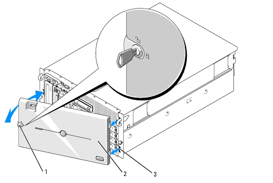
Removing the Rack Bezel
- Unlock the keylock at the left end of the bezel. See Figure 3-1.
- While grasping the bezel, press the release latch on the left edge of the bezel, adjacent to the keylock.
- Rotate the left end of the bezel away from the front panel.
- Unhook the right end of the bezel and pull the bezel away from the system. See Figure 3-1.
Figure 3-1. Installing and Removing the Optional Bezel (Rack)
|
1
|
key lock
|
2
|
bezel (rack)
|
3
|
bezel slot (2)
|
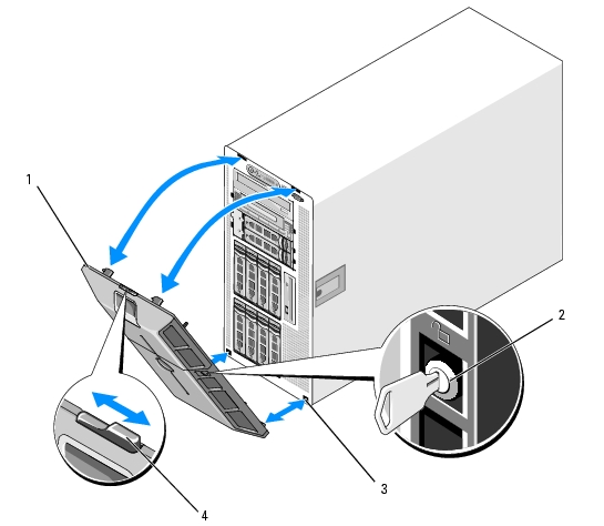
Removing the Tower Bezel
- Unlock the keylock at the right side of the bezel. See Figure 3-2.
- While grasping the bezel, push the release latch on top of bezel to the left.
- Rotate the top of the bezel away from the front panel.
- Unhook the bottom of the bezel and pull the bezel away from the system. See Figure 3-2.
Figure 3-2. Installing and Removing the Optional Bezel (Tower)
|
1
|
bezel
|
2
|
keylock
|
3
|
bezel slot (2)
|
|
4
|
bezel latch
|
|
|
|
|
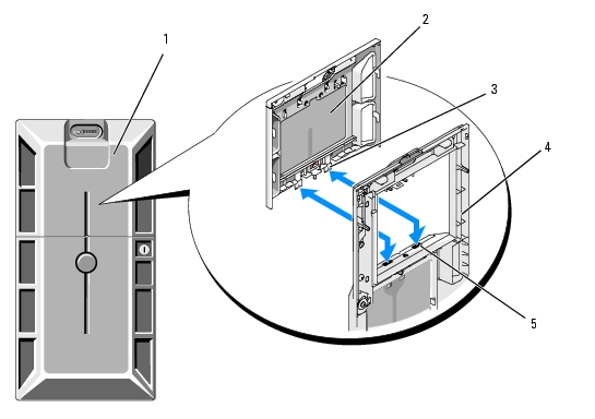
Removing the Peripheral Bay Panel (Tower Only)

|
NOTE: The peripheral bay panel can be removed only from inside the bezel. |
- With the bezel removed from the system, place the bezel face-down on a flat working surface.
- Locate the release tabs inside the bezel at the bottom of the peripheral bay panel and press in on the
tabs and push forward to slide the panel outward from the bezel. See Figure 3-3.
- Remove the panel from the front side of the bezel.
- Reinstall the bezel on the system. See Installing the Bezel.
Figure 3-3. Installing and Removing the Peripheral Bay Panel (Tower)
|
1
|
tower bezel with peripheral bay panel
|
2
|
peripheral bay panel
|
3
|
tab (2)
|
|
4
|
bezel (inside view)
|
5
|
tab slot (2)
|
|
|
Installing the Peripheral Bay Panel (Tower Only)
- With the bezel installed on the system, align the peripheral bay panel with the panel opening on
the bezel and insert the panel, tab-end first, into the opening.
- Slide the panel downward so that the tabs enter the slots in the bezel and lock into position.
Installing the Bezel
- Insert the hooks on the end of the bezel into the bezel slots on the right (or bottom) side of the system
front plate. See Figure 3-1 for rack systems or Figure 3-2 for tower systems.
- Rotate the other end of the bezel toward the front panel and press the bezel onto the panel to engage
the latch.
- Lock the bezel.
Opening the System

|
CAUTION: Only trained service technicians are authorized to remove the system cover and access any of the components inside the system. See your Product Information Guide for complete information about safety precautions, working inside the computer, and protecting against electrostatic discharge. |
|
|
CAUTION: Whenever you need to lift the system, get others to assist you. To avoid injury, do not attempt to lift the system by yourself. |
- Unless you are installing a hot-plug component such as a cooling fan or power supply, turn off the
system and attached peripherals, and disconnect the system from the electrical outlet and
peripherals.
- If you are working with a tower system, place the system on its side on a flat stable surface with the
feet overhanging the edge of the work surface.
- If present, unlock and remove the Kensington cable lock on the back of the system chassis.
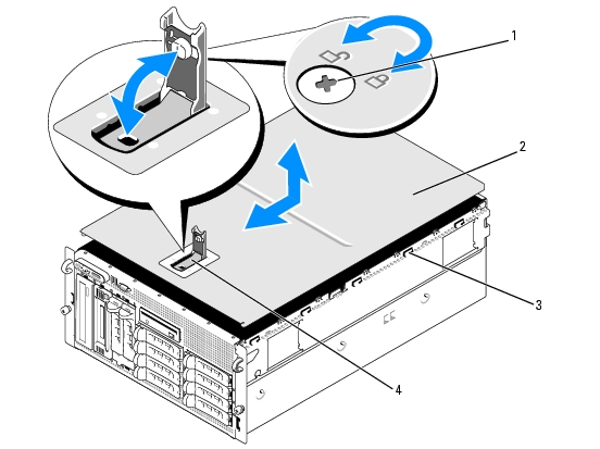
- To remove the system cover, turn the latch release lock on the cover latch counterclockwise to the
unlocked position. See Figure 3-4.
- Lift up on the latch on top of the system. See Figure 3-4.
- Grasp the cover on both sides and carefully lift the cover away from the system.
Closing the System
- Lift up on the cover latch.
- Place the cover on top of the system and offset the cover slightly back so that it clears the chassis J
hooks and lays flat on the system chassis. See Figure 3-4.
- Push the latch down to lever the cover into the closed position.
- Turn the latch release lock clockwise to the locked position. See Figure 3-4.
- Replace the Kensington cable lock on the back of the chassis. See Figure 1-4 for the location of the lock
slot on the back of the chassis.
Figure 3-4. Installing and Removing the System Cover
|
1
|
latch release lock
|
2
|
system cover
|
3
|
chassis hooks
|
|
4
|
cover latch
|
|
|
|
|
Hot-Plug Hard Drives
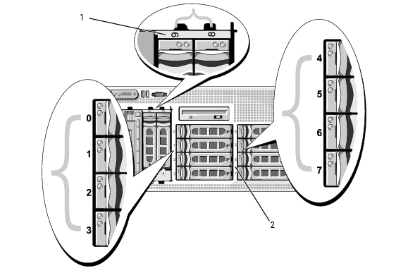
Figure 3-5 shows how the SAS/SATA hot-plug drive bays are numbered in the rack-mount orientation.
|
|
NOTE: For the tower orientation, drive bays 8 and 9 are reversed. |
Figure 3-5. Hard-Drive Bay Numbers (Rack)
|
1
|
1x2 flex bay hard drives
|
2
|
1x8 backplane hard drives
|
Before You Begin
Hard drives are supplied in special hot-pluggable drive carriers that fit in the hard-drive bays. Depending on your configuration, you received one of the following two drive carrier types:
- SATA drive carrier — Usable only with a SATA hard drive.
- SATAu drive carrier — Usable with either a SAS hard drive or a SATA hard drive with a universal interposer card. The interposer card provides enhanced functionality that makes the SATA hard drive usable in some storage systems.

|
NOTICE: Before attempting to remove or install a drive while the system is running, see the documentation for the optional SAS RAID controller daughter card to ensure that the host adapter is configured correctly to support hot-plug drive removal and insertion. |
|
|
NOTE: It is recommended that you use only drives that have been tested and approved for use with the SAS backplane board. |
You may need to use different programs than those provided with the operating system to partition and format SAS or SATA hard drives.
|
|
NOTICE: Do not turn off or reboot your system while the drive is being formatted. Doing so can cause a drive failure. |
When you format a high-capacity hard drive, allow enough time for the formatting to be completed. Long format times for these drives are normal. A 9-GB hard drive, for example, can take up to 2.5 hours to format.
Removing a Drive Blank
|
|
NOTICE: To maintain proper system cooling, all empty hard-drive bays must have drive blanks installed. If you remove a hard-drive carrier from the system and do not reinstall it, you must replace the carrier with a drive blank. |
- Remove the front bezel, if attached. See Removing the Bezel.
- Insert your finger under the shrouded end of the blank and press in on the latch to eject the blank
outward from the bay.
- Pry the ends of the blank outward until the blank is free.
Installing a Drive Blank
The drive blank is keyed to ensure correct insertion into the drive bay. To install a drive blank, insert the blank into the drive bay and press evenly on the ends of the blank until it is fully inserted and latched.
Removing a Hot-Plug Hard Drive
- Remove the front bezel, if attached. See Removing the Bezel.
- From the RAID management software, prepare the drive for removal and wait until the hard-drive
indicators on the drive carrier signal that the drive can be removed safely. See your SAS RAID
controller documentation for information about hot-plug drive removal.
If the drive has been online, the green activity/fault indicator will flash as the drive is powered down. When both drive indicators are off, the drive is ready for removal.
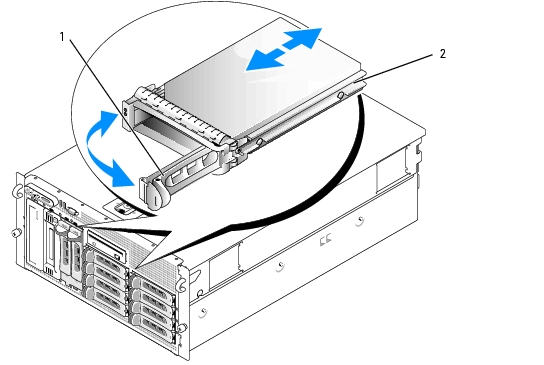
- Open the drive carrier release handle to release the drive. See Figure 3-6.
- Slide the hard drive out until it is free of the drive bay.
- If you do not replace the hard drive, insert a drive blank in the vacated drive bay. See Installing a Drive
Blank.
|
|
NOTICE: To maintain proper system cooling, all empty hard-drive bays must have drive blanks installed. |
Installing a Hot-Plug Hard Drive
- Remove the front bezel, if attached. See Removing the Bezel.
- If a drive blank is present in the bay, remove it. See Removing a Drive Blank.
- Install the hot-plug hard drive.
- Open the handle on the hard-drive carrier.
Figure 3-6. Installing a Hot-Plug Hard Drive
|
1
|
drive carrier release handle
|
2
|
drive carrier
|
- Insert the hard-drive carrier into the drive bay until the carrier contacts the backplane.
- Close the handle to lock the drive in place.
- Replace the front bezel, if it was removed in step 1.
Replacing a Hard-Drive Carrier
Removing a Hard Drive From a Hard-Drive Carrier
- If you are removing a SATA hard drive from a SATAu drive carrier, remove the interposer card:
- Viewing the hard drive carrier from the rear, locate the release lever on the left end of the
interposer card.
- Push the lever away from the carrier rail to release the left end of the card.
- Rotate the left end away from the hard drive to release the connector.
- Pull the right end of the interposer card clear of the slots in the carrier rail.
- Remove the four screws from the slide rails on the hard-drive carrier and separate the hard drive from
the carrier.
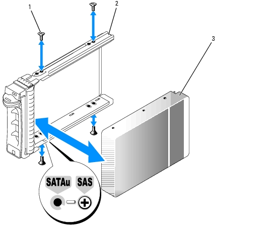
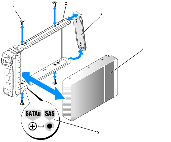
Installing a SAS Hard Drive Into a SATAu Drive Carrier
|
|
NOTE: SAS hard drives must be installed only in SATAu drive carriers. The SATAu drive carrier is labeled "SATAu" and also has marks indicating the SAS and SATA mounting screws. |
- Insert the SAS hard drive into the hard-drive carrier with the connector end of the drive at the rear.
See Figure 3-7.
- Viewing the assembly as shown in Figure 3-7, align the bottom rear screw hole on the hard drive
with the hole labeled "SAS" on the hard drive carrier.
When aligned correctly, the rear of the hard drive will be flush with the rear of the hard-drive carrier.
- Attach the four screws to secure the hard drive to the hard-drive carrier. See Figure 3-7.
Figure 3-7. Installing a SAS Hard Drive Into a Drive Carrier
|
1
|
screws (4)
|
2
|
SATAu drive carrier
|
3
|
SAS hard drive
|
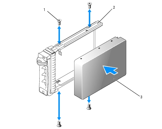
Installing a SATA Hard Drive Into a SATA Drive Carrier
|
|
NOTE: SATA hard drives that connect directly to the SAS backplane must be installed in SATA drive carriers (labeled "SATA"). Only SATA hard drives with interposer cards can be installed in SATAu drive carriers. |
- Insert the SATA hard drive into the hard-drive carrier with the connector end of the drive at the
rear. See Figure 3-8.
- Align the screw holes on the hard drive with the holes on the hard-drive carrier. See Figure 3-8.
- Attach the four screws to secure the hard drive to the hard-drive carrier. See Figure 3-8.
Figure 3-8. Installing a SATA Hard Drive Into a SATA Drive Carrier
|
1
|
screws (4)
|
2
|
SATA drive carrier
|
3
|
SATA hard drive
|
Installing a SATA Hard Drive and Interposer Card Into a SATAu Hard-Drive Carrier
|
|
NOTE: When you install a SATA hard drive into a SATAu drive carrier, you must install an interposer card onto the back of the hard drive. The SATAu drive carrier is labeled "SATAu" and also has marks indicating the SAS and SATA mounting screws. |
- Insert the SATA hard drive into the SATAu hard-drive carrier with the connector end of the drive at
the rear. See Figure 3-9.
- Viewing the assembly as shown in Figure 3-9, align the bottom rear screw hole on the hard drive
with the hole labeled "SATAu" on the hard drive carrier.
When aligned correctly, the rear of the interposer will be flush with the rear of the hard-drive carrier.
- Attach the four screws to secure the hard drive to the hard-drive carrier. See Figure 3-9.
- Attach the interposer card to the rear of the SATA hard drive:
- Angle the top of the interposer card into the inside top carrier rail so that the tabs on the
interposer card bracket attach to the slots on the inside of the carrier rail. See Figure 3-9.
- Rotate the bottom end of the card toward the hard drive to seat the connector. See Figure 3-9.
- Push the bottom end of the card to the hard drive until the latch on the card bracket clicks into
place.
Figure 3-9. Installing a SATA Hard Drive and Interposer Card Into a SATAu Drive Carrier
|
1
|
screws (4)
|
2
|
SATAu drive carrier
|
3
|
interposer card (SATA only)
|
|
4
|
SATA hard-drive
|
5
|
hole labels
|
|
|
Power Supplies
Your system supports one or two power supplies rated at an output of 930 W. If only one power supply is installed, it must be installed in the left power supply bay (1). If two power supplies are installed, the second power supply serves as a redundant, hot-plug power source.
|
|
NOTICE: To ensure proper system cooling, the power supply blank must be installed on the unoccupied power supply bay in a non-redundant configuration. |
Removing a Power Supply
|
|
NOTICE: The system requires one power supply for the system to operate normally. The system is in the redundant mode when two power supplies are installed and both power supplies are connected to an AC power source. Remove and replace only one power supply at a time in a system that is powered on. |
|
|
NOTE: On a rack system, you may have to unlatch and lift the cable management arm if it interferes with power supply removal. For information about the cable management arm, see the system's Rack Installation Guide. |
- If your system has a single power supply, turn off the system and all attached peripherals. For a
redundant system, you can leave the system running and proceed to the next step.
- Disconnect the power supply power cable from the power source.
- Disconnect the power cable from the power supply and remove the cable from the cable retention
bracket.
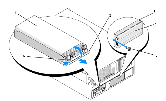
- Release the locking tab on the left side of the power supply, open the handle, and slide the power
supply out of the chassis. See Figure 3-10.
Figure 3-10. Installing and Removing a Power Supply
|
1
|
power supply
|
2
|
handle
|
3
|
tab
|
|
4
|
power supply blank
|
5
|
screw
|
6
|
locking tab
|
Installing a Power Supply
- If you are adding a second power supply, remove the power supply blank. See Removing the Power
Supply Blank.
- Holding the handle in the open position, slide the new power supply into the chassis until the
release lever contacts the system chassis. See Figure 3-10.
|
|
NOTICE: On a rack system, you may need to temporarily unlatch and lift the cable management arm. For information about the cable management arm, see the system's Rack Installation Guide. |
- Close the handle until the power supply is fully seated and the locking tab snaps into place.
- Connect the power cable to the power supply and the power outlet. Create a strain-relief loop in the
cable at the back of the power supply and attach the cable to the cable retention bracket just past
the loop. See the Getting Started Guide.
After installing a new power supply in a system with two power supplies, allow several seconds for the system to recognize the power supply and determine its status. The power-supply status indicator turns green to signify that the power supply is functioning properly (see Figure 1-5).
Removing the Power Supply Blank
Using a Phillips screwdriver, remove the screw on the left side of the blank, rotate the blank slightly to clear the bay, and remove from the chassis. See Figure 3-10.
|
|
NOTICE: To ensure proper system cooling, the power supply blank must be installed on the unoccupied power supply bay in a non-redundant configuration. Remove the power supply blank only if you are installing a second power supply. |
Installing the Power Supply Blank
To install the power supply blank, insert the tab on the right edge of the blank into the slot in the power supply bay wall. Rotate the blank into the power supply bay and secure with the Phillips screw. See Figure 3-10.
Fans
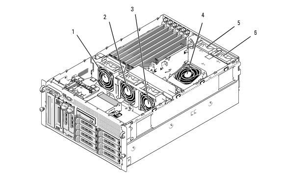
The system contains six hot-plug cooling fans:
- One expansion-bay cooling fan (fan 1)
- Two processor cooling fans, one for each processor (fans 2 and 3)
- Three memory module cooling fans:
- One fan on top of the memory cooling shroud (fan 4)
- Two fans at the rear of the system (fans 5 and 6)
|
|
NOTICE: In the event of a problem with a particular fan, the fan's number is referenced by the systems management software, allowing you to easily identify and replace the proper fan. |
Figure 3-11 shows the positions and identification numbers of the fans.
Figure 3-11. Cooling Fans
|
1
|
expansion-card fan (FAN1)
|
2
|
processor fan (FAN2)
|
3
|
processor fan (FAN3)
|
|
4
|
memory module fan (FAN4)
|
5
|
memory module fan (FAN5)
|
6
|
memory module fan (FAN6)
|
Removing and Installing a Fan
|
|
CAUTION: Only trained service technicians are authorized to remove the system cover and access any of the components inside the system. See your Product Information Guide for complete information about safety precautions, working inside the computer, and protecting against electrostatic discharge. |
- Open the system. See Opening the System.
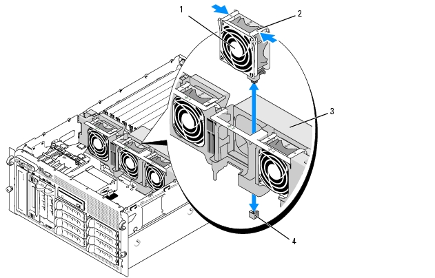
- Squeeze the release latches on top of the fan and lift the fan out of the fan bracket. See Figure 3-12.
|
|
NOTICE: Do not remove more than one fan at a time and do not operate the system with any fan removed for an extended period of time. Overheating can occur, resulting in a system shutdown and loss of data. |
- To replace the fan, align the connector on the fan with the fan connector on the system board and
insert the fan into the fan bracket.
The fan will start when it seats into the connector.
- Close the system. See Closing the System.
Figure 3-12. Installing and Removing a Fan From the Fan Brackets
|
1
|
fan
|
2
|
release latch (2)
|
3
|
center fan bracket
|
|
4
|
fan connector on system board
|
|
|
|
|
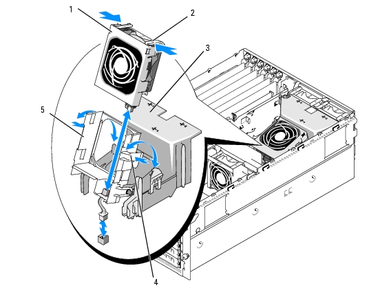
Removing or Installing the Cooling Shroud Fan
|
|
CAUTION: Only trained service technicians are authorized to remove the system cover and access any of the components inside the system. See your Product Information Guide for complete information about safety precautions, working inside the computer, and protecting against electrostatic discharge. |
|
|
NOTICE: Never remove the memory cooling shroud without first powering down the system. Overheating of the system can develop quickly resulting in a shutdown of the system and the loss of data. |
- Remove the front bezel, if attached. See Removing the Bezel.
- Open the system. See Opening the System.
- Release the fan bracket from the cooling shroud by squeezing the blue latches on each side of the
fan bracket, and then rotate the bracket to the up position. See Figure 3-13.
|
|
NOTE: Do not remove the cooling shroud from the system to perform this step. |
- Remove the fan from the bracket by squeezing the release handles on top of the fan and pulling the
fan out of the bracket. See Figure 3-13.
|
|
NOTICE: Do not remove more than one fan from the system at a time and do not operate the system with any fan removed for an extended period of time. Overheating can occur resulting in a system shutdown and loss of data. |
- Replace the fan.
- Rotate the fan bracket toward the shroud and slightly squeeze the side tabs so that the tabs enter the
latch slots.
- Close the system. See Closing the System.
- Replace the front bezel, if removed.
Figure 3-13. Removing and Replacing the Cooling Shroud Fan
|
1
|
fan
|
2
|
fan release latch (2)
|
3
|
cooling shroud
|
|
4
|
fan bracket latch (2)
|
5
|
fan bracket
|
|
|
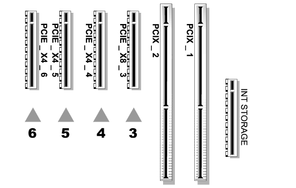
Expansion Cards
Your system provides six full-length expansion card slots configured as follows:
- Slot 1 and 2 are 64-bit, 133-MHz (3.3-V) PCI-X expansion slots. These slots will accommodate 133-MHz, 100-MHz, 66-Hz, and 33-MHz PCI cards and PCI-X cards.
- Slot 3 is a x8 lane-width PCIe expansion slot.
- Slots 4, 5, and 6 are x4 lane-width PCIe expansion slots.
Figure 3-14 shows the relative locations of these expansion-card slots
Figure 3-14. Expansion Slots
Installing an Expansion Card
|
|
CAUTION: Only trained service technicians are authorized to remove the system cover and access any of the components inside the system. See your Product Information Guide for complete information about safety precautions, working inside the computer, and protecting against electrostatic discharge. |
- Turn off the system and attached peripherals, and disconnect the system from the electrical outlet.
- Open the system. See Opening the System.
- Open the plastic expansion-card retainer adjacent to the back of the empty slot. See Figure 3-15.
Figure 3-15. Installing and Removing Expansion Cards
|
1
|
card-edge guide
|
2
|
expansion card
|
3
|
expansion-card retainer
|
- Remove the filler bracket on the slot you will be using.
|
|
NOTE: Keep this bracket if you need to remove the expansion card. Filler brackets must be installed over empty expansion-card slots to maintain Federal Communications Commission (FCC) certification of the system. The brackets also keep dust and dirt out of the system and aid in proper cooling and airflow inside the system. |
- Align the expansion card with the card-edge guides and insert the expansion card firmly into the
expansion-card connector until the card is fully seated.
|
|
NOTE: Ensure that the expansion-card bracket is also inserted into the securing slot on the back of the expansion-card cage. |
- Close the expansion-card retainer. See Figure 3-15.
- Connect any internal or external cable(s) to the expansion card.
- Close the system. See Closing the System.
Removing an Expansion Card
|
|
CAUTION: Only trained service technicians are authorized to remove the system cover and access any of the components inside the system. See your Product Information Guide for complete information about safety precautions, working inside the computer, and protecting against electrostatic discharge. |
- Turn off the system and attached peripherals, and disconnect the system from the electrical outlet.
- Open the system. See Opening the System.
- Disconnect any internal or external cable(s) that are connected to the expansion card.
- Open the expansion-card retainer adjacent to the slot. See Figure 3-15.
- Grasp the expansion card and carefully remove it from the socket connector.
- If you are permanently removing the card, replace the metal filler bracket over the empty card-slot
opening.
|
|
NOTE: Filler brackets must be installed over empty expansion-card slots to maintain FCC certification of the system. The brackets also keep dust and dirt out of the system and aid in proper cooling and airflow inside the system. |
- Close the expansion-card retainer. See Figure 3-15.
- Close the system. See Closing the System.
Internal SCSI Tape Backup Unit
Removing an Internal SCSI Tape Backup Unit
|
|
CAUTION: Only trained service technicians are authorized to remove the system cover and access any of the components inside the system. See your Product Information Guide for complete information about safety precautions, working inside the computer, and protecting against electrostatic discharge. |
- Turn off the system, including any attached peripherals, and disconnect the system from the electrical
outlet.
- Remove the front bezel, if attached. See Removing the Bezel.
- Open the system. See Opening the System.
- Push the spring-loaded release latch on top of the peripheral bay to left and eject the tape backup unit
partially out of the bay. See Figure 3-16.
- Disconnect the ribbon and power cables on the back of the unit.
- Remove the tape backup unit from the system.
- If you are not replacing the unit, insert the filler plate(s) in the peripheral bay.
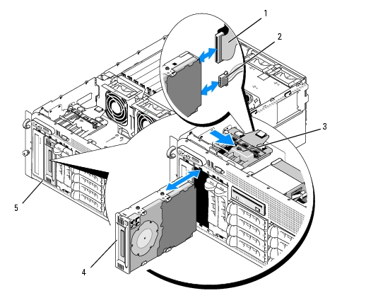
Figure 3-16. Installing and Removing the Half-Height Tape Backup Unit or Optical Drive
|
1
|
IDE or SCSI ribbon cable
|
2
|
power cable
|
3
|
release latch
|
|
4
|
half-height tape backup unit or optical drive
|
5
|
peripheral bay
|
|
|
Installing an Internal SCSI Tape Backup Unit
This subsection describes how to configure and install an internal SCSI tape backup unit in the peripheral bay.
|
|
CAUTION: Only trained service technicians are authorized to remove the system cover and access any of the components inside the system. See your Product Information Guide for complete information about safety precautions, working inside the computer, and protecting against electrostatic discharge. |
- Turn off the system, including any attached peripherals, and disconnect the system from the electrical
outlet.
- Remove the front bezel, if attached. See Removing the Bezel.
- Open the system. See Opening the System.
- Unpack the tape drive (and controller card, if applicable) and configure the tape drive according to
the documentation that came with the tape drive, based on the following guidelines:
- Each device attached to a SCSI host adapter must have a unique SCSI ID number. (Narrow SCSI
devices use IDs 0 to 7; wide SCSI devices use IDs from 0 to 15). Set the drive's SCSI ID to avoid
conflicts with other devices on the SCSI bus. For the default SCSI ID setting, see the
documentation provided with the drive.
|
|
NOTE: There is no requirement that SCSI ID numbers be assigned sequentially or that devices be attached to the cable in order by ID number. |
- SCSI logic requires that the two devices at opposite ends of a SCSI chain be terminated and that
all devices in between be unterminated. Therefore, you enable the tape drive's termination if it is
the last device in a chain of devices (or sole device) connected to the SCSI controller.
- If a controller card was included in the drive kit, install the card now. See Installing an Expansion
Card.
- Remove the filler plate(s) from the peripheral bay.
|
|
NOTE: For a full-height tape backup unit, you must remove two filler plates. |
- If the mounting screws are not attached to the drive, install them now.
- Insert the new tape drive three-quarters of the way into the drive slot on the peripheral bay, with the
mounting screws entering the bay slide slots.
- Connect the SCSI interface cable in the drive kit to the drive. See Figure 3-16.
- Connect the SCSI interface cable to the SCSI connector on the optional SCSI controller card.
- Connect the power cable to the power connector on the drive. If not already done, connect the
other end of the power cable to the CD/TBU power connector on the SAS backplane. See
Figure 6-3.
- Push the tape drive the rest of the way into the bay until the spring latch engages.
- Close the system. See Closing the System.
- Replace the front bezel, if it was removed in step 1.
- Reconnect the system and peripherals to their electrical outlets, and turn them on.
- Finish configuring the SCSI tape backup unit according to the documentation you received with the
device.
- Perform a tape backup and verification test with the drive as instructed in the software documentation
that came with the drive.
Optical Drive
Removing an Optical Drive
|
|
CAUTION: Only trained service technicians are authorized to remove the system cover and access any of the components inside the system. See your Product Information Guide for complete information about safety precautions, working inside the computer, and protecting against electrostatic discharge. |
- Turn off the system, including any attached peripherals, and disconnect the system from the electrical
outlet.
- Remove the front bezel, if attached. See Removing the Bezel.
- Open the system. See Opening the System.
- Disconnect the cables from the SAS controller daughter card on the expansion-bay bracket and pull
the cables out of the way of the center fans.
- Remove the fans from the center fan bracket. See Removing and Installing a Fan.
- Remove the center fan bracket. See Removing the Center Fan Bracket.
- Push the spring latch at the top of the peripheral bay to the right and partially extend the optical
drive out of the bay. See Figure 3-16.
- Remove the ribbon cable and the power cable from the back of the optical drive.
- Remove the optical drive from the bay.
- Replace the optical drive or insert the filler plate over the empty drive slot.
- Replace the center fan bracket. See Replacing the Center Fan Bracket.
- Replace the fans into the center fan bracket.
- Reconnect the cables to the SAS controller daughter card.
- Close the system. See Closing the System.
- Replace the front bezel, if removed in step 2.
- Reconnect the system and peripherals to their electrical outlets.
Installing an Optical Drive
|
|
CAUTION: Only trained service technicians are authorized to remove the system cover and access any of the components inside the system. See your Product Information Guide for complete information about safety precautions, working inside the computer, and protecting against electrostatic discharge. |
- Turn off the system, including any attached peripherals, and disconnect the system from the electrical
outlet.
- Remove the front bezel, if attached. See Removing the Bezel.
- Open the system. See Opening the System.
- Remove the filler plate from the drive slot on the peripheral bay.
- Disconnect the cables from the SAS controller daughter card on the expansion-bay bracket and pull
the cables out of the way of the center fans.
- Remove the fans from the center fan bracket. See Removing and Installing a Fan.
- Remove the center fan bracket. See Removing the Center Fan Bracket.
- If the mounting screws are not attached to the drive, install them now.
- Insert the new optical drive three-quarters of the way into the drive slot on the peripheral bay, with
the mounting screws entering the bay slide slots. See Figure 3-16.
- Attach one end of the ribbon cable to the IDE connector on the system board (see Figure 6-2) and
the other end to the connector on the rear of the optical drive.
- Attach the power cable to the CD power connector (CD/TBU) at the top of the SAS backplane
board (see Figure 6-3) and to the power connector on the rear of the optical drive.
- Push the optical drive the rest of the way into the bay until the spring latch engages.
- Replace the center fan bracket. See Replacing the Center Fan Bracket.
- Replace the fans into the center fan bracket.
- Reconnect the cables to the SAS controller daughter card.
- Close the system. See Closing the System.
- Replace the front bezel, if removed in step 2.
- Reconnect the system and peripherals to their electrical outlets.
Diskette Drive
Removing the Diskette Drive
|
|
CAUTION: Only trained service technicians are authorized to remove the system cover and access any of the components inside the system. See your Product Information Guide for complete information about safety precautions, working inside the computer, and protecting against electrostatic discharge. |
- Turn off the system, including any attached peripherals, and disconnect the system from the electrical
outlet.
- Remove the front bezel, if attached. See Removing the Bezel.
- Open the system. See Opening the System.
- Disconnect the power cable and ribbon cable from the back of the diskette drive.
- Release the diskette drive carrier from the top of the peripheral bay.
- Push inward on the plastic tab on the side of the carrier until the tab clears the metal stop.
- Slide the carrier back and lift out of the chassis. See Figure 3-17.
Figure 3-17. Installing and Removing the Diskette Drive
|
1
|
diskette drive
|
2
|
diskette drive ribbon cable
|
3
|
diskette drive power cable
|
|
4
|
diskette drive carrier
|
5
|
release tab
|
6
|
metal stop
|
|
7
|
drive bay tabs
|
|
|
|
|
Installing the Diskette Drive Into the Drive Carrier
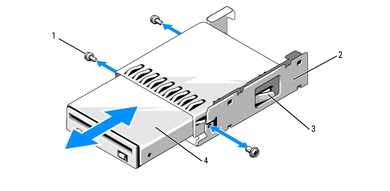
Place the diskette drive into the drive carrier with the connectors toward the back, align the screw holes, and secure with the three Phillips screws. See Figure 3-18.
Figure 3-18. Installing the Diskette Drive Into the Drive Carrier
|
1
|
screws (3)
|
2
|
diskette drive carrier
|
3
|
plastic latch
|
|
4
|
diskette drive
|
|
|
|
|
Installing the Diskette Drive
|
|
CAUTION: Only trained service technicians are authorized to remove the system cover and access any of the components inside the system. See your Product Information Guide for complete information about safety precautions, working inside the computer, and protecting against electrostatic discharge. |
- Turn off the system, including any attached peripherals, and disconnect the system from the
electrical outlet.
- Remove the front bezel, if attached. See Removing the Bezel.
- Open the system. See Opening the System.
- If a diskette drive ribbon cable is already connected to your system board, skip to the next step.
Otherwise, do the following:
- Disconnect the cables from the SAS controller daughter card on the expansion-bay bracket and
pull the cables out of the way of the center fan bracket.
- Remove the fans from the center fan bracket. See Removing and Installing a Fan.
- Remove the center fan bracket. See Removing the Center Fan Bracket.
- To remove the diskette drive filler plate, pull the retention spring slightly away from the filler plate,
then lift the filler plate from the carrier.
- Install the diskette drive carrier into the system:
- Align the slots on the bottom of the diskette drive carrier with the drive bay tabs on top of the
peripheral bay and lower the carrier unto the tabs.
- Push the carrier toward the system front plate until the plastic latch on the carrier locks into
position.
- Attach one end of the ribbon cable to the floppy connector on the system board and the other end to
the connector on the rear of the diskette drive.
- Attach the power cable to the floppy connector (FDD) at the top of the SAS backplane board (see
Figure 6-3) and to the power connector on the rear of the diskette drive.
- If applicable, replace the components your removed in step 4:
- Replace the center fan bracket. See Replacing the Center Fan Bracket.
- Replace the fans into the center fan bracket.
- Reconnect the cables to the SAS controller daughter card.
- Close the system. See Closing the System.
- Replace the front bezel, if removed in step 2.
- Reconnect the system and peripherals to their electrical outlets.
System Battery
Replacing the System Battery
|
|
CAUTION: Only trained service technicians are authorized to remove the system cover and access any of the components inside the system. See your Product Information Guide for complete information about safety precautions, working inside the computer, and protecting against electrostatic discharge. |
- Enter the System Setup program and record the option settings on the System Setup screens. See
Using the System Setup Program.
- Turn off the system, including any attached peripherals, and disconnect the system from the electrical
outlet.
- Open the system. See Opening the System.
- See Figure 6-2 for the location of the system battery and then, starting with PCI slot 6, remove as
many expansion cards as you need to create enough room in the expansion bay to work with the
system battery. See Removing an Expansion Card.
- Remove the system battery.
|
|
NOTICE: To avoid damage to the battery connector, you must firmly support the connector while installing or removing a battery. |
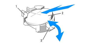
- Support the battery connector by pressing down firmly on the positive side of the connector.
See Figure 3-19.
- While supporting the battery connector, push the battery toward the positive side of the
connector and pry it up out of the securing tabs at the negative side of the connector.
Figure 3-19. Replacing the System Battery
|
1
|
positive side of connector
|
2
|
system battery
|
3
|
negative side of connector
|
- Install the new system battery with the side labeled "+" facing up. See Figure 3-19.
- Install the new system battery.
- Support the battery connector by pressing down firmly on the positive side of the connector.
- Hold the battery with the "+" facing up, and slide it under the securing tabs at the positive side of
the connector.
- Press the battery straight down into the connector until it snaps into place.
- Replace all the expansion cards you removed in step 4.
- Close the system. See Closing the System.
- Reconnect the system to the electrical outlet and turn on the system and attached peripherals.
- Enter the System Setup program to confirm that the battery operates properly.
- From the main screen, select System Time to enter the correct time and date.
- Re-enter any system configuration information that is no longer displayed on the System Setup
screens, and then exit the System Setup program.
- To test the newly installed battery, see Troubleshooting the System Battery.
Cooling Shroud
The cooling shroud produces and directs airflow over the system memory modules with an attached hot-plug fan. The fan need not be removed prior to removing the shroud.
Removing the Cooling Shroud
|
|
CAUTION: Only trained service technicians are authorized to remove the system cover and access any of the components inside the system. See your Product Information Guide for complete information about safety precautions, working inside the computer, and protecting against electrostatic discharge. |
- Turn off the system, including any attached peripherals, and disconnect the system from the electrical
outlet.
|
|
NOTICE: Never remove the memory cooling shroud without first powering down the system. Overheating of the system can develop quickly resulting in a shutdown of the system and the loss of data. |
- Open the system. See Opening the System.
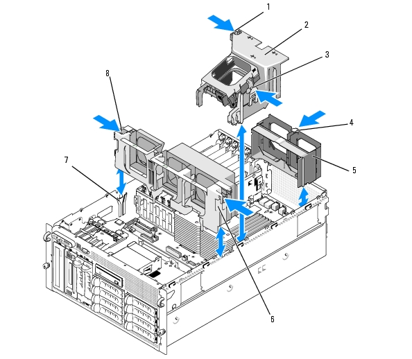
- To remove the cooling shroud, release the blue latches on the shroud by pulling each latch outward
from its securing tab. See Figure 3-20.
- Lift the shroud straight up to disengage the fan connector from the system board, and then lift the
shroud out of the system. See Figure 3-20.
|
|
CAUTION: The DIMMs are hot to the touch for some time after the system has been powered down. Allow time for the DIMMs to cool before handling them. Handle the DIMMs by the card edges and avoid touching the DIMM components. |
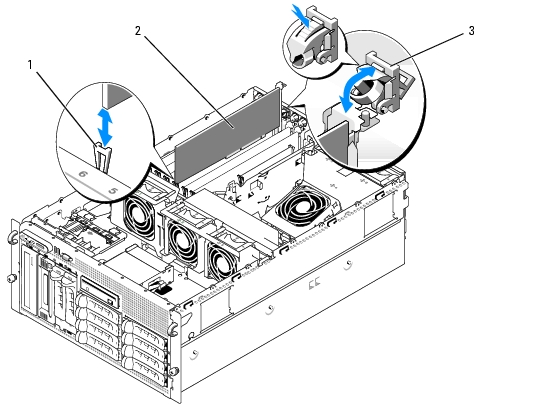
Figure 3-20. Installing and Removing the Fan Brackets and Cooling Shroud
|
1
|
cooling shroud latch (left)
|
2
|
cooling shroud
|
3
|
cooling shroud latch (right)
|
|
4
|
back fan bracket release latch
|
5
|
back fan bracket
|
6
|
center fan bracket
|
|
7
|
chassis slot
|
8
|
center fan bracket release latch (2)
|
|
|
Installing the Cooling Shroud
To install the cooling shroud, align the rails on the right side of the shroud with the tracks on the right chassis wall and then slowly lower the shroud straight down into the system until the fan connector engages and the latches snap into place. See Figure 3-20.
|
|
NOTICE: Never operate your system with the memory cooling shroud removed. Overheating of the system can develop quickly resulting in a shutdown of the system and the loss of data. |
Fan Brackets
Removing the Center Fan Bracket
|
|
CAUTION: Only trained service technicians are authorized to remove the system cover and access any of the components inside the system. See your Product Information Guide for complete information about safety precautions, working inside the computer, and protecting against electrostatic discharge. |
- Turn off the system, including any attached peripherals, and disconnect the system from the electrical
outlet.
- Remove the front bezel, if attached. See Removing the Bezel.
- Open the system. See Opening the System.
- Disconnect the cables from the SAS controller daughter card on the expansion bay bracket.
- Remove the fans from the center fan bracket. See Removing and Installing a Fan.
- To release the fan bracket, use your index fingers and push inward on the blue latches on each end
of the center fan bracket. Then slide the bracket straight up and out of the system. See Figure 3-20.
If the bracket does not disengage completely, push down slightly on the bracket when releasing the latches.
Replacing the Center Fan Bracket
- Align the rails on each end of the fan bracket with the guide rails on the chassis walls and lower the
bracket down into the system until the latches engage.
- Reattach the cables to the SAS controller daughter card on the expansion bay bracket.
- Replace the fans into the fan bracket.
- Close the system. See Closing the System.
- Replace the front bezel, if removed.
- Reconnect the system to the electrical outlet and turn on the system and attached peripherals.
Removing the Back Fan Bracket
|
|
CAUTION: Only trained service technicians are authorized to remove the system cover and access any of the components inside the system. See your Product Information Guide for complete information about safety precautions, working inside the computer, and protecting against electrostatic discharge. |
- Turn off the system, including any attached peripherals, and disconnect the system from the electrical
outlet.
- Remove the front bezel, if attached. See Removing the Bezel.
- Open the system. See Opening the System.
- Remove the memory cooling shroud. See Removing the Cooling Shroud.
- Remove the fans from the back fan bracket. See Removing and Installing a Fan.
- To remove the back fan bracket, push down on the blue latch along the rear chassis wall and slide
the bracket upwards. See Figure 3-20.
Replacing the Back Fan Bracket
- Slide the left and right edges of the bracket into the two corresponding channels on the inside of
the system chassis back panel. See Figure 3-20.
- Lower the bracket into the system until the two tabs on the top edge of the bracket fit into the slots in
the system back panel.
- Replace the memory cooling shroud.
|
|
NOTICE: Never operate your system with the memory cooling shroud removed. Overheating of the system can develop quickly resulting in a shutdown of the system and the loss of data. |
- Replace the fans into the fan bracket.
- Close the system. See Closing the System.
- Replace the front bezel, if removed.
- Reconnect the system to the electrical outlet and turn on the system and attached peripherals.
Memory
You can upgrade your system memory to a maximum of 48 GB by installing 533MHz or, when available, 667MHz fully buffered DIMMs (FBDs) in dual sets of 256-MB, 512-MB, 1-GB, 2-GB, or 4-GB. The memory sockets are located on the system board beneath the cooling shroud. See Figure 6-2.
|
|
NOTICE: If you remove your original memory modules from the system during a memory upgrade, keep them separate from any new memory modules that you may have. Use only 533 MHz or, when available, 667 MHz FBDs. |
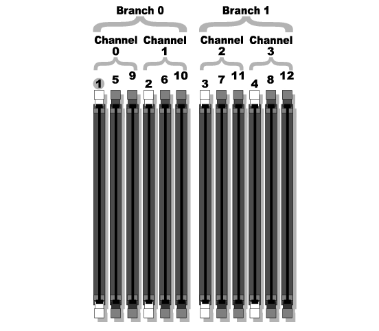
The memory module sockets are arranged on the system board in two equal branches (0 and 1). See Figure 3-21. Each branch consists of two channels:
- Channel 0 and channel 1 are in branch 0.
- Channel 2 and channel 3 are in branch 1.
Each channel consists of three DIMM sockets:
- Channel 0 contains DIMM_1, DIMM_5, and DIMM_9.
- Channel 1 contains DIMM _2, DIMM_6, and DIMM_10.
- Channel 2 contains DIMM_3, DIMM_7, and DIMM_11.
- Channel 3 contains DIMM _4, DIMM _8, and DIMM_12.
The first DIMM socket of each channel has white release tabs.
Figure 3-21. DIMM Sockets
General Memory Module Installation Guidelines
To ensure optimal performance of your system, observe the following guidelines when configuring your system memory.
- Use only qualified FBDs. FBDs can be either single-ranked or dual-ranked. FBDs marked with a 1R are single-ranked and modules marked with a 2R are dual-ranked.
- A minimum of two identical FBDs must installed.
- DIMM sockets must be populated by lowest number first.
- FBDs must be installed in pairs of matched memory size, speed, and technology, and the total number of FBDs in the configuration must total two, four, eight, or twelve. For best system performance, all four, eight, or twelve FBDs should be identical memory size, speed, and technology.
- Memory sparing and memory mirroring require eight or twelve FBDs, and all FBDs must be of identical memory size, speed, and technology.
- Memory sparing and memory mirroring cannot be implemented at the same time.
Non-Optimal Memory Configurations
System performance can be affected if your memory configuration does not conform to the preceding installation guidelines. Your system may issue an error message during startup stating that your memory configuration is non-optimal.
Memory Sparing Support
The system supports memory sparing if eight or twelve identical memory modules are installed in the system. The memory sparing feature must be enabled in the System Setup program and can be used only if memory mirroring is not enabled.
Memory sparing allocates four ranks of DIMM memory to the spare bank of memory sparing. These four ranks consist of the first rank of memory in DIMM sockets 1 through 4. For single-rank DIMMs, the entire capacity of the four DIMMs is allocated to sparing whereas for dual-rank DIMMs, only half of the four-DIMM capacity is allocated to sparing. Table 3-1 shows how memory sparing splits the available and spared memory in each of the single- and dual-ranked memory module combinations.
Table 3-1. Memory Sparing Configurations
|
DIMMs
|
Size/Type
|
Total Memory
|
Available
|
Spare
|
|---|
8
| 256-MB single-rank
| 2 GB
| 1 GB
| 1 GB
|
| 512-MB single-rank
| 4 GB
| 2 GB
| 2 GB
|
| 1-GB single-rank
| 8 GB
| 4 GB
| 4 GB
|
| 2-GB single-rank
| 16 GB
| 8 GB
| 8 GB
|
| 2-GB dual-rank
| 16 GB
| 12 GB
| 4 GB
|
| 4-GB dual-rank
| 32 GB
| 24 GB
| 8 GB
|
12
| 256-MB single-rank
| 3 GB
| 2 GB
| 1 GB
|
| 512-MB single-rank
| 6 GB
| 4 GB
| 2 GB
|
| 1-GB single-rank
| 12 GB
| 8 GB
| 4 GB
|
| 2-GB single-rank
| 24 GB
| 16 GB
| 8 GB
|
| 2-GB dual-rank
| 24 GB
| 20 GB
| 4 GB
|
| 4-GB dual-rank
| 48 GB
| 40 GB
| 8 GB
|
Memory Mirroring Support
The system supports memory mirroring if eight or twelve identical memory modules are installed in the system. Mirroring must be enabled in the System Setup program and can be used only if memory sparing is not enabled. In a mirrored configuration, the total available system memory is one-half of the total installed memory.
Installing Memory Modules
|
|
CAUTION: Only trained service technicians are authorized to remove the system cover and access any of the components inside the system. See your Product Information Guide for complete information about safety precautions, working inside the computer, and protecting against electrostatic discharge. |
- Turn off the system, including any attached peripherals, and disconnect the system from the electrical
outlet.
- Open the system. See Opening the System.
- Remove the memory cooling shroud. See Removing the Cooling Shroud.
|
|
NOTICE: Never remove the memory cooling shroud without first powering down the system. Overheating of the system can develop quickly resulting in a shutdown of the system and the loss of data. |
- Locate the memory module sockets on the system board. See Figure 6-2.
|
|
CAUTION: The DIMMs are hot to the touch for some time after the system has been powered down. Allow time for the DIMMs to cool before handling them. Handle the DIMMs by the card edges and avoid touching the DIMM components. |
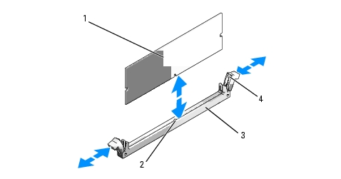
- Press the ejectors on the memory module socket down and out, as shown in Figure 3-22, to allow the
memory module to be inserted into the socket.
Figure 3-22. Installing and Removing a Memory Module
|
1
|
memory module
|
2
|
alignment key
|
3
|
socket
|
|
4
|
memory module socket ejectors (2)
|
|
|
|
|
- Align the memory module's edge connector with the alignment key on the memory module socket, and
insert the memory module in the socket.
|
|
NOTE: The memory module socket has an alignment key that allows you to install the memory module in the socket in only one way. |
- Press down on the memory module with your thumbs while pulling up on the ejectors with your index
fingers to lock the memory module into the socket.
When the memory module is properly seated in the socket, the ejectors on the memory module socket align with the ejectors on the other sockets that have memory modules installed.
- Repeat step 3 through step 7 of this procedure to install the remaining memory modules.
- Replace the memory cooling shroud.
|
|
NOTICE: Never operate your system with the memory cooling shroud removed. Overheating of the system can develop quickly resulting in a shutdown of the system and the loss of data. |
- Close the system. See Closing the System.
- Reconnect the system and peripherals to power and turn them on.
- (Optional) Press <F2> to enter the System Setup program, and check the System Memory setting on
the main System Setup screen.
The system should have already changed the value to reflect the newly installed memory.
- If the value is incorrect, one or more of the memory modules may not be installed properly. Repeat
step 2 through step 12 of this procedure, checking to ensure that the memory modules are firmly
seated in their sockets.
- Run the system memory test in the system diagnostics. See Running the System Diagnostics.
Removing Memory Modules
|
|
CAUTION: Only trained service technicians are authorized to remove the system cover and access any of the components inside the system. See your Product Information Guide for complete information about safety precautions, working inside the computer, and protecting against electrostatic discharge. |
- Turn off the system, including any attached peripherals, and disconnect the system from the electrical
outlet.
- Open the system. See Opening the System.
- Remove the memory cooling shroud. See Removing the Cooling Shroud.
|
|
NOTICE: Never remove the memory cooling shroud without first powering down the system. Overheating of the system can develop quickly resulting in a shutdown of the system and the loss of data. |
- Locate the memory module sockets on the system board. See Figure 6-2.
|
|
CAUTION: The DIMMs are hot to the touch for some time after the system has been powered down. Allow time for the DIMMs to cool before handling them. Handle the DIMMs by the card edges and avoid touching the DIMM components. |
- Press down and out on the ejectors on each end of the socket until the memory module pops out of
the socket. See Figure 3-22.
- Replace the memory cooling shroud.
|
|
NOTICE: Never operate your system with the memory cooling shroud removed. Overheating of the system can develop quickly resulting in a shutdown of the system and the loss of data. |
- Close the system. See Closing the System.
Installing a RAC Card
|
|
CAUTION: Only trained service technicians are authorized to remove the system cover and access any of the components inside the system. See your Product Information Guide for complete information about safety precautions, working inside the computer, and protecting against electrostatic discharge. |
- Turn off the system, including any attached peripherals, and disconnect the system from the electrical
outlet.
- Open the system. See Opening the System.
- Remove the cooling shroud by pulling the release latches outward from their securing tabs and
lifting the shroud out of the system. See Figure 3-20.
- Remove the filler plug from the system back panel. See Figure 3-23.
Figure 3-23. Installing a RAC Card
|
1
|
notch in card edge
|
2
|
back standoff
|
3
|
NIC connector cutout
|
|
4
|
RAC card
|
5
|
RAC connector 2
|
6
|
RAC connector 1
|
|
7
|
expansion-bay bracket
|
8
|
standoffs with card-edge clips (2)
|
|
|
- Angle the RAC card so that its NIC connector inserts through the back-panel RAC card opening.
See Figure 3-23.
- Attach the card to the expansion-bay bracket:
- Position the RAC card on the expansion-bay bracket so that the plastic standoff at the back of the
bracket inserts into the notch on the edge of the RAC card.
- Carefully press the back end of the card onto the two plastic standoffs until the clips on the
standoffs snap over the card edges. See Figure 3-23.
- Attach the ribbon cables to the RAC card connectors and to the RAC connectors on the system
board (see Figure 6-2):
|
|
NOTICE: Be careful when attaching cables to the system board that you do not damage the surrounding system board components. Be particularly careful that you do not push or bend the system capacitors near the connectors. |
- Connect one cable to connector 1 on the RAC card and to RAC_CONN1 on the system board.
- Connect the second cable to connector 2 on the RAC card and to RAC_CONN2 on the system
board.
- Reinstall the cooling shroud.
|
|
NOTICE: Never operate your system with the memory cooling shroud removed. Overheating of the system can develop quickly resulting in a shutdown of the system and the loss of data. |
- Close the system. See Closing the System.
- Reconnect the system to the electrical outlet and turn on the system and attached peripherals.
- Enter the System Setup program and verify that the setting for the RAC card has changed to reflect
the presence of the card. See Using the System Setup Program.
See the RAC card documentation for information on configuring and using the RAC card.
Activating the Integrated NIC TOE
To add TCP/IP Offload Engine (TOE) functionality to the system's integrated NIC, install the TOE NIC hardware key in the TOE_KEY socket on the system board (see Figure 6-2.)
Microprocessor
You can upgrade the system processor(s) to take advantage of future options in speed and functionality, or add a second processor. Each processor and its associated internal cache memory are contained in a land grid array (LGA) package that is installed in a ZIF socket on the system board.
Replacing a Processor
|
|
CAUTION: Only trained service technicians are authorized to remove the system cover and access any of the components inside the system. See your Product Information Guide for complete information about safety precautions, working inside the computer, and protecting against electrostatic discharge. |
- Prior to upgrading your system, download the latest system BIOS version on support.dell.com.
- Turn off the system, including any attached peripherals, and disconnect the system from the electrical
outlet.
- Open the system. See Opening the System.
- Remove the fans from the center fan bracket. See Removing and Installing a Fan.
- Remove the center fan bracket. See Removing the Center Fan Bracket.
|
|
NOTICE: When you remove the heat sink, the possibility exists that the processor might adhere to the heat sink and be removed from the socket. It is recommended that you remove the heat sink while the processor is still warm. |
|
|
NOTICE: Never remove the heat sink from a processor unless you intend to remove the processor. The heat sink is necessary to maintain proper thermal conditions. |
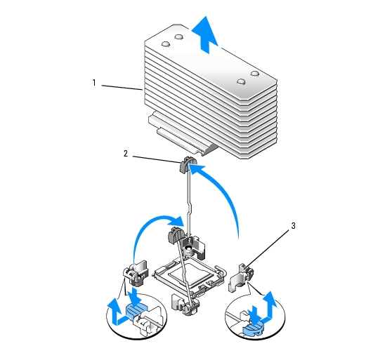
- Press the blue tab on the end of one of the heat-sink retention levers to disengage the lever, then lift
the lever 90 degrees. See Figure 3-24.
Figure 3-24. Installing and Removing the Heat Sink
|
1
|
heat sink
|
2
|
heat-sink retention lever (2)
|
3
|
retention lever latch
|
- Wait 30 seconds for the heat sink to loosen from the processor.
- Open the other heat sink retention lever.
- If the heat sink has not separated from the processor, carefully rotate the heat sink in a clockwise, then
counterclockwise, direction until it releases from the processor. Do not pry the heat sink off of the
processor.
- Lift the heat sink off of the processor and set the heat sink aside.
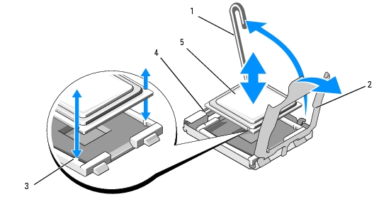
- Pull the socket-release lever 90 degrees upward until the processor is released from the socket. See
Figure 3-25.
- Rotate the processor shield upward and out of the way.
Figure 3-25. Installing and Removing a Processor
|
1
|
socket-release lever
|
2
|
processor shield
|
3
|
socket key (2)
|
|
4
|
ZIF socket
|
5
|
processor
|
|
|
- Lift the processor out of the socket and leave the release lever up so that the socket is ready for the
new processor.
|
|
NOTICE: Be careful not to bend any of the pins on the ZIF socket when removing the processor. Bending the pins can permanently damage the system board. |
- Unpack the new processor.
- Align the processor with the socket keys on the ZIF socket. See Figure 3-25.
- Install the processor in the socket.
|
|
NOTICE: Positioning the processor incorrectly can permanently damage the system board or the processor when you turn it on. When placing the processor in the socket, be careful not to bend the pins in the socket. |
- If the release lever on the processor socket is not positioned all the way up, move it to that
position.
- With the processor and the socket keys aligned, set the processor lightly in the socket, making
sure all pins are matched with the correct holes in the socket.
|
|
NOTICE: Do not use force to seat the processor. When the processor is positioned correctly, it engages easily into the socket. |
- When the processor is fully seated in the socket, rotate the socket release lever back down until
it snaps into place, securing the processor. See Figure 3-25.
- Close the processor cover. See Figure 3-25.
- Install the heat sink.
- Using a clean lint-free cloth, remove the existing thermal grease from the heat sink.
|
|
NOTE: If you did not receive a replacement heat sink, use the heat sink that you removed in step 10. |
- Remove the protective sheet from the thermal grease layer on top of the processor. If you
receive the processor without the thermal grease pre-applied, open the grease packet included
with your processor kit and apply thermal grease evenly to the top of the processor.
- Place the heat sink onto the processor. See Figure 3-24.
- Close one of the two heat sink retention levers until it locks. See Figure 3-24.
- Repeat for the other heat sink retention lever.
- Reinstall the fans in the center fan bracket. See Removing and Installing a Fan.
- Reinstall the center fan bracket. See Replacing the Center Fan Bracket.
- Close the system. See Closing the System.
- Reconnect the system to the electrical outlet and turn on the system and attached peripherals.
As the system boots, it detects the presence of the new processor and automatically changes the system configuration information in the System Setup program.
- Press <F2> to enter the System Setup program, and check that the processor information matches the
new system configuration. See Using the System Setup Program for instructions about using the
System Setup program.
- Run the system diagnostics to verify that the new processor operates correctly. See Running the
System Diagnostics for information about running the diagnostics and troubleshooting processor
problems.
1x8 SAS Backplane Board
Removing the 1x8 SAS Backplane Board
|
|
CAUTION: Only trained service technicians are authorized to remove the system cover and access any of the components inside the system. See your Product Information Guide for complete information about safety precautions, working inside the computer, and protecting against electrostatic discharge. |
- Remove the front bezel, if attached. See Removing the Bezel.
- Turn off the system and attached peripherals, and disconnect the system from the electrical outlet
and peripherals.
- Open the system. See Opening the System.
- Disconnect the cables from the SAS controller daughter card on the expansion bay bracket and remove
the cables from the center fan bracket.
- Remove the fans from the center fan bracket. See Removing and Installing a Fan.
- Remove the center fan bracket. See Removing the Center Fan Bracket.
- Disconnect all cables from the SAS backplane. See Figure 6-3.
- Unlock and slide the hard drive(s) out of the system at least 5 cm (2 inches).
|
|
NOTICE: If you completely remove the drives from the system, you must note the number of each drive and temporarily label them before removal, so you can replace them in the same locations. |
- Remove the SAS backplane:
- Lift the spring-loaded blue retention pin to release the backplane and then slide the backplane
upward.
- When the backplane cannot slide upward any farther, pull the backplane toward the back of the
system to remove it from the retention hooks.
Installing the 1x8 SAS Backplane Board
- Insert the backplane into the system behind the drive bays.
Ensure that all cables are out of the way when installing the new backplane.
- Align the backplane with the retention hooks on the chassis, then fit the backplane onto the
retention hooks.
- Slide the backplane downward until the blue retention pin snaps into place.
- Reconnect all cables to the backplane, being very careful to install them in their original locations.
- Reinsert the hard drives.
- Reinstall the fans in the center fan bracket. See Removing and Installing a Fan.
- Reinstall the center fan bracket. See Replacing the Center Fan Bracket.
- Close the system. See Closing the System.
- Replace the front bezel, if removed.
- Reconnect the system to the electrical outlet and turn on the system and attached peripherals.
Optional 1x2 Flex Bay Drive Bracket
Removing the 1x2 Flex Bay Drive Bracket
|
|
CAUTION: Only trained service technicians are authorized to remove the system cover and access any of the components inside the system. See your Product Information Guide for complete information about safety precautions, working inside the computer, and protecting against electrostatic discharge. |
- Remove the front bezel, if attached. See Removing the Bezel.
- Turn off the system and attached peripherals, and disconnect the system from the electrical outlet and
peripherals.
- Open the system. See Opening the System.
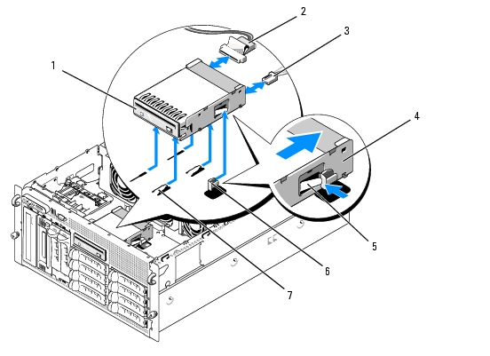
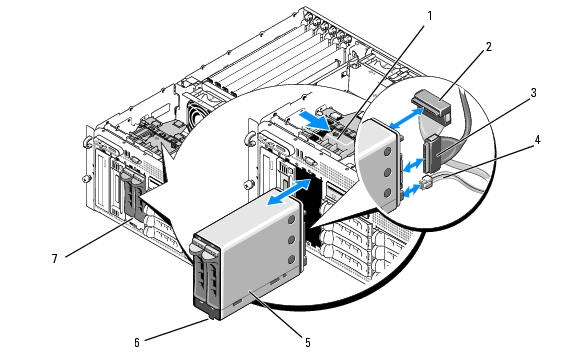
- Push the latch on top of the peripheral bay to the right to release the flex bay bracket and push the
back of the flex bay bracket partially out of the chassis. See Figure 3-26.
- Note the order of SAS cable connections on the flex bay backplane and disconnect the SAS cables.
See Figure 3-26.
- Disconnect the power cable from the flex bay backplane. See Figure 3-26.
- Remove the 1x2 flex bay drive bracket from the chassis bay.
Figure 3-26. Installing and Removing the Flex Bay Drive Bracket
|
1
|
peripheral bay release latch
|
2
|
SAS connector (SAS_B_IN)
|
3
|
SAS connector (SAS_B_OUT)
|
|
4
|
power connector
|
5
|
1x2 flex bay drive bracket
|
6
|
slot key
|
|
7
|
flex bay
|
|
|
|
|
Installing the 1x2 Flex Bay Drive Bracket
|
|
CAUTION: Only trained service technicians are authorized to remove the system cover and access any of the components inside the system. See your Product Information Guide for complete information about safety precautions, working inside the computer, and protecting against electrostatic discharge. |
- Remove the front bezel, if attached. See Removing the Bezel.
- Turn off the system and attached peripherals, and disconnect the system from the electrical outlet and
peripherals.
- Open the system. See Opening the System.
- Remove the flex bay filler panel, if present.
- Insert the 1x2 flex bay bracket three-quarters of the way into the flex bay. See Figure 3-26.
The flex bay bracket is keyed for correct insertion into the flex bay.
- Connect the SAS cables to the flex bay bracket backplane:
- Connect the SAS cable from the SAS_B connector on the 1x8 backplane board to the
SAS_B_OUT connector on the flex bay backplane board. See Figure 6-3 for the location of the
SAS_B connector on the 1x8 backplane board.
- Connect the SAS cable from the SAS RAID controller daughter card to the SAS_B_IN
connector on the flex bay backplane board.
- Connect the power cable to the flex bay backplane board (see Figure 3-26) and to the power
connector on the 1x8 backplane board (see Figure 6-3).
SAS Controller Daughter Card
Your system has a dedicated slot (INT STORAGE) for a SAS controller daughter card. See Figure 3-14. The SAS controller daughter card provides the SAS storage subsystem for your system's internal hard drives.
|
|
NOTE: The non-RAID SAS controller daughter card supports a maximum of four SAS or SATA hard drives. The drives must occupy drive bays 0 through 3. |
The optional SAS RAID controller daughter card supports up to 10 SAS or SATA hard drives and enables you to set up your hard drives in a RAID configuration. For more information, see the documentation that came with your SAS RAID controller daughter card.
Replacing the SAS RAID Controller Daughter Card Battery
- Disconnect the battery cable from the SAS RAID controller daughter card by releasing the tab on the
cable connector on the daughter card and pulling the battery cable free. See Figure 3-27.
- Pull the connector through the routing hole on the expansion-bay bracket and then remove the battery
from the expansion-bay bracket by sliding the battery up out of the battery bay. See Figure 3-27.
- Insert the new battery into the battery bay, ensuring that the battery is aligned and fully seated into the
slots. See Figure 3-27.
- Route the cable connector through the routing hole and connect the storage card battery cable to the
SAS controller daughter card. See Figure 3-27.
Figure 3-27. Replacing a SAS RAID Controller Daughter Card Battery
|
1
|
SAS RAID controller daughter card
|
2
|
RAID battery cable
|
3
|
connector release tab
|
|
4
|
routing hole for RAID battery cable
|
5
|
expansion-bay bracket
|
6
|
battery bay
|
|
7
|
RAID battery
|
|
|
|
|
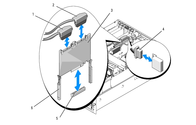
Removing the SAS Controller Daughter Card
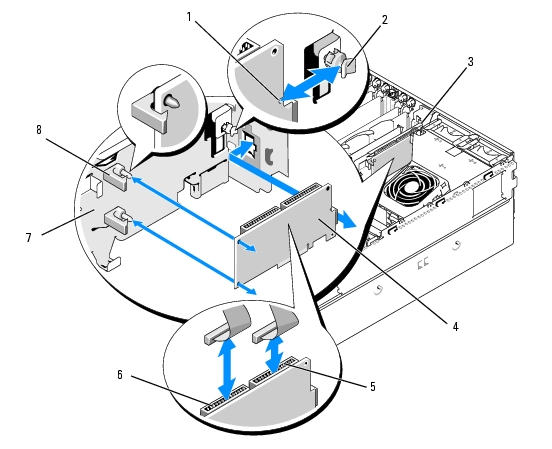
The following procedure applies to either a SAS controller or a SAS RAID controller daughter card. A SAS RAID controller daughter card is illustrated in Figure 3-28.
- If applicable, disconnect the RAID battery cable from the controller card by releasing the tab on the
cable connector on the daughter card and pulling the battery cable free.
- Push outward on the plastic guide rails and gently pull up on the card edges until the card-edge
connector clears the socket on the system board. See Figure 3-28.
- Continue to hold the guide rails outward as you pull the SAS controller daughter card upward from the
rails.
If you need to replace the SAS daughter card battery, see Replacing the SAS RAID Controller Daughter Card Battery.
Figure 3-28. Installing and Removing the SAS Controller Daughter Card
|
1
|
SAS connector 0 (out to 1x8 backplane SAS_A connector)
|
2
|
SAS connector 1 (SAS RAID only) (out to 1x8 backplane SAS_B connector or 1x2 SAS_B_IN connector)
|
3
|
SAS controller daughter card
|
|
4
|
RAID battery cable (SAS RAID only)
|
5
|
daughter card slot socket
|
6
|
slide rails (2)
|
Installing the SAS Controller Daughter Card
The following procedure applies to either a SAS controller or a SAS RAID controller daughter card.
- Hold the daughter card by its edges and align the card with the slide rails on the expansion-bay bracket.
See Figure 3-28.
|
|
NOTE: When pushing the SAS controller daughter card into the socket connector, push only on the card edges and not on the DIMM or any part of the DIMM socket on the daughter card. |
- Insert the card into the slide rails and slide the card down until the card-edge connector seats into the
dedicated storage socket (INT STORAGE) on the system board. See Figure 3-14 and Figure 3-28.
- If present, connect the battery cable to the battery cable connector on the SAS controller daughter
card.
If you need to replace the SAS daughter card battery, see Replacing the SAS RAID Controller Daughter Card Battery.
Cabling the SAS Backplane Boards
Cable Requirements
The cables needed to connect the SAS storage system depend on your configuration. Table 3-2 provides a listing of the available configurations for your SAS storage, the number of cables required, and the number of hard drives supported in each configuration.
Table 3-2. Cable Requirements
|
Configuration
|
Cables Required
|
Hard Drives Supported
|
|---|
SAS controller
| 1
| 4 (bays 0 through 3)
|
SAS RAID controller /no 1x2 flex bay backplane
| 2
| 8 (bays 0 through 7)
|
SAS RAID controller /1x2 flex bay backplane
| 3
| 10 (bays 0 through 9)
|
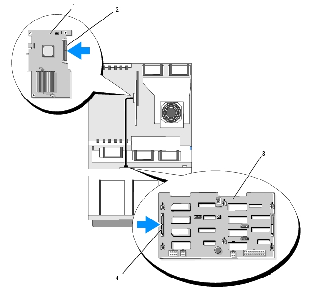
Cabling the SAS Controller (Non-RAID)
For a system with a non-RAID SAS controller daughter card installed, connect SAS_0 on the SAS controller daughter card to connector SAS_A on the SAS backplane board. See Figure 3-29.
Figure 3-29. Cabling the SAS Controller (Non-RAID)
|
1
|
SAS controller daughter card
|
2
|
SAS connector
|
3
|
1x8 SAS backplane
|
|
4
|
SAS_A connector
|
|
|
|
|
Cabling the SAS RAID Controller
For a system with the optional SAS RAID controller daughter card installed, you can configure your system to use the 1x8 SAS backplane only or the 1x8 SAS backplane with the optional 1x2 SAS backplane installed. Cabling for each configuration is discussed in the following subsections. See your SAS RAID controller documentation for details on the different RAID levels supported for your configuration and the drive requirements for specific RAID types.
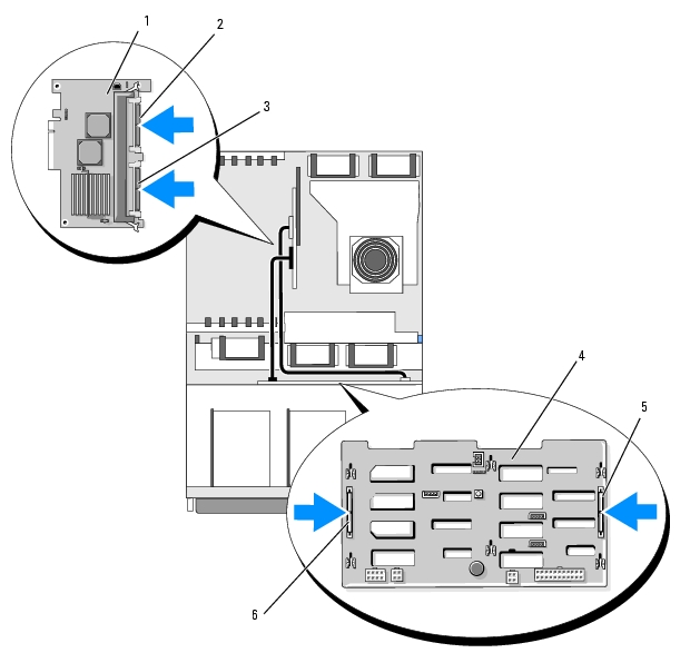
1x8 Drive Configuration
For a 1x8 drive configuration with no optional 1x2 backplane installed in the system, connect SAS_0 on the SAS controller daughter card to connector SAS_A on the 1x8 backplane. Connect SAS_1 on the SAS controller daughter card to connector SAS_B on the 1x8 backplane. See Figure 3-30.
Figure 3-30. Cabling the SAS RAID Controller to the 1x8 Backplane
|
1
|
SAS RAID controller daughter card (DIMM not shown)
|
2
|
SAS_1 connector
|
3
|
SAS_0 connector
|
|
4
|
1x8 SAS backplane
|
5
|
SAS_B connector
|
6
|
SAS_A connector
|
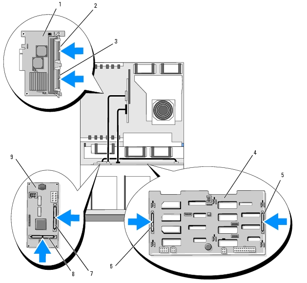
1x8 Plus 1x2 Drive Configuration
If the optional 1x2 SAS backplane is installed in the flex bay, make the following cable connections:
- Connect SAS_0 on the SAS controller daughter card to connector SAS_A on the 1x8 SAS backplane board. See Figure 3-31.
- Connect SAS_1 on the SAS controller daughter card to SAS_B_IN on the 1x2 SAS backplane board. See Figure 3-31.
- Connect SAS_B_OUT on the 1x2 SAS backplane board to connector SAS_B on the 1x8 SAS backplane board. See Figure 3-31.
Figure 3-31. Cabling the SAS RAID Controller to the 1x8 and 1x2 Backplane
|
1
|
SAS RAID controller daughter card (DIMM not shown)
|
2
|
SAS_1 connector (connect to SAS_B_IN connector)
|
3
|
SAS_0 connector (connect to SAS_A connector)
|
|
4
|
1x8 SAS backplane
|
5
|
SAS_B connector
|
6
|
SAS_A connector
|
|
7
|
SAS_B_IN connector
|
8
|
SAS_B_OUT connector (connect to SAS_B connector)
|
9
|
1x2 SAS backplane
|
Configuring the Boot Drive
By default, the system boots from drive 0 on the 1x8 SAS backplane. The order of boot devices is specified in the System Setup program. See Using the System Setup Program.
Control Panel Assembly (Service-Only Procedure)
Removing the Control Panel Assembly
The following procedure applies to either a rack or tower system. Figure 3-32 illustrates a control panel assembly in the rack orientation.
|
|
CAUTION: Only trained service technicians are authorized to remove the system cover and access any of the components inside the system. See your Product Information Guide for complete information about safety precautions, working inside the computer, and protecting against electrostatic discharge. |
- Remove the front bezel, if attached. See Removing the Bezel.
- Turn off the system and attached peripherals, and disconnect the system from the electrical outlet and
peripherals.
- Open the system. See Opening the System.
- If you have a tower system, remove the system top panel:
- Remove the screw on the top back of the system that secures the system top panel.
- Slide the panel back until it clears the chassis hooks and lift up to remove the panel.
- Disconnect the display module cable from the control panel board. See Figure 3-32.
- Remove the three screws that secure the control panel board to the system chassis and remove the
board. See Figure 3-32.
- Disconnect the control panel cable from the back of the control panel. See Figure 3-32.
|
|
NOTICE: Do not pull on the cable to unseat the connector. Doing so can damage the cable. |
- Squeeze the metal tabs on the ends of the cable connector.
- Gently work the connector out of the socket.
- Remove the display module:
- Insert the end of a paper clip into the hole on the right side of the display module and gently
pry the label off.
- Using a T10 Torx driver, remove the two screws that secure the display module to the system
chassis.
- Remove the display module from the chassis cutout.
Figure 3-32. Removing the Control Panel Assembly
|
1
|
display module screws (2)
|
2
|
display module
|
3
|
display module cable
|
|
4
|
control panel board
|
5
|
control panel cable
|
6
|
screws (3)
|
|
7
|
system chassis
|
8
|
display module label
|
|
|
Installing the Control Panel Assembly
The following procedure applies to either a rack or tower system. Figure 3-32 illustrates a control panel assembly in the rack orientation.
- Insert the control panel assembly display module into the chassis cutout and secure with the two Torx
screws.
- Affix the control panel label to the display module.
- Install the control panel board in the system chassis and secure with the three Phillips screws. See
Figure 3-32.
- Connect the display module ribbon cable to the control panel board. See Figure 3-32.
- Connect the control panel interface cable to the control panel board. See Figure 3-32.
- Close the system. See Closing the System.
- If applicable, reinstall the top panel on your tower system:
- Place the top panel on top of the system and offset slightly so that the panel can engage the chassis
hooks.
- Slide the panel forward to closed position.
- Install the retaining screw to the top back of the system.
- Reconnect the system to the power source and turn on the system and attached peripherals.
- Replace the front bezel, if removed.
System Board (Service-Only Procedure)
Removing the System Board
|
|
CAUTION: Only trained service technicians are authorized to remove the system cover and access any of the components inside the system. See your Product Information Guide for complete information about safety precautions, working inside the computer, and protecting against electrostatic discharge. |
|
|
CAUTION: Whenever you need to lift the system, get others to assist you. To avoid injury, do not attempt to lift the system by yourself. |
- Remove the front bezel, if attached. See Removing the Bezel.
- Turn off the system and attached peripherals, and disconnect the system from the electrical outlet.
- Detach all cables from the front and rear of the system
- If the system is a tower system, place it on its side on top of a work surface.
- Open the system. See Opening the System.
- Disconnect any cables attached to expansion cards in the expansion-bay bracket.
- Remove all of the cooling fans. See Removing and Installing a Fan and Removing or Installing the
Cooling Shroud Fan.
- Remove the center and rear fan brackets. See Removing the Center Fan Bracket and Removing the
Back Fan Bracket.
- Remove the memory cooling shroud.
- Remove all expansion cards from the expansion bay. See Removing an Expansion Card.
- Disconnect the SAS controller daughter card from the system board socket connector:
- Push outward on the plastic guide rails and gently pull up on the card edges until the card-edge
connector clears the socket.
- Leave the SAS controller daughter card in the expansion-bay bracket.
- If a RAC card is present in the system, disconnect the RAC cables from the system board. Leave the
RAC card attached to the expansion-bay bracket.
Squeeze the metal tabs on the ends of the RAC cable connector and gently work the connector out of the socket.
- Remove the expansion-bay bracket:
- Pull inward on the latch on the left side of the bracket along the system chassis wall.
- Pull the bracket slightly forward to free the bracket from the chassis tabs and lift the bracket up
and out of the chassis.
- Remove the TOE key, if present. See Figure 6-2.
- Disconnect all cables from the connectors on the front edge of the system board.
|
|
CAUTION: The DIMMs are hot to the touch for some time after the system has been powered down. Allow time for the DIMMs to cool before handling them. Handle the DIMMs by the card edges and avoid touching the DIMM components. |
- Remove the memory modules. See Removing Memory Modules.
- Remove the CPU processor(s). See Replacing a Processor.
- To remove the system board:
- Lift up the blue retention pin and slide the system board toward the front of the system to
disengage the board from the hooks on the chassis. See Figure 3-33.
- Lift the system board out of the system chassis.
Figure 3-33. Removing the System Board
|
1
|
retention pin
|
2
|
system board
|
3
|
chassis hooks
|
Installing the System Board
|
|
CAUTION: Only trained service technicians are authorized to remove the system cover and access any of the components inside the system. See your Product Information Guide for complete information about safety precautions, working inside the computer, and protecting against electrostatic discharge. |
- Unpack the new system board.
- Install the system board.
- Hold the system board by its front edge and the memory module socket ejectors.
- Carefully lower the system board into the chassis with the DIMM-socket side of the board tilted
down slightly to allow room for the board to clear the chassis wall slides. Ensure that the I/O
connectors on the back edge of the board fit underneath the ledge on the inside of the chassis
back panel.
When the board is properly positioned, the tabs on the chassis will fit through the corresponding slots in the system board.
- Slide the system board tray toward the back of the chassis until the retention pin snaps into
place.
- Reinstall the CPU processor(s). See Replacing a Processor.
- Reinstall the memory modules. See Installing Memory Modules.
- Reconnect all cables to the connectors on the front edge of the system board.
- Reinstall the TOE key, if applicable. See Figure 6-2.
- Reinstall the expansion-bay bracket:
- Align the expansion-bay bracket with the tabs on the system board and the chassis wall and
then carefully push the bracket into the tabs.
- Gently push the bracket toward the back of the chassis until the latch on the left side of the
bracket engages.
- Install all expansion cards. See Installing an Expansion Card.
- Reinstall the SAS controller daughter card. See SAS Controller Daughter Card.
- If a RAC card is present, attach the cables to the RAC connectors on the system board. See Installing a
RAC Card.
- Reinstall the center and rear fan brackets. See Replacing the Center Fan Bracket and Replacing the
Back Fan Bracket.
- Install the memory cooling shroud. See Installing the Cooling Shroud.
|
|
NOTICE: Never operate your system with the memory cooling shroud removed. Overheating of the system can develop quickly resulting in a shutdown of the system and the loss of data. |
- Install all of the cooling fans. See Removing and Installing a Fan
- Reconnect all cables to the expansion cards.
- Close the system. See Closing the System.
- Reconnect all cables to the front and rear of the system.
- Reconnect the system to the power source and turn on the system and attached peripherals.
- Replace the front bezel, if removed.
Power Distribution Board (Service-Only Procedure)
Removing the Power Distribution Board
|
|
CAUTION: Only trained service technicians are authorized to remove the system cover and access any of the components inside the system. Before performing any procedure, see your Product Information Guide for complete information about safety precautions, working inside the computer, and protecting against electrostatic discharge. |
|
|
CAUTION: Whenever you need to lift the system, get others to assist you. To avoid injury, do not attempt to lift the system by yourself. |
- Turn off power to the system and disconnect the power cable from the power source.
- Detach all cables from the rear of the system.
- If the system is a tower system, place it on its side on top of a work surface.
- Open the system. See Opening the System.
- Perform all of the additional steps to remove the system board in Removing the System Board.
- Disconnect all cables connecting the system board to the SAS backplane board, the control panel, and
any tape or hard drives in the peripheral or flex bays.
- Disconnect the cables connecting the system board and SAS backplane board to the power
distribution board.
- Unlock the power supplies from the system and slide them back 5 cm (2 inches). See Removing a
Power Supply
- Using a #2 Phillips screwdriver, remove the five screws from the power distribution board. See
Figure 3-34.
- Remove the power distribution board from the system chassis. See Figure 3-34.
Figure 3-34. Removing the Power Distribution Board
|
1
|
power distribution board
|
2
|
screws (5)
|
Installing the Power Distribution Board
|
|
CAUTION: Only trained service technicians are authorized to remove the system cover and access any of the components inside the system. See your Product Information Guide for complete information about safety precautions, working inside the computer, and protecting against electrostatic discharge. |
- Unpack the new power distribution board.
- Holding the power distribution board by its edges, carefully lower the board into the chassis and
align the board with the fastener holes at the bottom of the chassis. See Figure 3-34.
- Using a #2 Phillips screwdriver, install the five screws to secure the power distribution board to the
system chassis. See Figure 3-34.
- Attach the power cables to the power distribution board.
- Reinstall the system board. See Installing the System Board.
- Attach the cables from the power distribution board to the system board.
- Attach the cables from the power distribution board to the SAS backplane board.
- Reconnect all cables from the system board to the SAS backplane board, the control panel, and any
tape or hard drives in the peripheral or flex bays.
- Close the system. See Closing the System.
- Reinsert the power supplies. See Installing a Power Supply.
- Reconnect the system to the peripherals and electrical outlet, and turn on the system.
Back to Contents Page
 Opening and Closing the System