 Opening and Closing the System
Activating the Integrated NIC TOE
Dell™ PowerEdge™ 2950 Systems Hardware Owner's Manual
|
|
|
This section describes how to install the following system components:
You may need the following items to perform the procedures in this section:

|
CAUTION: Only trained service technicians are authorized to remove the system cover and access any of the components inside the system. See your Product Information Guide for complete information about safety precautions, working inside the computer, and protecting against electrostatic discharge. |
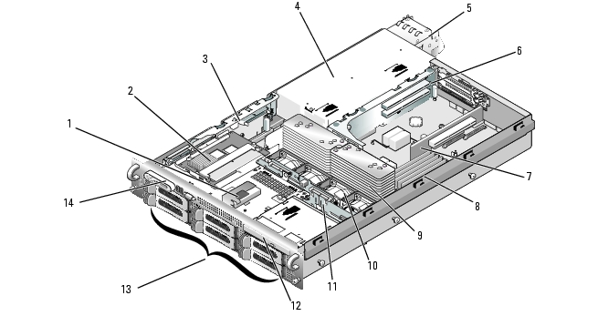
In Figure 3-1, the bezel and system cover are removed to provide an interior view of the system.
|
1 |
RAID battery (optional) |
2 |
SAS controller daughter card or SAS RAID controller daughter card (optional) |
3 |
sideplane |
|
4 |
power supply bay |
5 |
power supplies (2) |
6 |
left riser |
|
7 |
central riser |
8 |
memory modules (8) |
9 |
heatsinks and microprocessors (2) |
|
10 |
hot-pluggable fans (4) |
11 |
SAS backplane |
12 |
slimline optical drive (optional) |
|
13 |
SAS or SATA hard drives (up to 8, depending on configuration) |
14 |
control panel |
|
|
The system board holds the system's control circuitry and other electronic components. Several hardware options, such as the microprocessors and memory, are installed directly on the system board. The expansion-card cage containing the left riser accommodates up to two full-length PCIe or PCI-X expansion cards, while the central riser accommodates one half-length PCIe expansion card.
The system provides space for an optional optical drive. The optical drive connects to the controllers on the system board through the sideplane board. For more information, see Optical Drive.
Depending on the hard drive configuration you ordered, an optional 3.5-inch diskette drive, and an optional tape drive may also be available for installation into a media bay. See Table 3-1 for configuration options.
Table 3-1. Hard Drive and Media Bay Configurations
|
Number of Hard Drives on Backplane |
Hard-Drive Size |
Media Bay |
|---|---|---|
6 | 3.5-inch | No |
4 | 3.5-inch | Yes |
8 | 2.5-inch | Yes |
The hard-drive bays provide space for up to eight 2.5-inch SAS drives or six 3.5-inch SAS or SATA hard drives. The hard drives connect to a RAID controller card through the SAS backplane board. For more information, see Hard Drives and SAS Controller Daughter Card.
During an installation or troubleshooting procedure, you may be required to change a jumper setting. For more information, see System Board Jumpers.
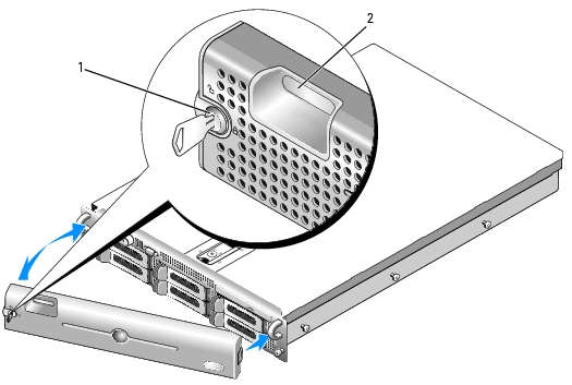
A lock on the bezel restricts access to the power button, diskette drive, optical drive, and hard drive(s). A control panel LCD located on the front panel and accessible through the front bezel displays the system's status.
Figure 3-2. Removing the Front Bezel
|
1 |
bezel lock |
2 |
control panel LCD |
To replace the front bezel, perform the above steps in reverse.
|
|
CAUTION: Only trained service technicians are authorized to remove the system cover and access any of the components inside the system. See your Product Information Guide for complete information about safety precautions, working inside the computer, and protecting against electrostatic discharge. |
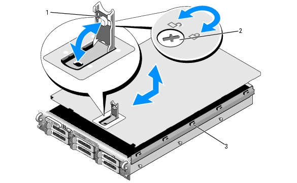
To upgrade or troubleshoot the system, remove the system cover to gain access to internal components.
Figure 3-3. Removing the Cover
|
1 |
latch |
2 |
latch release lock |
3 |
alignment J hooks |
This subsection describes how to install and configure SAS or SATA hard drives in the system's internal hard-drive bays. Your system features up to six 3.5-inch hard drives, or eight 2.5-inch hard drives. All drives connect to the system board through one of three optional SAS backplane boards. See SAS Backplane Board Connectors for information on these backplane options.

|
NOTE: Depending on the hard drive configuration you ordered, your hard drive(s) may come with a drive interposer that allows your SATA drive to attach to the SAS connector on the backplane. |
Hard drives are supplied in special hot-pluggable drive carriers that fit in the hard-drive bays. Depending on your configuration, you received one of the following two drive carrier types:

|
NOTICE: Before attempting to remove or install a drive while the system is running, see the documentation for the optional SAS RAID controller daughter card to ensure that the host adapter is configured correctly to support hot-plug drive removal and insertion. |
|
|
NOTE: It is recommended that you use only drives that have been tested and approved for use with the SAS backplane board. |
You may need to use different programs than those provided with the operating system to partition and format SAS or SATA hard drives.
|
|
NOTICE: Do not turn off or reboot your system while the drive is being formatted. Doing so can cause a drive failure. |
When you format a high-capacity hard drive, allow enough time for the formatting to be completed. Long format times for these drives are normal. A 9-GB hard drive, for example, can take up to 2.5 hours to format.
|
|
NOTICE: To maintain proper system cooling, all empty hard-drive bays must have drive blanks installed. If you remove a hard-drive carrier from the system and do not reinstall it, you must replace the carrier with a drive blank. |
The process for removing a drive blank depends on whether your system is configured with 3.5-inch or 2.5-inch hard drives.
For 3.5-inch hard drive configurations:
For 2.5-inch hard drive configurations, remove the blank as you would the 2.5-inch hard drive carrier:
The process for installing a drive blank depends on whether your system is configured with 3.5-inch or 2.5-inch hard drives.
For 3.5-inch hard drive configurations, the drive blank is keyed to ensure correct insertion into the drive bay. To install a 3.5-inch drive blank, insert and rotate in the keyed side of the blank into the drive bay and press evenly on the other end of the blank until it is fully inserted and latched.
For 2.5-inch hard drive configurations, install the hard drive blank as a 2.5-inch hard drive carrier:
If the drive has been online, the green activity/fault indicator will flash as the drive is powered down. When both drive indicators are off, the drive is ready for removal.
|
|
NOTICE: To maintain proper system cooling, all empty hard-drive bays must have drive blanks installed. |
|
|
NOTICE: When installing a hard drive, ensure that the adjacent drives are fully installed. Inserting a hard-drive carrier and attempting to lock its handle next to a partially installed carrier can damage the partially installed carrier's shield spring and make it unusable. |
|
|
NOTICE: Not all operating systems support hot-plug drive installation. See the documentation supplied with your operating system. |
Figure 3-4. Installing a Hot-Plug Hard Drive

|
1 |
hard drive |
2 |
drive carrier |
3 |
drive carrier release handle |
|
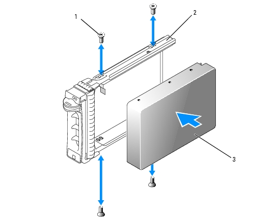
|
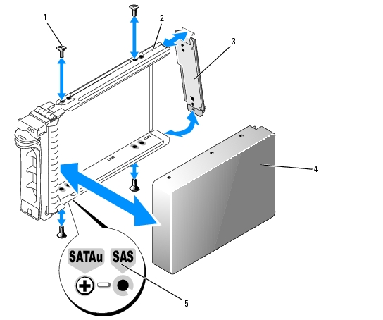
NOTE: SAS hard drives must be installed only in SATAu drive carriers. The SATAu drive carrier is labeled "SATAu" and also has marks indicating the SAS and SATA mounting screws. |
When aligned correctly, the rear of the hard drive will be flush with the rear of the hard-drive carrier.
Figure 3-5. Installing a SAS Hard Drive Into a SATAu Drive Carrier

|
1 |
screws (4) |
2 |
SATAu drive carrier |
3 |
SAS hard drive |
|
|
NOTE: SATA hard drives that connect directly to the SAS backplane must be installed in SATA drive carriers (labeled "SATA"). Only SATA hard drives with interposer cards can be installed in SATAu drive carriers. |
Figure 3-6. Installing a SATA Hard Drive Into a SATA Drive Carrier
|
1 |
screws (4) |
2 |
SATA drive carrier |
3 |
SATA hard drive |
|
|
NOTE: When you install a SATA hard drive into a SATAu drive carrier, you must install an interposer card onto the back of the hard drive. The SATAu drive carrier is labeled "SATAu" and also has marks indicating the SAS and SATA mounting screws. |
When aligned correctly, the rear of the interposer will be flush with the rear of the hard-drive carrier.
Figure 3-7. Installing a SATA Hard Drive and Interposer Card Into a SATAu Drive Carrier
|
1 |
screws (4) |
2 |
SATAu drive carrier |
3 |
interposer card (SATA only) |
|
4 |
SATA hard-drive |
5 |
hole labels |
|
|
Your system supports one or two power supplies rated at an output of 750 W. If only one power supply is installed, it must be installed in the left power supply bay (1). If two power supplies are installed, the second power supply serves as a redundant, hot-plug power source.
|
|
NOTICE: To ensure proper system cooling, the power supply blank must be installed on the unoccupied power supply bay in a non-redundant configuration. See Installing the Power Supply Blank. |
|
|
NOTICE: The system requires one power supply for the system to operate normally. The system is in the redundant mode when two power supplies are installed and both power supplies are connected to an AC power source. Remove and replace only one power supply at a time in a system that is powered on. Operating the system with only one power supply installed and without a power supply blank installed for extended periods of time can cause the system to overheat. |
|
|
NOTICE: If only one power supply is installed, it must be installed in the left power supply bay (1). |
|
|
NOTICE: If you connect the system to a power source in the range of 120 to 220 VAC, and if two power supplies are installed, the second power supply serves as a redundant, hot-plug power source. |
|
|
NOTE: On your rack system, you may have to unlatch and lift the cable management arm if it interferes with power supply removal. For information about the cable management arm, see the system's Rack Installation Guide. |
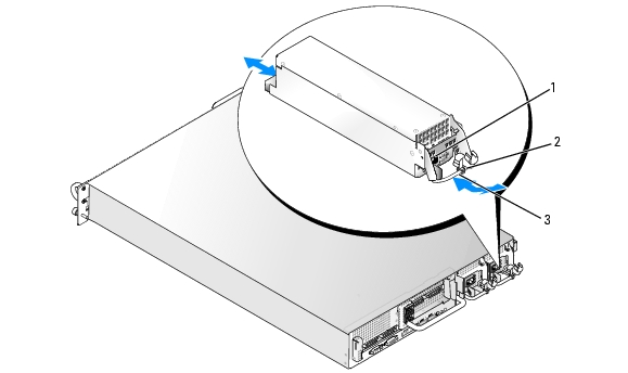
Figure 3-8. Removing and Installing a Power Supply
|
1 |
locking tab |
2 |
cable retention bracket |
3 |
power-supply handle |
|
|
NOTE: After installing a new power supply, allow several seconds for the system to recognize the power supply and determine whether it is working properly. The power supply status indicator will turn green to signify that the power supply is functioning properly. See Figure 1-4. |
Using a Phillips screwdriver, remove the screw on the left side of the blank, rotate the blank slightly to clear the bay, and remove from the chassis.
|
|
NOTICE: To ensure proper system cooling, the power supply blank must be installed on the unoccupied power supply bay in a non-redundant configuration. Remove the power supply blank only if you are installing a second power supply. |
To install the power supply blank, insert the tab on the right edge of the blank into the slot in the power supply bay wall. Rotate the blank into the power supply bay and secure with the Phillips screw.
The system includes four hot-pluggable cooling fans.
|
|
CAUTION: Only trained service technicians are authorized to remove the system cover and access any of the components inside the system. See your Product Information Guide for complete information about safety precautions, working inside the computer, and protecting against electrostatic discharge. |
|
|
NOTICE: The system fans are hot-pluggable. To maintain proper cooling while the system is on, replace only one fan at a time. |
|
|
CAUTION: Use caution when handling the fan until the fan blades stop spinning. |
Figure 3-9. Removing and Installing a Cooling Fan

|
1 |
fan bracket |
2 |
fan handle |
3 |
fan |
The cooling shroud produces and directs airflow over the system memory modules.
|
|
CAUTION: The DIMMs are hot to the touch for some time after the system has been powered down. Allow the DIMMs to cool before handling them. |
|
|
NOTICE: Never operate your system with the memory cooling shroud removed. Overheating of the system can develop quickly resulting in a shutdown of the system and the loss of data. |
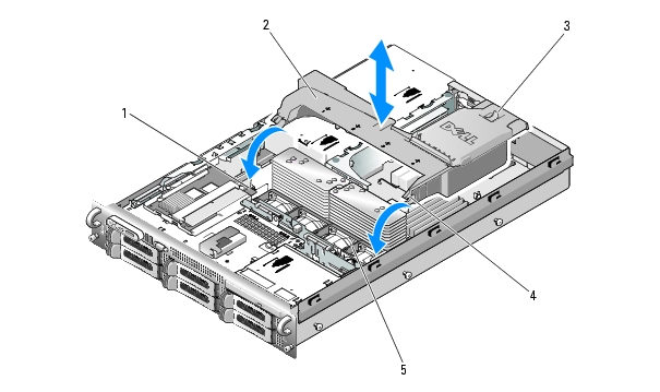
Figure 3-10. Removing and Installing the Cooling Shroud
|
1 |
shroud pivots (2) |
2 |
cooling shroud |
3 |
release latch |
|
4 |
shroud hinges (2) |
5 |
fan bracket |
|
|
|
|
CAUTION: Only trained service technicians are authorized to remove the system cover and access any of the components inside the system. See your Product Information Guide for complete information about safety precautions, working inside the computer, and protecting against electrostatic discharge. |
If the bracket does not disengage completely, push down slightly on the bracket when releasing the latch.
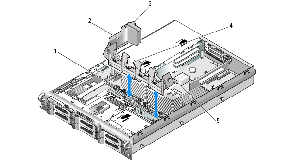
Figure 3-11. Removing and Installing the Fan Bracket
|
1 |
release latch |
2 |
fan bracket |
3 |
plastic clip |
|
4 |
fan bracket slot in power supply cage |
5 |
tabs (2) |
|
|
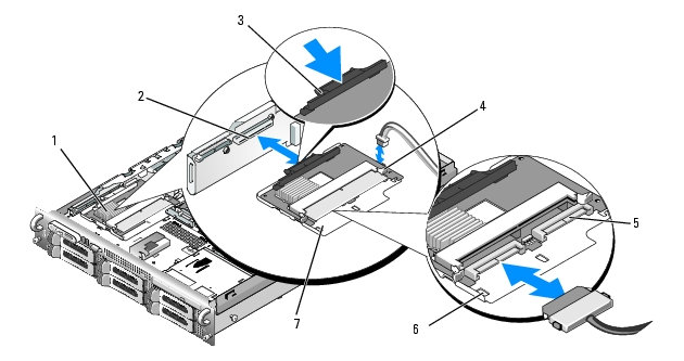
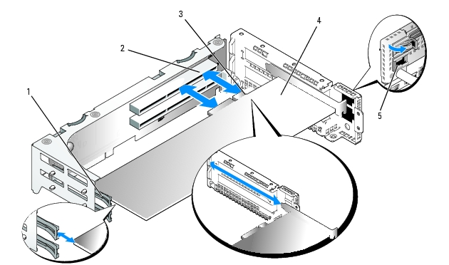
Your system includes a dedicated slot on the sideplane for a SAS controller daughter card. The SAS controller daughter card provides the SAS storage subsystem for your system's internal hard drives. The optional SAS RAID controller daughter card allows you to set up any internal hard drives in a RAID configuration. Although the cabling for the two types of daughter cards is different (the SAS controller daughter card has only one connector, while the SAS RAID controller daughter card has two), both cards install into the sideplane as described below. The SAS RAID controller daughter card is shown in Figure 3-12.
|
|
NOTICE: Do not press on the RAID card DIMM while installing the RAID card into the sideplane board. |
|
|
NOTE: If you are installing a replacement RAID card, do not remove the plastic cover protecting the card until after installation of the card is complete. |
Ensure that the card is aligned with the mid-section standoff on the SAS controller daughter card and fully seat the card in the sideplane board.
Figure 3-12. Installing a SAS Controller Daughter Card
|
1 |
SAS controller daughter card |
2 |
SAS controller daughter card slot |
3 |
release tab |
|
4 |
SAS controller daughter card battery connector |
5 |
SAS connectors 0 and 1 (for RAID card only) out to backplane SAS_A or SAS_B (for RAID card only) connector |
6 |
chassis slots (2) |
|
7 |
SAS controller daughter card tray |
|
|
|
|
Figure 3-13. SAS Controller Daughter Card Cabling With all Backplanes
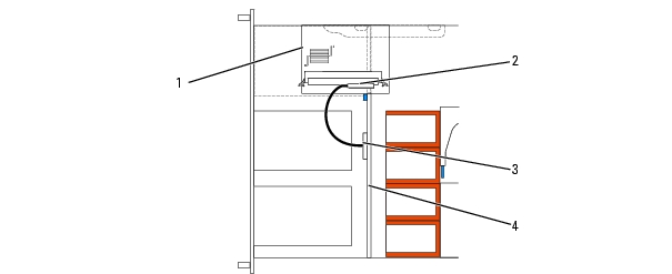
1 SAS controller daughter card 2 SAS controller 0 3 SAS backplane A 4 backplane
Figure 3-14. SAS RAID Controller Daughter Card Cabling With 3.5-inch x6 Backplane
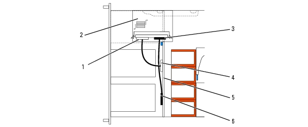
1 SAS controller 0 2 SAS RAID controller daughter card 3 SAS controller 1 4 SAS backplane A 5 3.5-inch x6 backplane 6 SAS backplane B
Figure 3-15. SAS RAID Controller Daughter Card Cabling With 3.5-inch x4 Backplane
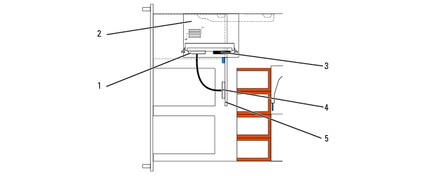
1 SAS controller 0 2 SAS RAID controller daughter card 3 SAS controller 1 4 SAS backplane A 5 3.5-inch x4 backplane
Figure 3-16. SAS RAID Controller Daughter Card Cabling With 2.5-inch x8 Backplane
1 SAS controller 0 2 SAS RAID controller daughter card 3 SAS backplane A 4 SAS controller 1 5 SAS backplane B 6 2.5-inch x8 backplane
Figure 3-17. Installing a RAID Battery
|
1 |
chassis battery carrier slot (2) |
2 |
battery cable |
3 |
battery carrier |
|
4 |
SAS RAID controller daughter card battery |
|
|
|
|
|
|
NOTE: System boot is not supported from an external device attached to a SAS or SCSI adapter. See support.dell.com for the latest support information about booting from external devices. |
If you plan to boot the system from a hard drive, the drive must be attached to the primary (or boot) controller. The device that the system boots from is determined by the boot order specified in the System Setup program.
The System Setup program provides options that the system uses to scan for installed boot devices. See Using the System Setup Program for information about the System Setup program.
The system is available with either a PCI-X or a PCI Express (PCIe) left riser board option. The PCI-X left riser board provides two PCI-X 64-bit/133-MHz expansion slots, while the PCIe left riser board provides one PCIe x8-lane expansion slot and one PCIe x4-lane expansion slot. The half-height center riser board provided with both PCI-X and PCIe left riser board options features one PCIe x8-lane expansion slot. The three expansion card slots are on separate buses.
To identify expansion slots, see Expansion-Card Riser-Board Components and PCI Buses.
|
|
NOTE: The expansion-card slots are not hot-pluggable. |
|
|
NOTE: Although the PCIe x4-lane expansion slot on the PCIe left riser option is physically a PCIe x8 connector, it functions only as a PCIe x4-lane slot. |
|
|
NOTE: Slot 1 on the central riser supports half-length expansion cards only. Slots 2 and 3 on the left riser support full-length expansion cards. |
|
|
NOTE: Your system supports up to two RAID expansion cards to manage external storage. |
|
|
CAUTION: Only trained service technicians are authorized to remove the system cover and access any of the components inside the system. See your Product Information Guide for complete information about safety precautions, working inside the computer, and protecting against electrostatic discharge. |
|
|
NOTE: The procedure for installing expansion cards into the left and central risers is the same except that there is no card guide for cards installing into the central riser, and only half-height cards are supported on the central riser. Full-length expansion card installation is illustrated in Figure 3-18. |
For instructions, see the documentation accompanying the card.
Figure 3-18. Installing an Expansion Card
|
1 |
front card guide |
2 |
expansion-card connector |
3 |
card-edge connector |
|
4 |
expansion card |
5 |
expansion-card guide latch |
|
|
See the documentation that came with the card for information about its cable connections.
|
|
CAUTION: Only trained service technicians are authorized to remove the system cover and access any of the components inside the system. See your Product Information Guide for complete information about safety precautions, working inside the computer, and protecting against electrostatic discharge. |
|
|
NOTE: You must install a filler bracket over an empty expansion slot to maintain Federal Communications Commission (FCC) certification of the system. The brackets also keep dust and dirt out of the system and aid in proper cooling and airflow inside the system. |
|
|
CAUTION: Only trained service technicians are authorized to remove the system cover and access any of the components inside the system. See your Product Information Guide for complete information about safety precautions, working inside the computer, and protecting against electrostatic discharge. |
|
|
NOTE: You must remove all expansion cards from the expansion-card cage before removing the expansion-card cage from the system. |
Figure 3-19. Installing and Removing the Expansion-Card Cage
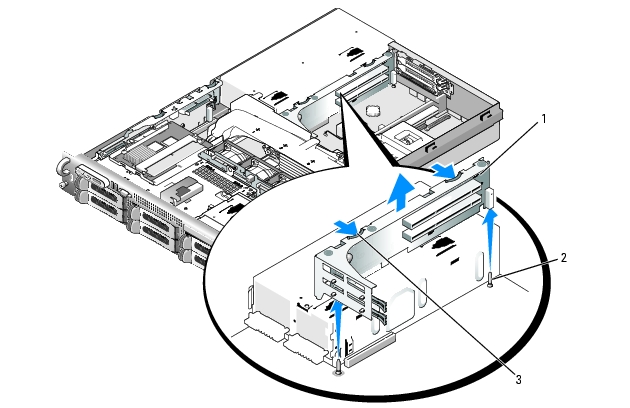
|
1 |
expansion-card cage |
2 |
chassis pins (2) |
3 |
release latches (2) |
|
|
CAUTION: Only trained service technicians are authorized to remove the system cover and access any of the components inside the system. See your Product Information Guide for complete information about safety precautions, working inside the computer, and protecting against electrostatic discharge. |
|
|
CAUTION: Only trained service technicians are authorized to remove the system cover and access any of the components inside the system. See your Product Information Guide for complete information about safety precautions, working inside the computer, and protecting against electrostatic discharge. |
The optional Remote Access Controller (RAC) provides a set of advanced features for managing the server remotely. The following procedure describes the steps for installing the optional RAC card.
Figure 3-20. Installing a RAC Card
|
1 |
RAC-card connectors (2) |
2 |
RAC-card cables (2) |
3 |
retention standoff hole |
|
4 |
RAC card |
5 |
filler plug |
6 |
support standoffs holes(2) |
When the front of the card is fully seated, the plastic standoff snaps over the edge of the card.
|
|
NOTICE: Be careful when attaching cables to the system board that you do not damage the surrounding system board components. |
|
|
NOTICE: When detaching the RAC cables from the system board, squeeze the metal ends of the cable connectors and gently work the connector out of the socket. Do not pull on the cable to unseat the connector. Doing so can damage the cable. |
See the RAC card documentation for information on configuring and using the RAC card.
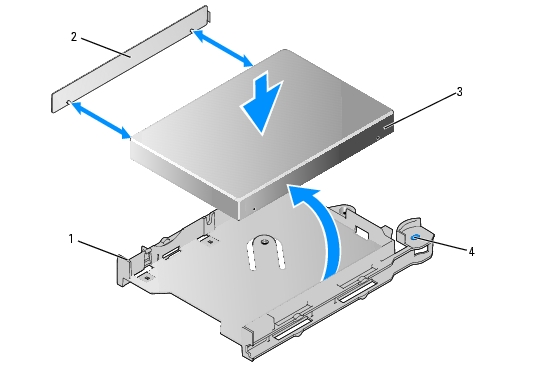
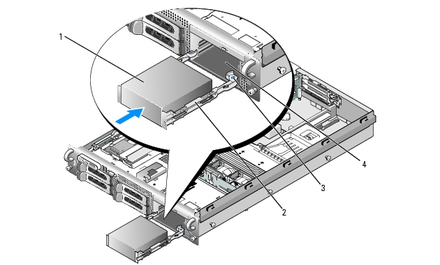
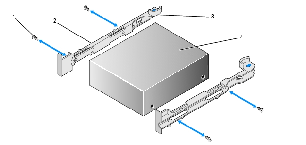
An optional slimline optical drive is mounted on a tray that slides in the front panel and connects to the controllers on the system board through the SAS backplane board.
|
|
CAUTION: Only trained service technicians are authorized to remove the system cover and access any of the components inside the system. See your Product Information Guide for complete information about safety precautions, working inside the computer, and protecting against electrostatic discharge. |
Figure 3-21. Removing and Installing the Optical Drive Tray
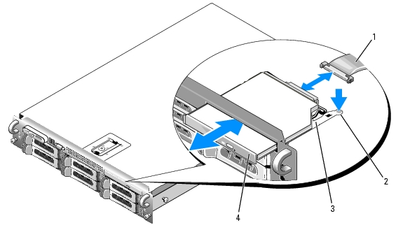
|
1 |
optical-drive cable |
2 |
optical-drive release tab |
3 |
optical -drive tray |
|
4 |
optical drive |
|
|
|
|
The optical drive opening is above the hard-drive slots on the far right, or the flex bay, depending on your system's drive configuration (the hard-drives slots are identified by labels on the front panel of the system).
|
|
CAUTION: Only trained service technicians are authorized to remove the system cover and access any of the components inside the system. See your Product Information Guide for complete information about safety precautions, working inside the computer, and protecting against electrostatic discharge. |
Figure 3-22. Installing and Removing the Diskette Drive From the System
|
1 |
diskette drive carrier |
2 |
release tabs (2) |
3 |
media bay |
|
|
CAUTION: Only trained service technicians are authorized to remove the system cover and access any of the components inside the system. See your Product Information Guide for complete information about safety precautions, working inside the computer, and protecting against electrostatic discharge. |
Figure 3-23. Installing and Removing the Diskette Drive Into and From the Drive Carrier
|
1 |
diskette drive tray |
2 |
shim |
3 |
diskette drive |
|
4 |
diskette drive release tabs (2) |
|
|
|
|
This section describes how to configure and install an internal SCSI tape drive.
|
|
NOTE: Installing a SCSI tape drive requires an optional SCSI controller card. |
|
|
NOTICE: See "Protecting Against Electrostatic Discharge" in the safety instructions in your Product Information Guide. |
Figure 3-24. Removing and Installing the Tape Drive Carrier
|
1 |
tape drive blank |
2 |
tape drive rails |
3 |
release tab (2) |
|
4 |
media bay |
|
|
|
|
Ground yourself by touching an unpainted metal surface on the back of the system, unpack the drive (and controller card, if applicable), and compare the jumper and switch settings with those in the drive documentation.
Figure 3-25. Removing and Installing an Internal SCSI Tape Drive
|
1 |
screws (4) |
2 |
tape drive rails (2) |
3 |
rail release tabs (2) |
|
4 |
tape drive |
|
|
|
|
The optional tape drive available with the 3.5" x4 and 2.5" x8 backplane configurations connects to the system board through an expansion card plugged into one of the PCI expansion card slots. The tape drive cable is routed along the right side of the chassis and behind the tape drive cable retention bracket.
To remove the tape drive cable retention bracket, gently draw the blue release latch toward the center of the system while sliding the cable retention bracket toward the front of the system and disengaging the bracket from the chassis wall. See Figure 3-26.
To replace the bracket, align the bracket clips with their slots on the chassis wall, then slide the bracket toward the back of the system until all the clips and the blue release latch are fully engaged.
Figure 3-26. Installing and Removing the Tape Drive Cable Retention Bracket
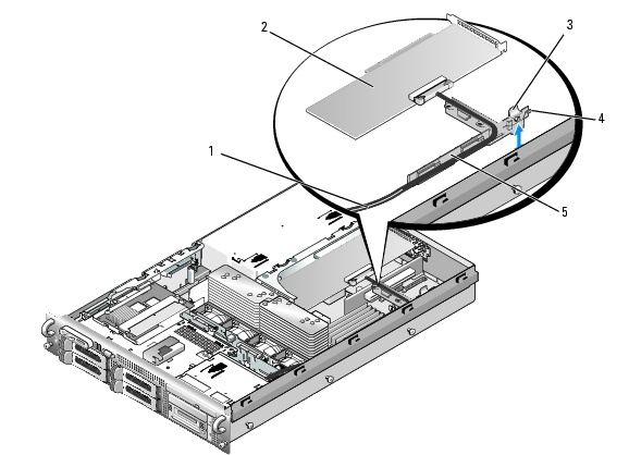
|
1 |
tape drive cable |
2 |
SCSI controller card |
3 |
release latch |
|
4 |
bracket clips (6) |
5 |
tape drive cable retention bracket |
|
|
You can upgrade your system memory to a maximum of 32 GB by installing 533MHz or 667MHz fully buffered (FB) DDR II memory modules in sets of 256-MB, 512-MB, 1-GB, 2-GB, or 4-GB. The eight memory sockets are located on the system board under the cooling shroud adjacent to the power supply bays. See Figure 6-2. You can purchase memory upgrade kits from Dell.
|
|
NOTICE: If you remove your original memory modules from the system during a memory upgrade, keep them separate from any new memory modules that you may have, even if you purchased the new memory modules from Dell. Use only 533 MHz or 667 MHz DDR II FB-DIMMs. |
The memory module sockets are divided into two equal branches (0 and 1). Each branch consists of two channels:
Each channel consists of two DIMM sockets:
The first DIMM socket of each channel has white release tabs.
To ensure optimal performance of your system, observe the following guidelines when configuring your system memory.
System performance can be affected if your memory configuration does not conform to the preceding installation guidelines. Your system may issue an error message during startup stating that your memory configuration is non-optimal.
The system supports memory sparing if eight identical memory modules are installed in the system. The memory sparing feature must be enabled in the System Setup program and can be used only if memory mirroring is not enabled.
Memory sparing allocates four ranks of DIMM memory to the spare bank. These four ranks consist of the first rank of memory in DIMM sockets 1 through 4. For single-rank DIMMs, the entire capacity of the four DIMMs is allocated to sparing whereas for dual-rank DIMMs, only half of the four-DIMM capacity is allocated to sparing. Table 3-2 shows how memory sparing splits the available and spared memory in each of the single- and dual-ranked memory module combinations.
Table 3-2. Memory Sparing Configurations
The system supports memory mirroring if eight identical memory modules are installed in the system. Mirroring must be enabled in the System Setup program and can be used only if memory sparing is not enabled. In a mirrored configuration, the total available system memory is one-half of the total installed memory.
|
|
CAUTION: Only trained service technicians are authorized to remove the system cover and access any of the components inside the system. See your Product Information Guide for complete information about safety precautions, working inside the computer, and protecting against electrostatic discharge. |
|
|
NOTICE: Never remove the memory cooling shroud without first powering down the system. Overheating of the system can develop quickly resulting in a shutdown of the system and the loss of data. |
|
|
CAUTION: The DIMMs are hot to the touch for some time after the system has been powered down. Allow time for the DIMMs to cool before handling them. Handle the DIMMs by the card edges and avoid touching the DIMM components. |
Figure 3-27. Installing and Removing a Memory Module
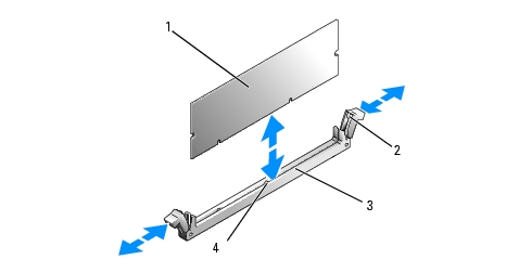
|
1 |
memory module |
2 |
memory module socket ejectors (2) |
3 |
socket |
|
4 |
alignment key |
|
|
|
|
|
|
NOTE: The memory module socket has an alignment key that allows you to install the memory module in the socket in only one way. |
When the memory module is properly seated in the socket, the ejectors on the memory module socket align with the ejectors on the other sockets that have memory modules installed.
|
|
NOTICE: Never operate your system with the memory cooling shroud removed. Overheating of the system can develop quickly resulting in a shutdown of the system and the loss of data. |
The system should have already changed the value to reflect the newly installed memory.
|
|
CAUTION: Only trained service technicians are authorized to remove the system cover and access any of the components inside the system. See your Product Information Guide for complete information about safety precautions, working inside the computer, and protecting against electrostatic discharge. |
|
|
NOTICE: Never remove the memory cooling shroud without first powering down the system. Overheating of the system can develop quickly resulting in a shutdown of the system and the loss of data. |
|
|
CAUTION: The DIMMs are hot to the touch for some time after the system has been powered down. Allow the DIMMs to cool before handling them. Handle the DIMMs by the card edges, and avoid touching the DIMM components. |
|
|
NOTICE: Never operate your system with the memory cooling shroud removed. Overheating of the system can develop quickly resulting in a shutdown of the system and the loss of data. |
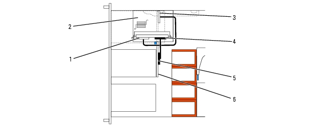
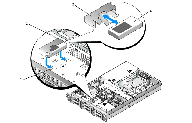
To add TCP/IP Offload Engine (TOE) functionality to the system's integrated NIC, install the TOE NIC hardware key in the TOE_KEY socket on the system board (see Figure 6-2.)
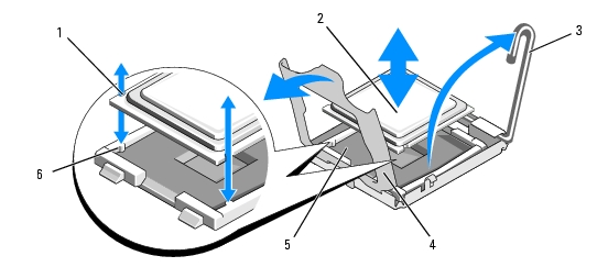
You can upgrade your processor(s) to take advantage of future options in speed and functionality. Each processor and its associated internal cache memory are contained in a land grid array (LGA) package that is installed in a ZIF socket on the system board.
|
|
CAUTION: Only trained service technicians are authorized to remove the system cover and access any of the components inside the system. See your Product Information Guide for complete information about safety precautions, working inside the computer, and protecting against electrostatic discharge. |
|
|
NOTICE: When you remove the heat sink, the possibility exists that the processor might adhere to the heat sink and be removed from the socket. It is recommended that you remove the heat sink while the processor is still warm. |
|
|
NOTICE: Never remove the heat sink from a processor unless you intend to remove the processor. The heat sink is necessary to maintain proper thermal conditions. |
Figure 3-28. Installing and Removing the Heat Sink
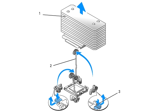
|
1 |
heat sink |
2 |
heat-sink retention levers (2) |
3 |
retention lever latch |
Figure 3-29. Installing and Removing a Processor
|
1 |
notch in processor (2) |
2 |
processor |
3 |
socket-release lever |
|
4 |
processor shield |
5 |
ZIF socket |
6 |
socket key (2) |
|
|
NOTICE: Be careful not to bend any of the pins on the ZIF socket when removing the processor. Bending the pins can permanently damage the system board. |
|
|
NOTICE: Positioning the processor incorrectly can permanently damage the system board or the processor when you turn it on. When placing the processor in the socket, be careful not to bend the pins in the socket. |
|
|
NOTICE: Do not use force to seat the processor. When the processor is positioned correctly, it engages easily into the socket. |
|
|
NOTE: If you did not receive a replacement heat sink, use the heat sink that you removed in step 10. |
If you did not receive a replacement heat sink with your processor kit, do the following:
As the system boots, it detects the presence of the new processor and automatically changes the system configuration information in the System Setup program.
See Running the System Diagnostics for information about running the diagnostics.
The system battery is a 3.0-volt (V), coin-cell battery.
|
|
CAUTION: Only trained service technicians are authorized to remove the system cover and access any of the components inside the system. See your Product Information Guide for complete information about safety precautions, working inside the computer, and protecting against electrostatic discharge. |
|
|
CAUTION: There is a danger of a new battery exploding if it is incorrectly installed. Replace the battery only with the same or equivalent type recommended by the manufacturer. Discard used batteries according to the manufacturer's instructions. See your System Information Guide for additional information. |
|
|
NOTICE: If you pry the battery out of its socket with a blunt object, be careful not to touch the system board with the object. Ensure that the object is inserted between the battery and the socket before you attempt to pry out the battery. Otherwise, you may damage the system board by prying off the socket or by breaking circuit traces on the system board. |
|
|
NOTICE: To avoid damage to the battery connector, you must firmly support the connector while installing or removing a battery. |
Figure 3-30. Replacing the System Battery
|
1 |
positive side of battery connector |
2 |
system battery |
3 |
negative side of battery connector |
|
|
NOTICE: To avoid damage to the battery connector, you must firmly support the connector while installing or removing a battery. |
|
|
CAUTION: Only trained service technicians are authorized to remove the system cover and access any of the components inside the system. See your Product Information Guide for complete information about safety precautions, working inside the computer, and protecting against electrostatic discharge. |
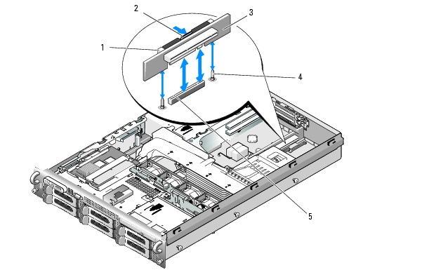
Figure 3-31. Replacing the Left Riser Board
|
1 |
riser release pin |
2 |
expansion-card rails |
3 |
expansion-card cage |
|
4 |
riser securing tabs (6) |
5 |
riser securing slots (6) |
|
|
|
|
CAUTION: Only trained service technicians are authorized to remove the system cover and access any of the components inside the system. See your Product Information Guide for complete information about safety precautions, working inside the computer, and protecting against electrostatic discharge. |
|
|
CAUTION: Only trained service technicians are authorized to remove the system cover and access any of the components inside the system. See your Product Information Guide for complete information about safety precautions, working inside the computer, and protecting against electrostatic discharge. |
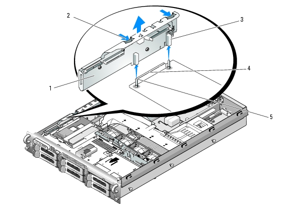
Figure 3-32. Replacing the Central Riser Board
|
1 |
card guide (2) |
2 |
release tab |
3 |
central riser board |
|
4 |
guide pins (2) |
5 |
system board socket |
|
|
|
|
CAUTION: Only trained service technicians are authorized to remove the system cover and access any of the components inside the system. See your Product Information Guide for complete information about safety precautions, working inside the computer, and protecting against electrostatic discharge. |
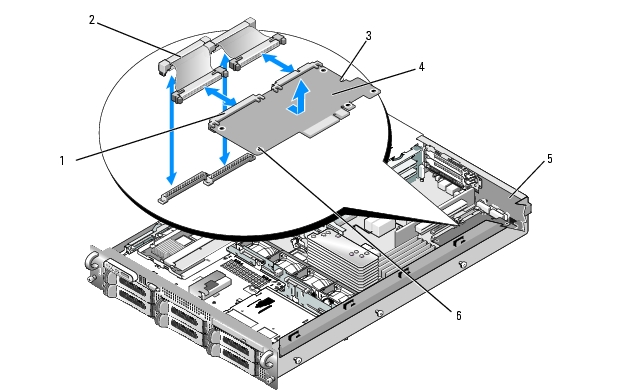
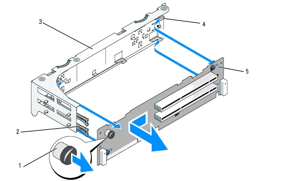
Figure 3-33. Sideplane Removal and Installation
|
1 |
sideplane board |
2 |
sideplane release tabs (2) |
3 |
guides (2) |
|
4 |
backplane connector |
5 |
pins (2) |
|
|
|
|
CAUTION: Only trained service technicians are authorized to remove the system cover and access any of the components inside the system. See your Product Information Guide for complete information about safety precautions, working inside the computer, and protecting against electrostatic discharge. |
|
|
NOTE: To properly reinstall the hard drives, ensure that you record which hard drive you remove from which bay. |
Figure 3-34. SAS Backplane Board Removal
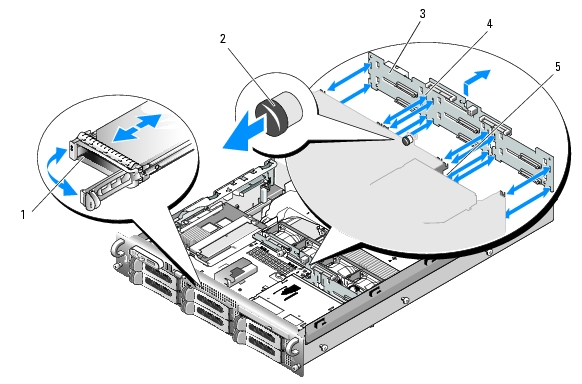
|
1 |
drive carrier |
2 |
SAS-backplane board release pin |
3 |
SAS backplane board |
|
4 |
securing slots (10) |
5 |
securing tabs (10) |
|
|
|
|
CAUTION: Only trained service technicians are authorized to remove the system cover and access any of the components inside the system. See your Product Information Guide for complete information about safety precautions, working inside the computer, and protecting against electrostatic discharge. |
|
|
NOTE: Reinstall the hard drives in the same drive bays from which they were removed. |
|
|
NOTE: The control panel assembly consists of two separate modules—the display module and the control panel circuit board. Use the following instructions to remove and install either module. |
|
|
CAUTION: Only trained service technicians are authorized to remove the system cover and access any of the components inside the system. See your Product Information Guide for complete information about safety precautions, working inside the computer, and protecting against electrostatic discharge. |
|
|
NOTICE: Do not pull on the cable to unseat the connector. Doing so can damage the cable. |
Figure 3-35. Control Panel Removal
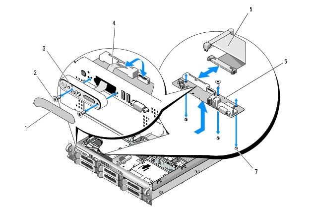
|
1 |
display module label |
2 |
display module securing screws (2) |
3 |
display module |
|
4 |
display module cable |
5 |
control panel cable |
6 |
control panel circuit board |
|
7 |
control-panel circuit board securing screws (3) |
|
|
|
|
|
|
CAUTION: Only trained service technicians are authorized to remove the system cover and access any of the components inside the system. See your Product Information Guide for complete information about safety precautions, working inside the computer, and protecting against electrostatic discharge. |
|
|
CAUTION: The DIMMs are hot to the touch for some time after the system has been powered down. Allow time for the DIMMs to cool before handling them. Handle the DIMMs by the card edges and avoid touching the DIMM components. |
|
|
NOTE: While removing the memory modules, record the memory module socket locations to ensure proper installation. |
Figure 3-36. System Board Removal
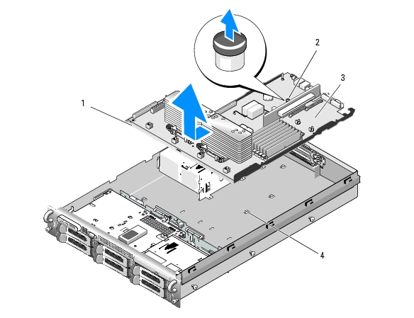
|
1 |
system-board tray |
2 |
system-board tray riser release pin |
3 |
system board |
|
4 |
system-board securing tabs |
|
|
|
|
|
|
CAUTION: Only trained service technicians are authorized to remove the system cover and access any of the components inside the system. See your Product Information Guide for complete information about safety precautions, working inside the computer, and protecting against electrostatic discharge. |