 System Board Jumpers
Dell™ PowerEdge™ 2950 Systems Hardware Owner's Manual
SAS Backplane Board Connectors
Expansion-Card Riser-Board Components and PCI Buses
Disabling a Forgotten Password
This section provides specific information about the system jumpers and describes the connectors on the various boards in the system.
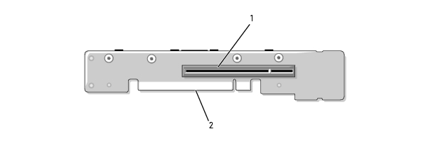
Figure 6-1 shows the location of the configuration jumpers on the system board. Table 6-1 lists the jumper settings.

|
NOTE: To access the jumpers, remove the cooling shroud by lifting the release latch and sliding the shroud towards the front of the system. See Figure 3-10. |
|
|
NOTE: Lift up the memory module airflow shroud for easy access to the jumpers. |
Figure 6-1. System Board Jumpers
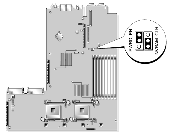
Table 6-1. System Board Jumper Settings
|
|
Jumper |
Setting |
Description |
|---|---|---|---|
|
1 |
PWRD_EN |
|
The password feature is enabled. |
|
|
|
The password feature is disabled. | |
|
2 |
NVRAM_CLR |
|
The configuration settings are retained at system boot. |
|
|
|
The configuration settings are cleared at the next system boot. (If the configuration settings become corrupted to the point where the system will not boot, install the jumper and boot the system. Remove the jumper before restoring the configuration information.) | |
|
NOTE: For the full name of an abbreviation or acronym used in this table, see the Glossary. | |||
See Figure 6-2 and Table 6-2 for the location and description of system board connectors.
Figure 6-2. System Board Connectors
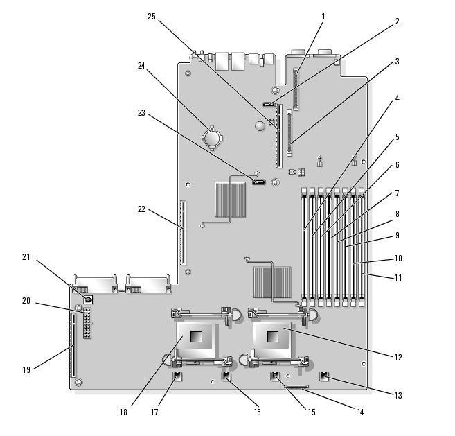
Table 6-2. System Board Connectors
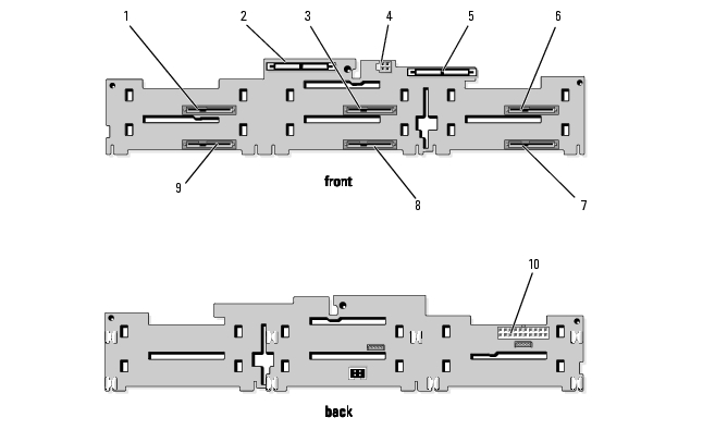
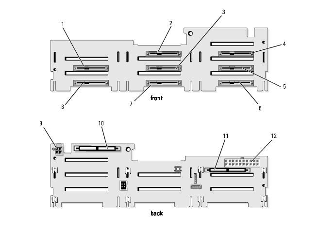
Figure 6-3, Figure 6-4, and Figure 6-5 show the location of the connectors on the three SAS backplane board options.
Figure 6-3. SAS Backplane Board Components: 3.5-inch x6 Option
|
1 |
drive 0 (SASDRV0) |
2 |
primary SAS (SAS_A) |
3 |
drive 2 (SASDRV2) |
|
4 |
optical drive power (CD_PWR) |
5 |
secondary SAS (SAS_B) |
6 |
drive 4 (SASDRV4) |
|
7 |
drive 5 (SASDRV5) |
8 |
drive 3 (SASDRV3) |
9 |
drive 1 (SASDRV1) |
|
10 |
backplane power (BP_PWR) |
|
|
|
|
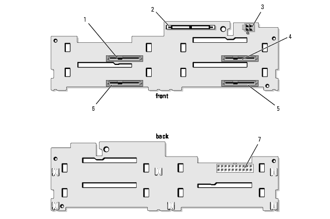
Figure 6-4. SAS Backplane Board Components: 3.5-inch x4 Option
|
1 |
drive 0 (SASDRV0) |
2 |
SAS (SAS_A) |
3 |
tape drive power connector (J_TBU_PWR) |
|
4 |
drive 2 (SASDRV2) |
5 |
drive 3 (SASDRV3) |
6 |
drive 1 (SASDRV1) |
|
7 |
backplane power (J_BP_PWR) |
|
|
|
|
Figure 6-5. SAS Backplane Board Components: 2.5-inch x8 Option
|
1 |
drive 0 (SASDRV0) |
2 |
drive 2 (SASDRV2) |
3 |
drive 3 (SASDRV3) |
|
4 |
drive 5 (SASDRV5) |
5 |
drive 6 (SASDRV5) |
6 |
drive 7 (SASDRV4) |
|
7 |
drive 4 (SASDRV5) |
8 |
drive 1 (SASDRV5) |
9 |
optical drive power (CD_PWR) |
|
10 |
secondary SAS (SAS_B) |
11 |
primary SAS (SAS_A) |
12 |
backplane power (BP_PWR) |
See Figure 6-6 for the location and description of connectors on the sideplane board.
Figure 6-6. Sideplane Board Connectors
|
1 |
control panel (CTRL) |
2 |
SAS controller daughter card (PCIE_STORAGE) |
3 |
chassis intrusion switch |
|
4 |
CD IDE (IDE) |
5 |
pin guides (2) |
6 |
system board connector |
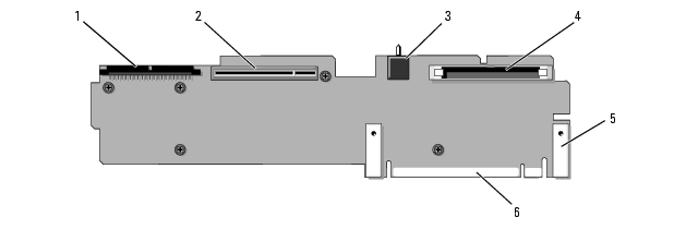
Figure 6-7, Figure 6-8, and Figure 6-9 show the components on the optional PCI-X/PCIe expansion-card riser boards, including the expansion-card slots and buses.
Figure 6-7. Optional PCIe Left Expansion-Card Riser Board Components
|
1 |
riser release pin |
2 |
slot 2 PCIe x8 lane width |
3 |
slot 3 PCIe x4 lane width |
|
4 |
pin guide (2) |
5 |
system board connector |
|
|
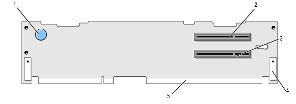
Figure 6-8. Optional PCI-X Left Expansion-Card Riser Board Components
|
1 |
riser release pin |
2 |
slot 2 PCI-X 133-MHz |
3 |
slot 3 PCI-X 133-MHz |
|
4 |
pin guide (2) |
5 |
system board connector |
|
|
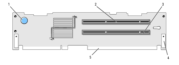
Figure 6-9. Optional PCIe Expansion-Card Central Riser Board Components
|
1 |
slot 1 PCI-X - x8 lane width |
2 |
system board connector |
The system's software security features include a system password and a setup password, which are discussed in detail in Using the System Setup Program. The password jumper enables these password features or disables them and clears any password(s) currently in use.

|
NOTICE: See "Protecting Against Electrostatic Discharge" in the safety instructions in your Product Information Guide. |
See Figure 6-1 to locate the password jumper (labeled "PWRD_EN") on the system board.
The existing passwords are not disabled (erased) until the system boots with the password jumper plug removed. However, before you assign a new system and/or setup password, you must install the jumper plug.
|
|
NOTE: If you assign a new system and/or setup password with the jumper plug still removed, the system disables the new password(s) the next time it boots. |
To assign a new password using the System Setup program, see Assigning a System Password.