Back to Contents Page
System Overview
Dell™ PowerEdge™ 400SC Systems
User's Guide
 Front-Panel Features and Indicators
Back-Panel Features
System Features
Supported Operating Systems
Power Protection Devices
Other Documents You May Need
Obtaining Technical Assistance
This section describes the major hardware and software features of your system and provides information about the indicators on the system's front and back panels. It also provides information about other documents you may need when setting up your system and how to obtain technical assistance.
Front-Panel Features and Indicators
Figure 1-1 shows the front-panel features and indicators of the system. Table 1-1 describes these features and indicators.
Figure 1-1. Front-Panel Features and Indicators
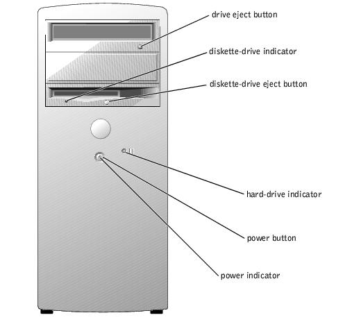
Table 1-1. Front-Panel Features and Indicators
|
Indicator or Feature
|
Description
|
|---|
Diskette-drive indicator | Flashes when the diskette drive is reading or writing data to a diskette. |
Hard-drive indicator | Flashes when the hard drives are reading or writing data to the hard drives. The light might also be on when a device such as the CD drive is operating. |
Power indicator | The power indicator blinks or remains solid to indicate different states: - Off — The system is in the off state.
- Steady green — The system is in a normal operating state.
- Blinking green — The system is in a power-saving state.
To exit from a power-saving state, briefly press the power button or click or move the mouse. |
Power button | Press this button to turn the system on or off. NOTICE: Ensure that the voltage selection switch on the power
supply is set to the appropriate voltage before turning on the power.
See Figure 1-2 for the location of the switch.
|
Back-Panel Features
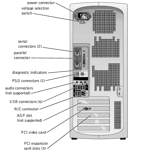
Figure 1-2 shows the back-panel features of the system. Figure 1-3 and Table 1-2 provide information about NIC indicators. For information about diagnostic indicators, see your Installation and Troubleshooting Guide.
Figure 1-2. Back-Panel Features
 |
NOTICE: To help avoid damaging your system, ensure that the voltage selection switch on the
power supply (see Figure 1-2) is set for the voltage that most closely matches the AC power
available in your location before turning on the power. Also, ensure that your monitor and
attached devices are electrically rated to operate with the power available in your location.
|
Figure 1-3. NIC Indicators

Table 1-2. NIC Indicators
|
Indicator
|
Normal Operation
|
Error Condition
|
|---|
Activity | Flashing amber indicates that network data is being sent or received. | When off at the same time that the link indicator is off, the NIC is not connected to the network. |
Link | Steady green indicates that the NIC is connected to a valid link partner on the network. | When off at the same time that the activity indicator is off, the NIC is not connected to the network. |
System Features
Your system offers the following features:
- One of the following processors:
- Intel® Celeron® with a minimum clock speed of at least 2.0 GHz, front-side bus speed of at least 400 MHz, and a minimum of 128 KB of level 2 (L2) cache
- Intel Pentium® 4 with a minimum clock speed of at least 2.2 GHz, front-side bus speed of at least 533 MHz, and a minimum of 512 KB of level 2 cache
- A minimum of 128 MB of DDR 333 and DDR 400 SDRAM ECC memory, upgradable to a maximum of 4 GB by installing 128-, 256-, 512-, or 1-GB unbuffered memory modules in the four memory module sockets on the system board
- Two 1-inch IDE, SATA (when available), or SCSI internal hard drives
 |
NOTE: Hard-drive bus types cannot be mixed. Both drives must use the same bus type.
|
- Integrated IDE controllers for internal IDE hard drives, optical drives (CD, DVD, CD-RW/DVD combination), and optional tape backup drives; integrated SATA controllers (when available) for internal hard drives; optional SCSI controller card for optional SCSI drives
- One 3.5-inch peripheral drive bay for the diskette drive, and two 5.25-inch bays for the following supported drives: CD, DVD, combination CD-RW/DVD, or tape backup unit (IDE)
The system board includes the following built-in features:
- Four 32-bit, 33-MHz PCI expansion slots
- A VGA-compatible ATI RAGE XL video card, containing 8 MB of SDRAM video memory (nonupgradable), and a maximum resolution of 1280 x 1024 pixels and 16.7 million colors (noninterlaced)
- An integrated Gigabit Ethernet NIC, capable of supporting 10-Mbps, 100-Mbps, or 1000-Mbps data rates
- Chassis intrusion alert and padlock tabs for internal security
The following software is included with your system:
- The System Setup program for quickly viewing and changing the system configuration information for your system. For more information on this program, see "Using the System Setup Program."
- Enhanced security features, including a system password and a setup password, available through the System Setup program.
- Diagnostics for evaluating your system's components and devices. For information on using the system diagnostics, see "Running the System Diagnostics" in your Installation and Troubleshooting Guide.
For more information about specific features, see "Technical Specifications." For a list of documents that provide more information on your system's features, see "Other Documents You May Need."
Supported Operating Systems
- Microsoft® Windows® 2000 Server and Windows Server 2003
- Red Hat Linux 9
Power Protection Devices
Certain devices protect your system from the effects of problems such as power surges and power failures.
- Surge protector — Prevents voltage spikes, such as those that may occur during an electrical storm, from entering the system through the electrical outlet. They do not protect against brownouts, which occur when the voltage drops more than 20 percent below the normal AC line voltage level.
- Line conditioner — Maintains a system's AC power source voltage at a moderately constant level and provides protection from brownouts, but does not protect against a complete power loss.
- UPS — Uses battery power to keep the system running when AC power is unavailable. The battery is charged by AC power while it is available so that after AC power is lost, the battery can provide power to the system for a limited amount of time—from 5 minutes to approximately an hour. A UPS that provides only 5 minutes of battery power allows you to save your open files and gracefully shutdown the system. Use surge protectors with all universal power supplies, and ensure that the UPS is UL-safety approved.
Other Documents You May Need

|
The System Information Guide provides important safety and regulatory information. Warranty information may be included within this document or as a separate document. |
- The User's Guide provides information about system features and technical specifications.
- The Installation and Troubleshooting Guide describes how to troubleshoot the system and install or replace system components.
- Operating system documentation describes how to install (if necessary), configure, and use the operating system software.
- Documentation for any components you purchased separately provides information to configure and install these options.
- Updates are sometimes included with the system to describe changes to the system, software, and/or documentation.
|
NOTE: Always read the updates first because they often supersede information in other
documents.
|
- Release notes or readme files may be included to provide last-minute updates to the system or documentation or advanced technical reference material intended for experienced users or technicians.
Obtaining Technical Assistance
If you do not understand a procedure in this guide or if the system does not perform as expected, see your Installation and Troubleshooting Guide.
Dell Enterprise Training and Certification is available; see www.dell.com/training for more information. This service may not be offered in all locations.
Back to Contents Page