Back to Contents Page
Dell™ PowerEdge™ 500SC Systems
Installation and
Troubleshooting Guide
 Configuring the EIDE Subsystem
Configuring the Boot Device
Connecting Drives
Removing and Reinstalling the Drive Cage
Adding or Replacing Hard Drives
Adding or Replacing Other Drives
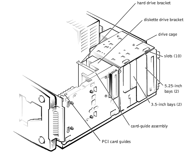
Your system has six drive bays for installing the following types of drives (see Figure 7-1):
- The externally accessible drive bays at the front of the system consist of a 3.5-inch
drive bay that accommodates one 3.5-inch diskette drive (standard) and two
5.25-inch, half height drive bays that can accommodate two 5.25-inch devices—
typically a CD drive and one other device, such as a tape drive.
- There are three internally accessible 3.5-inch bays that can hold up to three 1-inch
EIDE hard drives.
Figure 7-1. Drive Bays
The following sections contain general information and information that you will need in
several of the installation procedures. The remaining sections address each type of drive
removal and installation.
The enhanced integrated drive electronics (EIDE) subsystem includes two IDE interfaces
(primary and secondary), each of which can support up to two IDE devices such as
high-capacity hard drives, CD drives, DVD drives, and tape drives.
All IDE devices should be configured for the Cable Select jumper position, which assigns
master and slave status to devices by their position on the interface cable. In this
configuration, the drive attached to the last connector on the interface cable is the master
or boot drive (drive 0) and the drive attached to the middle connector on the interface
cable is the slave drive (drive 1). The drive jumpers are located on the back of each IDE
drive. See the drive's documentation for instructions on setting the Cable Select jumper
position.
If you plan to boot the system from a hard drive, the hard drive must be attached to the
primary IDE controller. The device that the system boots from is determined by the boot
order specified in the System Setup program.
The System Setup program provides options that the system uses to scan for installed boot
devices. Refer to the User's Guide for information about the System Setup program.
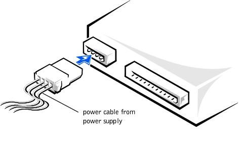
When installing a drive, you connect two cables—a DC power cable and an interface
cable—to the back of the drive. Your drive's power input connector (to which you connect
the DC power cable) resembles the connector shown in Figure 7-2.
Figure 7-2. Connecting the Power Cable
 |
NOTICE: When you attach the interface cable to the drive, match the colored strip on the cable
with pin 1 on the drive.
|
Your drive's interface connector resembles the connector shown in Figure 7-3.
Figure 7-3. Connecting the Interface Cable

The drive cage has two 5.25-inch bays and two 3.5-inch bays.
- Turn off the system, including any external devices, and disconnect the system from
its electrical outlet.
- Remove the system cover (see "Removing the System Cover and Support Beam" in
"Troubleshooting Your System").
- Remove the bezel (see "Removing the Bezel" in "Troubleshooting Your System").
- Disconnect the interface cable and the power cable from all drives installed in the
drive cage. Note the location and orientation of all cables attached to the drives.
- Remove the screw from the side of the drive cage (see Figure 7-4). Pull the drive cage
toward you to unlock it from the system. Lift out the drive cage.
Figure 7-4. Removing and Reinstalling the Drive Cage
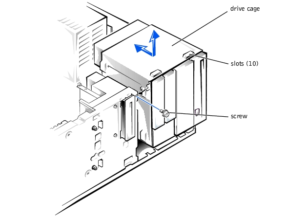
- With the slots on the drive cage extending slightly beyond the front of the system,
lower the drive cage and slide it toward the back of the system until the cage locks into
place (see Figure 7-4).
- Secure the drive cage to the system with the screw you removed in step 5 of
"Removing the Drive Cage" (see Figure 7-4).
- Connect the interface cable and the power cable to all drives installed in the drive
cage.
- Replace the bezel (see "Replacing the Bezel" in "Troubleshooting Your System").
- Replace the system cover (see "Replacing the System Cover and Support Beam" in
"Troubleshooting Your System").
Your system includes bays or brackets for up to three 1-inch IDE hard drives.
|
NOTICE: When replacing a hard drive, set the jumpers on the replacement hard drive to match
the jumpers on the hard drive you removed. For additional information about jumper settings on
IDE drives, see "Configuring the EIDE Subsystem."
|
Each of the two 3.5-inch bays in the drive cage can accommodate a 1-inch IDE hard drive.
- Turn off the system, including any external devices, and disconnect the system from
its electrical outlet.
- Remove the system cover (see "Removing the System Cover and Support Beam" in
"Troubleshooting Your System").
- Remove the bezel (see "Removing the Bezel" in "Troubleshooting Your System").
- Remove the drive cage from the system (see "Removing the Drive Cage").
- Remove the three drive-mounting screws, two from the bottom and one from the left
side (see Figure 7-5).
Figure 7-5. Adding or Removing a Hard Drive in the Lower
3.5-inch Bay
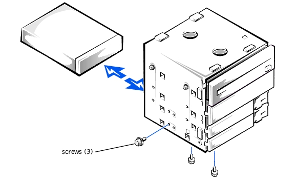
- Slide the hard drive out of the back of the drive cage.
- Reinstall the drive cage into the system (see "Reinstalling the Drive Cage").
- Replace the bezel (see "Replacing the Bezel" in "Troubleshooting Your System").
- Replace the system cover (see "Replacing the System Cover and Support Beam" in
"Troubleshooting Your System").
- Turn off the system, including any external devices, and disconnect the system from
its electrical outlet.
- Remove the system cover (see "Removing the System Cover and Support Beam" in
"Troubleshooting Your System").
- Remove the bezel (see "Removing the Bezel" in "Troubleshooting Your System").
- Remove the drive cage from the system (see "Removing the Drive Cage").
- Slide the drive into the back opening of the bay over the two small grooves on the
bottom of the bay.
- Secure the drive with three drive-mounting screws, two from the bottom and one from
the left side (see Figure 7-5).
- Reinstall the drive cage into the system (see "Reinstalling the Drive Cage").
- Replace the bezel (see "Replacing the Bezel" in "Troubleshooting Your System").
- Replace the system cover (see "Replacing the System Cover and Support Beam" in
"Troubleshooting Your System").
- Plug your system and any external devices into their electrical outlets, and turn them
on.
- See the drive documentation for instructions on installing any software required for
hard drive operation.
- Turn off the system, including any external devices, and disconnect the system from
its electrical outlet.
- Remove the system cover (see "Removing the System Cover and Support Beam" in
"Troubleshooting Your System").
- Remove the bezel (see "Removing the Bezel" in "Troubleshooting Your System").
- Remove the drive cage from the system (see "Removing the Drive Cage").
- Remove the two screws securing the drive to the drive cage (see Figure 7-6). Insert
your screwdriver into the reticular slot on the right side of the drive cage to access the
screw securing the right side of the drive.
Figure 7-6. Adding or Replacing a Hard Drive in the Upper
3.5-inch Bay
- Slide the hard drive out the back of the drive cage.
- Reinstall the drive cage in the system (see "Reinstalling the Drive Cage").
- Replace the bezel (see "Replacing the Bezel" in "Troubleshooting Your System").
- Replace the system cover (see "Replacing the System Cover and Support Beam" in
"Troubleshooting Your System").
- Turn off the system, including any external devices, and disconnect the system from
its electrical outlet.
- Remove the system cover (see "Removing the System Cover and Support Beam" in
"Troubleshooting Your System").
- Remove the bezel (see "Removing the Bezel" in "Troubleshooting Your System").
- Remove the drive cage (see "Removing the Drive Cage").
- Slide the hard drive into the bay through the back of the drive cage.
- Secure the hard drive to the drive cage with two screws as shown in Figure 7-6. To
secure the screw on the right side of the drive, you must position the screw over the
screw hole through the back of the drive cage while inserting your screwdriver into the
reticular slot on the right side of the drive cage.
- Reinstall the drive cage in the system (see "Reinstalling the Drive Cage").
- Replace the bezel (see "Replacing the Bezel" in "Troubleshooting Your System").
- Replace the system cover (see "Replacing the System Cover and Support Beam" in
"Troubleshooting Your System").
- Plug your system and any external devices into their electrical outlets, and turn them
on.
- See the drive documentation for instructions on installing any software required for
hard drive operation.
The 3.5-inch bracket next to the floppy drive accommodates a 1-inch IDE hard drive.
|
NOTICE: Do not install a hard drive in the lower card-guide assembly bracket next to the card
guides. Installing a drive in the lower card-guide assembly bracket is not supported in this
system.
|
- Turn off the system, including any external devices, and disconnect the system from
its electrical outlet.
- Remove the system cover (see "Removing the System Cover and Support Beam" in
"Troubleshooting Your System").
- Remove the bezel (see "Removing the Bezel" in "Troubleshooting Your System").
- Disconnect the interface cable and the power cable from the hard drive.
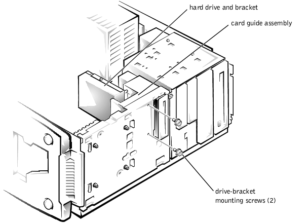
- Remove the screws securing the drive bracket (see Figure 7-7).
- Slide the drive bracket and hard drive toward the back of the system and lift them out
of the system.
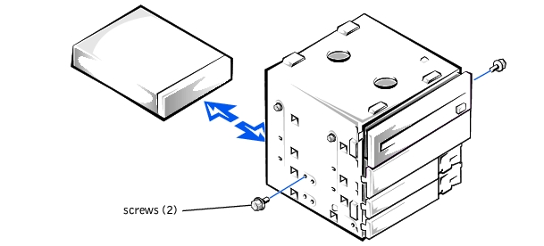
Figure 7-7. Removing the Hard Drive and Drive Bracket
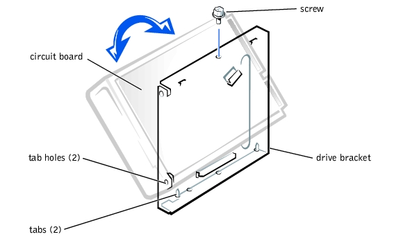
- Remove the screw securing the hard drive to the drive bracket, and rotate the drive out
of the bracket (see Figure 7-8).
Figure 7-8. Detaching or Attaching the Hard Drive
.
- Align the bracket tabs with the slots in the system, and slide the bracket into place.
Secure the bracket with the screws you removed in step 5.
- Replace the bezel (see "Replacing the Bezel" in "Troubleshooting Your System").
- Replace the system cover (see "Replacing the System Cover and Support Beam" in
"Troubleshooting Your System").
- Turn off the system, including any external devices, and disconnect the system from
its electrical outlet.
- Remove the system cover (see "Removing the System Cover and Support Beam" in
"Troubleshooting Your System").
- Remove the bezel (see "Removing the Bezel" in "Troubleshooting Your System").
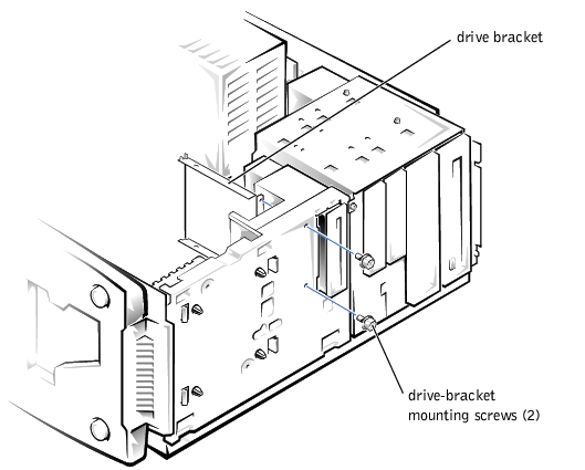
- Remove the screws securing the upper drive bracket, and lift the bracket out of the
system (see Figure 7-9).
Figure 7-9. Removing the Drive Bracket
- Orient the drive with its circuit board facing the inside of the bracket.
- Align the bracket tabs with the two tab holes in the side of the drive, and rotate the
drive into the bracket. Then secure the screw as illustrated in Figure 7-8.
- Align the bracket tabs with the slots in the system, and slide the hard drive and bracket
into place. Secure the bracket with the screws you removed in step 4.
- Connect a power cable to the hard drive.
|
NOTICE: When you attach the interface cable to the hard drive, match the colored strip on the
cable with pin 1 on the drive.
|
- Connect an interface cable to the hard drive.
- Replace the bezel (see "Replacing the Bezel" in "Troubleshooting Your System").
- Replace the system cover (see "Replacing the System Cover and Support Beam" in
"Troubleshooting Your System").
- Plug your system and any external devices into their electrical outlets, and turn them
on.
- See the drive documentation for instructions on installing any software required for
drive operation.
Your system includes a diskette drive and a CD drive. You can add drives, such as DVD
drives and tape drives, using the procedures in the following sections.
- Turn off the system, including any external devices, and disconnect the system from
its electrical outlet.
- Remove the system cover (see "Removing the System Cover and Support Beam" in
"Troubleshooting Your System").
- Remove the bezel (see "Removing the Bezel" in "Troubleshooting Your System").
- Remove the drive cage from the system (see "Removing the Drive Cage").
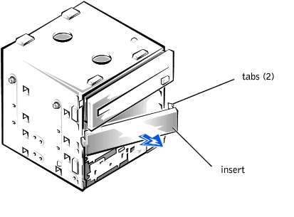
- Press in the two tabs on the insert, and rotate the insert toward you to remove it (see
Figure 7-10).
Figure 7-10. Removing the Insert
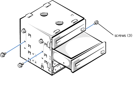
- Slide the new drive into the bay, and secure the drive with the three screws (see
Figure 7-11).
Figure 7-11. Adding or Removing a 5.25-inch Device
- Reinstall the drive cage in the system (see "Reinstalling the Drive Cage").
- Replace the bezel (see "Replacing the Bezel" in "Troubleshooting Your System").
- Replace the system cover (see "Replacing the System Cover and Support Beam" in
"Troubleshooting Your System").
- Plug your system and any external devices into their electrical outlets, and turn them
on.
- See the drive documentation for instructions on installing any software required for
drive operation.
- Turn off the system, including any external devices, and disconnect the system from
its electrical outlet.
- Remove the system cover (see "Removing the System Cover and Support Beam" in
"Troubleshooting Your System").
- Remove the bezel (see "Removing the Bezel" in "Troubleshooting Your System").
- Remove the drive cage (see "Removing the Drive Cage").
- Remove the three drive-mounting screws and slide the drive out of the drive bay (see
Figure 7-11).
- Reinstall the drive cage in the system (see "Reinstalling the Drive Cage").
- Replace the bezel (see "Replacing the Bezel" in "Troubleshooting Your System").
- Replace the system cover (see "Replacing the System Cover and Support Beam" in
"Troubleshooting Your System").
- Turn off the system, including any external devices, and disconnect the system from
its electrical outlet.
- Remove the system cover (see "Removing the System Cover and Support Beam" in
"Troubleshooting Your System").
- Remove the bezel (see "Removing the Bezel" in "Troubleshooting Your System").
- Disconnect the power and interface cables from the back of the diskette drive.
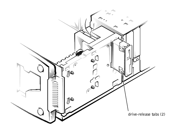
- Press the two drive-release tabs, and slide the drive out of the drive bay (see
Figure 7-12).
Figure 7-12. Removing and Installing a Diskette Drive
- Replace the bezel (see "Replacing the Bezel" in "Troubleshooting Your System").
- Replace the system cover (see "Replacing the System Cover and Support Beam" in
"Troubleshooting Your System").
- Turn off the system, including any external devices, and disconnect the system from
its electrical outlet.
- Remove the system cover (see "Removing the System Cover and Support Beam" in
"Troubleshooting Your System").
- Remove the bezel (see "Removing the Bezel" in "Troubleshooting Your System").
- Before you install the new diskette drive, transfer the drive-release tabs from the drive
you removed to the replacement drive.
- Slide the diskette drive into the drive bay until the two drive-release tabs engage (see
Figure 7-12).
- Connect a power cable and the diskette drive interface cable to the diskette drive.
- Replace the bezel (see "Replacing the Bezel" in "Troubleshooting Your System").
- Replace the system cover (see "Replacing the System Cover and Support Beam" in
"Troubleshooting Your System").
- Plug your system and any external devices into their electrical outlets, and turn them
on.
- See the drive documentation for instructions on installing any software required for
drive operation.
Back to Contents Page