Back to Contents Page
Dell™ PowerEdge™ 500SC Systems
Installation and
Troubleshooting Guide
If your system is not working as expected, begin troubleshooting using the procedures in
this section. This section guides you through some initial checks and procedures that can
solve basic system problems and provides troubleshooting procedures for components
inside the system. Before you start any of the procedures in this section, take the following
steps:
- Lay the system on its side.
- Read the "Safety Instructions" in your System Information document.
- Read "Running the System Diagnostics" for information about running diagnostics.
The procedures in this guide require that you remove the cover and work inside the system.
While working inside the system, do not attempt to service the system except as explained
in this guide and elsewhere in your system documentation. Always follow the instructions
closely. Make sure to review all of the procedures in "Safety Instructions" in your System
Information document.
Working inside the system is safe—if you observe the following precaution.

|
CAUTION: See "Protecting Against Electrostatic Discharge" in the "Safety
Instructions" in your System Information document before performing any
procedure which requires you to open the cover.
|
The system is enclosed by a bezel and a cover. To upgrade or troubleshoot the system,
remove the system cover and support beam to gain access to internal components.
 |
NOTICE: To avoid damaging the system board, disconnect the power cable from the electrical
outlet and from the back of the system, then press the power button before you remove the
system cover. The system board continues to receive a small amount of power when the system is
turned off and attached to an electrical outlet.
|
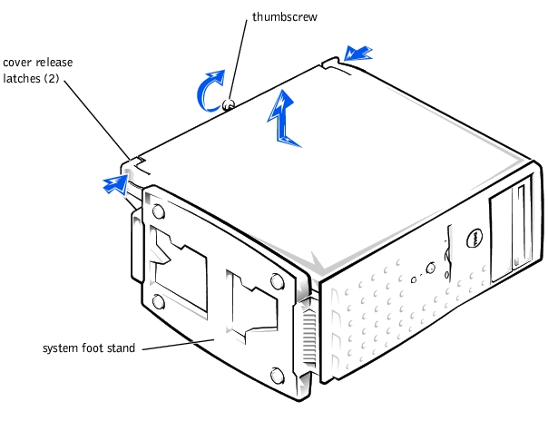
- Lay the system on its right side, with the system foot stand off the edge of the work
surface.
- Loosen the captive thumbscrew that secures the cover to the back of the system.
|
|
CAUTION: To prevent cuts, keep your hands clear of the metal edges on the
system as you slide back the cover.
|
- Face the front of the system. Use your thumbs to press in both latches while pushing
the cover backward. Move the cover back slightly, and then lift it straight up (see
Figure 5-1).
If necessary, use both hands and work one side at a time.
Figure 5-1. Removing the System Cover
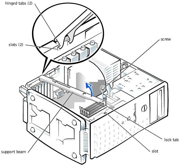
- Remove the screw from the support beam as shown in Figure 5-2.
- Pull the front end of the support beam until it snaps free from its fastener. Rotate the
front of the beam upward until the hinged tabs on the back of the beam clear their
slots (see Figure 5-2).
Figure 5-2. Removing and Replacing the Support Beam
- Check that no tools or parts are left inside the system.
- Slip the support beam's hinged tabs into their slots and lower the beam until the lock
tab snaps into the retaining slot (see Figure 5-2).
- Replace the screw you removed in step 4 of "Removing the System Cover and Support
Beam."
- Fit the cover over the sides of the chassis and slide the cover forward until it locks in
place.
- Secure the cover with the thumbscrew.
The front bezel has status and attention indicators. You must remove the system cover in
order to remove the bezel.
- Remove the system cover (see "Removing the System Cover and Support Beam").
- Press the three tabs along the side of the bezel (see Figure 5-3).
- Swing the bezel away from the system, disengage the hooks, and carefully pull the
bezel away from the system.
Figure 5-3. Removing and Replacing the Bezel
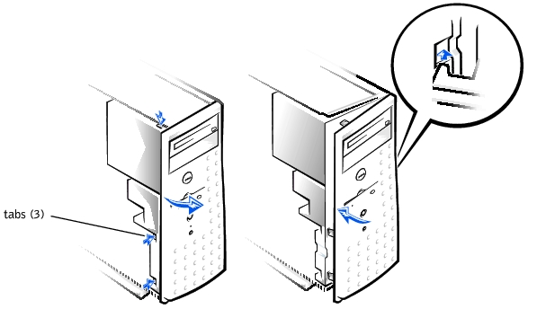
Insert the bezel hooks into the system slots, and snap the bezel back onto the system (see
Figure 5-3).
This section provides troubleshooting procedures for equipment that connects directly to
the I/O panel of the system, such as the monitor, keyboard, or mouse. Before you perform
any of the procedures, see "Checking Connections and Switches" in "Indicators, Messages,
and Codes."
- Monitor
- Monitor interface cable
- Video memory
- Video logic
- Check the system and power connections to the monitor.
- Run the video tests in the system diagnostics.
If the tests run successfully, the problem is not related to video hardware. Go to "Finding Software Solutions."
If the tests did not run successfully see "Getting Help" for instructions on obtaining technical assistance.
- A system error message indicates a keyboard problem
- Look at the keyboard and the keyboard cable for any signs of damage.
- Press and release each key on the keyboard.
If the keyboard and its cable appear to be free of physical damage, and the keys work, go to step 4.
If the keyboard or its cable are damaged, continue to step 3.
- Swap the faulty keyboard with a working keyboard.
If the problem is resolved, the keyboard must be replaced. See "Getting Help," for instructions on obtaining technical assistance.
- Run the keyboard test in the system diagnostics.
If you can use the keyboard to select the keyboard test, go to step 6.
If you cannot use the keyboard to select the keyboard test, continue to step 5.
- Swap the faulty keyboard with a working keyboard.
- Did the keyboard test run successfully?
If the problem is resolved, the keyboard must be replaced. If the problem is not resolved, the keyboard controller on the system board is faulty. See "Getting Help," for instructions on obtaining technical assistance.
- A system error message indicates an I/O port problem
- A device connected to the port does not function properly
- Check the system setup. See "Using the System Setup Program" in the User's Guide
for instructions.
If the system setup is correct, go to step 4.
- Change the necessary statements in the system setup. If the port problem is confined
to a particular application program, see the application program's documentation for
specific port configuration requirements.
- Reboot the system from the diagnostics diskette, and run the serial port test and/or the
parallel port test in the system diagnostics.
If the tests did not run successfully, see "Getting Help," for instructions on obtaining technical assistance.
- If the problem persists, see one of the following procedures, "Troubleshooting a
Parallel Printer" or "Troubleshooting a Serial I/O Device," depending on the
malfunctioning device.
- Device connected to the serial ports is not working
- Turn off the system and any peripheral devices connected to the serial port.
- Swap the interface cable with a known working cable.
If the problem is resolved, the interface cable must be replaced. See "Getting Help," for instructions on obtaining technical assistance.
- Turn off the system and the serial device, and swap the device with a comparable
device.
- Turn on the power to the system and the serial device.
If the problem is resolved, the serial device must be replaced. If the problem is not resolved, see "Getting Help," for instructions on obtaining technical assistance.
- Parallel printer is not working
- Turn off the power from the printer and the system.
- Swap the parallel printer interface cable with a known working cable.
- Turn on the power to the printer and the system.
- Attempt to print with the printer.
If the print operation is successful, the interface cable must be replaced. See "Getting Help," for instructions on obtaining technical assistance.
- Run the printer's self-test.
If the self-test is not successful, the printer is probably defective. If the printer was purchased from Dell, see "Getting Help," for instructions on obtaining technical assistance.
- Attempt to print on the parallel printer.
If the print operation is not successful, the see "Getting Help," for instructions on obtaining technical assistance.
- A system error message indicates a problem
- Device connected to the port is not working
- Enter the System Setup program, and check that the USB ports are enabled. See
"Using the System Setup Program" in the User's Guide for instructions.
- Turn off the system and any USB devices.
If there is only one USB device connected to the system, go to step 5.
- Disconnect the USB devices, and connect the malfunctioning device to the other port.
- Apply power to the system and the reconnected device.
If the problem is resolved, the USB port may be defective. See "Getting Help," for instructions on obtaining technical assistance.
- If possible, swap the interface cable with a known working cable.
If the problem is resolved, the interface cable must be replaced. See "Getting Help," for instructions on obtaining technical assistance.
- Turn off the system and the USB device, and swap the device with a comparable
device.
- Turn on the power to the system and the USB device.
If the problem is resolved, the USB device must be replaced. If the problem is not resolved, see "Getting Help," for instructions on obtaining technical assistance.
- NIC cannot communicate with the network
- Enter the System Setup program and confirm that the NIC is enabled.
See "Using the System Setup Program" in the User's Guide for instructions.
- Check the two indicators on the left and right corners of the NIC connector on the
system's back-panel (see Figure 5-4).
The green link indicator shows that the adapter is connected to a valid link partner. The amber activity indicator lights if network data is being sent or received.
- If the link indicator is not on, check all cable connections.
- Try changing the auto-negotiation setting, if possible.
- Try another port on the switch or hub.
- If the activity indicator does not light, the network driver files might be damaged or
deleted.
- Reinstall the drivers.
- Make sure the appropriate drivers are installed and the protocols are bound.
Figure 5-4. NIC Indicators

In Figure 5-5, the system cover and front bezel are removed to provide an interior view of
the system.
Figure 5-5. Inside the System
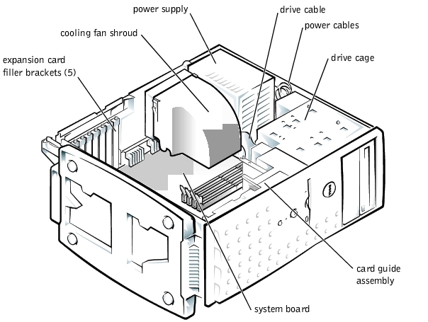
The system board holds the system's control circuitry and other electronic components.
Several hardware options such as the microprocessor and memory are installed directly on
the system board. The system board can accommodate up to five PCI expansion cards (two
cards at 64-bit/66 MHz or 64-bit/33 MHz, and three cards at 32-bit/33 MHz).
The drive cage contains two externally accessible, 5.25-inch drive bays that provide space
for up to two drives, including a CD or DVD drive and one other device, such as a tape
drive. The drive cage also provides space for up to two 1-inch IDE hard drives.
Additionally, the card guide assembly provides two additional brackets for a 3.5-inch
diskette drive and a 1-inch IDE hard drive.
|
NOTICE: Do not install a hard drive in the lower card-guide assembly bracket next to the card
guides. Installing a drive in the lower card-guide assembly bracket is not supported in this
system.
|
When you look inside the system, note the DC power cables leading from the power supply.
The power cables supply power to the system board, drives, and any expansion cards that
connect to external peripheral.
The wide ribbon cables are the interface cables for internal drives. For the diskette drive, an
interface cable connects the drive to an interface connector on the system board or on an
expansion card. For IDE devices, interface cables connect the devices to an IDE connector
on the system board (for more information, see "Installing Drives").
During an installation or troubleshooting procedure, you may be required to change a
jumper. For information on the system board jumpers, see "Jumpers and Connectors."
The optional system management server agent monitors critical system voltages and
temperatures, the system cooling fans, and the status of the hard drives in the system. The
server agent generates alert messages that appear in the alert log window. For information
about the alert log window and options, see the system management server agent
documentation.
- Liquid spills
- Splashes
- Excessive humidity
- Turn off the system, including any attached peripherals, and disconnect the system
from the electrical outlet.
- Remove the system cover.
- Remove all expansion cards installed in the system.
- Let the system dry thoroughly for at least 24 hours.
- Replace the system cover, reconnect the system to the electrical outlet, and turn on
the system.
If the system does not start up properly, see "Getting Help," for instructions on obtaining technical assistance.
- If the system starts up normally, shut down the system and reinstall all expansion cards
you removed in step 3.
- Run the system board tests in the system diagnostics to confirm that the system is
working properly.
If the tests did not complete successfully, see "Getting Help," for instructions on obtaining technical assistance.
- System dropped or damaged
- Check the expansion-card connections to the system board.
- Make sure that all cables are properly connected and that all components are properly
seated in their connectors and sockets.
- Run the system board tests in the system diagnostics.
If the tests did not complete successfully, see "Getting Help," for instructions on obtaining technical assistance.
- Error message shows problem with the battery
- System Setup program loses the system configuration information
- System date and time will not stay current
- Check the connection of the coin cell battery to the system board.
See "Replacing the System Battery" in "Installing System Board Options."
 |
WARNING: There is a danger of a new battery exploding if it is incorrectly
installed. Replace the battery only with the same or equivalent type
recommended by the manufacturer. Discard used batteries according to the
manufacturer's instructions.
|
- If the problem is not resolved by reseating the battery, replace the battery.
If the problem is not resolved by replacing the battery, see "Getting Help," for instructions on obtaining technical assistance.
- Green power indicator on the system bezel is not lit
- Server management application program issues a power supply-related error message
- Check the power outlet and power cable (see "Checking Connections and Switches"
in "Indicators, Messages, and Codes").
- Turn off the system, including any attached peripherals, and disconnect all the power
cables from the electrical outlets.
|
|
CAUTION: See "Protecting Against Electrostatic Discharge" in your System
Information document.
|
- Remove the system cover. See "Replacing the System Cover and Support Beam."
- Check the power cable connection to the POWER connector on the system board.
If the problem is not resolved, see "Getting Help," for instructions on obtaining technical assistance.
- Fan not operating
- Server management application program issues a fan-related error message
- Turn off the system, including any attached peripherals, and disconnect all the power
cables from the electrical outlets.
- Remove the system cover (see "Removing the System Cover and Support Beam").
- Check the fan cable connection to the SYS_FAN2 connector on the system board.
If the problem is not resolved, see "Getting Help," for instructions on obtaining technical assistance.
- Error message indicates an expansion-card problem
- Expansion card seems to perform incorrectly or not at all
- Turn off the system, including any attached peripherals, and disconnect all the power
cables from the electrical outlets.
- Remove the system cover (see "Removing the System Cover and Support Beam").
- Verify that each expansion card is firmly seated in its connector.
- Verify that any appropriate cables are firmly connected to their corresponding
connectors on the expansion cards.
- Install the system cover.
- Connect the system to an electrical outlet and turn on the system. If the problem still
exists, go to step 7.
- Turn off the system and disconnect the system from its electrical outlet.
- Remove the system cover.
- Remove all expansion cards installed in the system.
- Install the system cover.
- Connect the system to an electrical outlet and turn on the system.
- Run the system memory tests in the system diagnostics.
If the tests do not complete successfully, see "Getting Help," for information on obtaining technical assistance.
- Reinstall one of the expansion cards you removed in step 9 (see "Installing Expansion
Cards" in Installing System Board Options").
- Replace the system cover, reconnect the system to the electrical outlet, and turn on
the system.
If the problem still exists, repeat steps 13 and 14 for each of the remaining expansion cards.
If you have reinstalled all of the expansion cards and the system memory tests are still failing, see "Getting Help," for information on obtaining technical assistance.
- Faulty memory module
- Faulty system board
- Turn on the power to the system, including any attached peripherals.
If there is not an error message, go to step 4.
- Enter the System Setup program to check the system memory setting.
See "Using the System Setup Program," in the User's Guide for instructions.
- If the amount of memory installed does match the system memory setting, go to
step 8.
- Turn off the system, including any attached peripherals, and disconnect the system
from its electrical outlet.
|
|
CAUTION: See "Protecting Against Electrostatic Discharge" in the safety
instructions in your System Information document.
|
- Remove the system cover (see "Removing the System Cover and Support Beam").
- Reseat the memory modules in their sockets.
- Replace the system cover, reconnect the system to the electrical outlet, and turn on
the system.
- Enter the System Setup program and check the system memory again.
- Does the amount of memory installed match the system memory?
If the amount of memory installed does not match the system memory setting, continue to step 10.
- Reboot the system, and observe the monitor screen and the Num Lock, Caps Lock,
and Scroll Lock indicators on the keyboard.
If the monitor screen remains blank, and the Num Lock, Caps Lock, and Scroll Lock indicators on the keyboard remain on, continue to step 11.
If the monitor screen does not remain blank, and the Num Lock, Caps Lock, and Scroll Lock indicators on the keyboard remain on, continue to step 16.
- Repeat steps 4 and 5.
 |
NOTE: There are multiple configurations for the memory modules; see "Memory Module
Installation Guidelines" in "Installing System Board Options." The following steps are an
example of one configuration.
|
- Swap the memory module in socket DIMM_A with one of the same capacity.
- Replace the system cover, reconnect the system to the electrical outlet, and turn on
the system.
- Reboot the system, and observe the monitor screen and the indicators on the
keyboard.
- If the problem still exists, repeat steps 12 through 14 for each memory module
installed.
If the problem is not resolved, see "Getting Help," for instructions on obtaining technical assistance.
- Run the system memory test in the system diagnostics.
If the test does not complete successfully, see "Getting Help," for instructions on obtaining technical assistance.
- Monitor not operating
- Monitor interface cable not connected correctly or is faulty
- Video logic problems
- Check the system and power connections to the monitor.
- Run the video tests in the system diagnostics.
If the tests run successfully, the problem is not related to video hardware. See "Finding Software Solutions."
If the tests did not run successfully see "Getting Help," for instructions on obtaining technical assistance.
- Error message indicating a system board problem
- Turn off the system, including any attached peripherals, and disconnect the system
from its electrical outlet.
- Remove the system cover (see "Removing the System Cover and Support Beam").
- Remove all expansion cards.
- Replace the system cover, reconnect the system to power, and turn on the system.
- Run the system board tests in the system diagnostics.
If the tests does not run successfully, see "Getting Help," for instructions on obtaining technical assistance.
- Turn off the system, disconnect it from power, and remove the system cover.
- Reinstall one of the expansion cards that you removed in step 3 (see "Installing
Expansion Cards" in Installing System Board Options").
- Replace the system cover, reconnect the system to the electrical outlet, and turn on
the system.
- Run the system board tests again.
Did the tests run successfully?
If the tests does not complete successfully, see "Getting Help," for instructions on obtaining technical assistance.
- Repeat steps 7 through 9 for the remaining expansion cards that you removed in
step 3.
If you have reinstalled all of the expansion cards and the problem still persists, see "Getting Help," for instructions on obtaining technical assistance.
- Error message indicating a diskette drive problem during execution of either the boot
routine or the system diagnostics
- Enter the System Setup program, and verify that the system is configured correctly.
See "Using the System Setup Program" in the User's Guide for instructions.
- Run the diskette drive tests in the system diagnostics to see whether the diskette drive
now works correctly.
- Turn off the system, including any attached peripherals, and disconnect the system
from its electrical outlet.
- Remove the system cover.
- Verify that the diskette drive interface cable is securely connected between the diskette
drive assembly and the system board.
- Replace the system cover, reconnect the system to the electrical outlet, and turn on
the system, including any attached peripherals.
- Run the diskette drive tests in the system diagnostics to determine whether the
diskette drive works correctly.
- If the drive still does not work, remove all expansion cards.
- Run the diskette drive tests in the system diagnostics to determine whether the
diskette drive now works correctly.
If the test ran successfully, an expansion card may be conflicting with the diskette drive logic, or you may have a faulty expansion card. Continue to step 11.
If the test failed, see "Getting Help," for instructions on obtaining technical assistance.
- Reinstall one of the expansion cards you removed in step 9.
- Retest and run the diskette drives test in the system diagnostics to determine whether
the diskette drive subsystem now works correctly.
- Repeat steps 11 and 12 until all expansion cards have been reinstalled or until one of
the expansion cards prevents the system from booting from the diagnostics diskette.
If the problem is not resolved, see "Getting Help," for instructions on obtaining technical assistance.
- System cannot read data from CD
- CD drive indicator fails to flash during boot
- Turn off the system, including any attached peripherals, and disconnect the system
from its electrical outlet.
- Remove the system cover.
- Verify that the CD drive interface cable is securely connected between the CD drive
assembly and the system board.
- Replace the system cover, reconnect the system to the electrical outlet, and turn on
the system, including any attached peripherals.
- Run the IDE devices tests in the system diagnostics to determine whether the CD
drive now works correctly.
If the problem is not resolved, see "Getting Help," for instructions on obtaining technical assistance.
|
|
CAUTION: This troubleshooting procedure can destroy data stored on the hard
drive. Before you proceed, back up all the files on the hard drive.
|
- Turn off the system, including any attached peripherals, and disconnect the system
from its electrical outlet.
- Remove the system cover.
- Verify that the hard drive interface cable is securely connected between the hard drive
assembly and the system board.
- Replace the system cover, reconnect the system to the electrical outlet, and turn on
the system, including any attached peripherals.
- Run the IDE devices tests in the system diagnostics to determine whether the hard
drive now works correctly.
If the problem is not resolved, see "Getting Help," for instructions on obtaining technical assistance.
Back to Contents Page
 Safety First—For You and Your System