Back to Contents Page
Installing Drives
Dell™ PowerEdge™ 800 Systems Installation and Troubleshooting Guide
 Connecting Drives
Front-Panel Drive Inserts
Diskette Drive
5.25-Inch Drives
Hard Drives
Cabled SATA and SCSI Hard Drives
Front-Access SCSI Hard Drives (Non-Hot-Plug)
Hot-Plug SCSI Hard Drives
Installing the Optional SCSI Backplane Board
Installing a RAID Controller Card
Your system supports the following drives:
- Up to two externally accessible 5.25-inch drives (typically optical and tape backup drives). An optical drive is standard in the first external drive bay, and a tape backup device can be installed in the second external drive bay.
- An externally accessible 3.5-inch diskette drive.
- Up to four 1-inch SATA or SCSI hard drives. Four hard drive configurations are available:
Connecting Drives
Interface Cables
Most interface connectors are keyed for correct insertion. Keying ensures that the pin-1 wire in the cable connects to pin 1 in the connectors on both ends. When you disconnect an interface cable, take care to grasp the cable connector, rather than the cable itself, to avoid stress on the cable.
Drive Cable Configurations
Your system can accommodate many different drive configurations, each with specific cable requirements. Table 7-1 shows the cable requirements for common drive configurations.

|
NOTE: Installing SATA and SCSI hard drives in the same system is not supported. |
Table 7-1. Drive Cable Configuration
|
Drives
|
Required Cable
|
Cable Connections
|
|---|
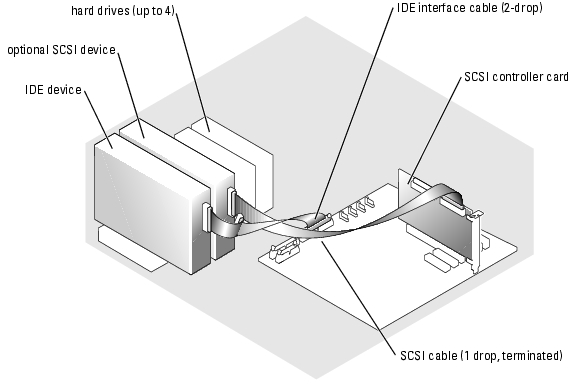
IDE optical drives, and IDE and SCSI tape drives (See Figure 7-4.)
| 40-pin IDE 2-drop cable or SCSI 1-drop cable (terminated)
| IDE drive and primary IDE connector on system board or the SCSI tape device and the SCSI controller card
|
Up to four cabled SATA hard drives (See Figure 7-7.)
| 7-pin SATA hard-drive cable (one cable per drive)
| SATA hard drives and SATA port connectors on the system board, or on a RAID controller card.
|
Up to four cabled (non-hot-plug) SCSI hard-drives (See Figure 7-9.)
| 94-cm (37-inch) SCSI 4-drop cable (terminated)
| SCSI hard drives and SCSI RAID controller or SCSI controller card
|
Up to four front-access or hot-plug SCSI hard drives connected to the SCSI backplane (See Figure 7-12.)
| 38-cm (15-inch) 68-pin SCSI 1-drop cable (unterminated)
| SCSI backplane and the SCSI controller card
|
DC Power Cables
Each drive must connect to a DC power cable from the system power supply. These power cables are used for the 3.5-inch diskette drive, 5.25-inch devices, and hard drives.

|
NOTICE: To avoid electrical damage to internal system components, install a cover connector on any unused connectors on hard-drive power cables. |
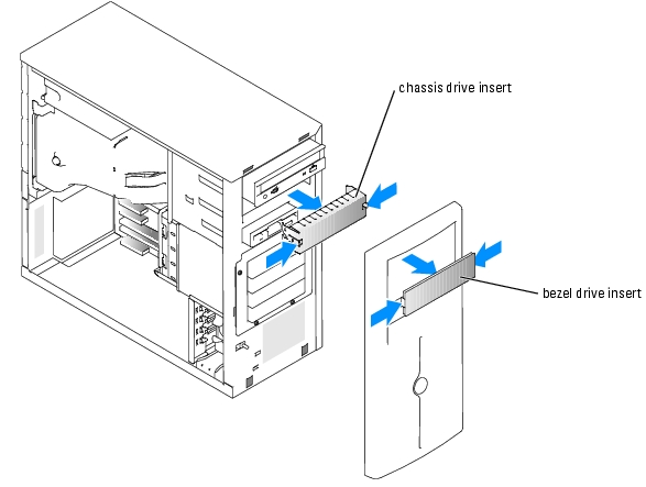
Front-Panel Drive Inserts
To help keep dust and dirt out of the system, a plastic insert in the bezel covers each empty external drive bay. Additionally, each empty external drive bay is covered by a metal insert in the chassis to maintain Federal Communications Commission (FCC) certification of the system.
Before you install a 5.25-inch drive in an empty external drive bay, you must first remove both front-panel drive inserts. If you remove a 5.25-inch drive permanently, you must install both inserts.
Removing the Front-Panel Drive Inserts

|
CAUTION: See your Product Information Guide for complete information about safety precautions, working inside the computer, and protecting against electrostatic discharge. |
- Turn off the system, including any attached peripherals, and disconnect the system from the
electrical outlet.
- Remove the bezel. See "Removing the Bezel" in "Troubleshooting Your System."
- Remove the bezel drive insert (see Figure 7-1):
- From inside the bezel, press the center of the insert outward with your thumbs to loosen
the tabs on the sides of the insert.
- Pull the insert out of the bezel.
- Remove the chassis drive insert (see Figure 7-1):
- Press both sides of the insert to loosen the tabs on the insert.
- Pull the insert out of the chassis.
Figure 7-1. Removing the Front-Panel Drive Inserts
Installing the Front-Panel Drive Inserts
|
|
CAUTION: See your Product Information Guide for complete information about safety precautions, working inside the computer, and protecting against electrostatic discharge. |
|
|
NOTICE: You must install both inserts in an empty 5.25-inch drive bay to maintain Federal Communications Commission (FCC) certification of the system. The inserts also help keep dust and dirt out of the system. |
- Install the chassis drive insert by sliding the insert into the chassis until tabs on the side of the
insert snap into place. See Figure 7-1.
- Install the bezel drive insert by sliding the insert into the bezel until the tabs on the side of
the insert snap into place. See Figure 7-1.
- Install the bezel. See "Installing the Bezel" in "Troubleshooting Your System."
- Reconnect the system to its electrical outlet and turn the system on, including any attached
peripherals.
Diskette Drive
Removing a Diskette Drive
|
|
CAUTION: See your Product Information Guide for complete information about safety precautions, working inside the computer, and protecting against electrostatic discharge. |
- Turn off the system, including any attached peripherals, and disconnect the system from the
electrical outlet.
- Remove the bezel. See "Removing the Bezel" in "Troubleshooting Your System."
- Lay the system on its right side.
- Remove the cover. See "Removing the Cover" in "Troubleshooting Your System."
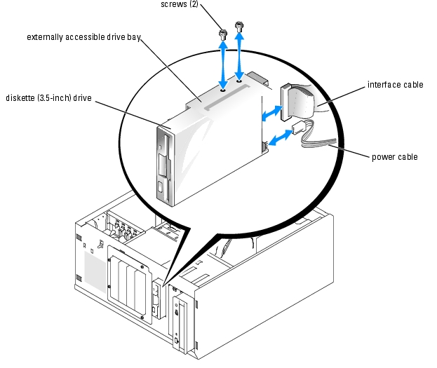
- Disconnect the power cable and the interface cable from the diskette drive. See Figure 7-2.
- Remove the two screws that secure the diskette drive in the externally accessible drive bay. See
Figure 7-2.
- Slide the diskette drive forward out of the drive bay.
Installing a Diskette Drive
|
|
CAUTION: See your Product Information Guide for complete information about safety precautions, working inside the computer, and protecting against electrostatic discharge. |
- Unpack the drive and prepare the drive for installation.
For instructions, see the documentation that accompanied the drive.
- Slide the diskette drive into the externally accessible drive bay.
- Install the two screws that secure the diskette drive in the drive bay. See Figure 7-2.
- Connect the power cable and the interface cable to the diskette drive. See Figure 7-2.
- Install the cover. See "Replacing the Cover" in "Troubleshooting Your System."
- Stand the system upright.
- Install the bezel. See "Installing the Bezel" in "Troubleshooting Your System."
- Reconnect the system to its electrical outlet and turn the system on, including any attached
peripherals.
Figure 7-2. Removing or Installing a Diskette Drive
5.25-Inch Drives
An optical drive is standard in the first external drive bay. An additional IDE or SCSI tape backup device can be installed in the second external drive bay. These drives connect either to the system board or to an optional controller card.
|
|
NOTE: Installing an additional optical drive in the second external drive bay is not supported. |
Installing a 5.25-Inch Drive
|
|
CAUTION: See your Product Information Guide for complete information about safety precautions, working inside the computer, and protecting against electrostatic discharge. |
- Unpack the drive (and controller card, if applicable), and prepare the drive for installation.
For instructions, see the documentation that accompanied the drive.
|
|
NOTE: If you are installing a SCSI tape drive, you must install an Ultra 3 SCSI controller card. The optional SCSI RAID controller card does not support a SCSI tape drive. |
- Turn off the system, including any attached peripherals, and disconnect the system from the
electrical outlet.
- Remove the bezel. See "Removing the Bezel" in "Troubleshooting Your System."
- Lay the system on its right side.
- Remove the cover. See "Removing the Cover" in "Troubleshooting Your System."
- Remove the cooling shroud. See "Removing the Cooling Shroud" in "Installing System
Components."
- Remove the front-panel inserts for the empty external drive bay. See "Removing the Front-
Panel Drive Inserts."
- Slide the drive into the external drive bay.
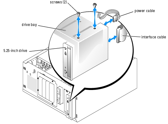
- Install the screws that secure the drive in the drive bay. See Figure 7-3.
Figure 7-3. Installing or Removing a 5.25-Inch Drive
- If a controller card was supplied with the drive, install the controller card in expansion slot 3,
4, or 5. See "Installing an Expansion Card" in "Installing System Components."
- Connect a power cable to the drive. See Figure 7-3.
- Connect the interface cable to the drive and to the appropriate connector on the system
board or controller card (if applicable).
|
|
NOTE: See the documentation that is included with the controller card for more information. |
If you are installing an IDE device (such as an optical drive), connect the interface cable to the IDE device and the IDE connector on the system board. See Figure 7-4.
If you are installing a SCSI device in the second drive bay (such as a tape backup device), connect the interface cable to the device and to channel A on the SCSI controller card. See Figure 7-4.
See Figure A-3 to locate the system board connectors.
|
|
NOTE: A SCSI device attached to a SCSI controller card and an IDE device attached to the system board can be installed together as shown in Figure 7-4. |
Figure 7-4. Connecting a Tape Drive to a SCSI Controller Card
- Ensure that all cables are firmly connected and arranged so that they will not catch on the
computer cover or block airflow inside the system.
- Install the cooling shroud. See "Installing the Cooling Shroud" in "Installing System
Components."
- Install the cover. See "Replacing the Cover" in "Troubleshooting Your System."
- Stand the system upright.
- Install the bezel. See "Installing the Bezel" in "Troubleshooting Your System."
- Reconnect the system to its electrical outlet and turn the system on, including any attached
peripherals.
- Test the drive.
If you installed an IDE device, run the IDE devices tests in the system diagnostics to determine whether the device operates properly. See "Running the System Diagnostics."
If you installed a SCSI device, run the SCSI controllers test in the system diagnostics. See "Running the System Diagnostics."
If you installed a tape drive, see the tape drive software documentation to perform a backup and verification test.
Hard Drives
Your system can contain up to four 1-inch SATA or SCSI hard drives in a optional removable hard-drive bay (see Figure 7-5). These drives connect either to the system board or to an optional controller card.
General Installation Guidelines
Use the following guidelines when installing hard drives:
- You should only use drives that have been tested and approved by the system manufacturer.
- Do not install a mixture of SATA and SCSI hard drives. All hard drives must either be SCSI drives or SATA drives.
- You may need to use different programs than those provided with the operating system to partition and format a hard drive. See the hard drive's documentation for information on setting up the drive.
- When you format a high-capacity hard drive, allow enough time for the formatting to be completed. Long format times for these drives are normal. For example, a large drive can take over an hour to format.
- Do not turn off or reboot your system while the drive is being formatted. Doing so can cause a drive failure.
|
|
NOTE: The hard-drive activity indicator operates only when SATA hard drives are connected directly to the SATA port connectors on the system board. The indicator does not operate with SCSI drives or SATA drives that are attached to a RAID controller card. To identify the indicator, see Figure 2-1. |
Configuring the Boot Drive
The drive or device from which the system boots is determined by the boot order specified in the System Setup program (see "Using the System Setup Program" in your User's Guide). To boot the system from a hard drive or drive array, the drive(s) must be connected to the appropriate controller:
- To boot from a single SATA hard drive, the master drive (drive 0) must be connected to the SATA_0 connector on the system board. To identify system board connectors, see Figure A-3.
- To boot from a single SCSI hard drive, the drive must be connected to a SCSI controller card. See the documentation that accompanied the controller card.
Cabled SATA and SCSI Hard Drives
Removing a Cabled Hard Drive
|
|
CAUTION: See your Product Information Guide for complete information about safety precautions, working inside the computer, and protecting against electrostatic discharge. |
- Turn off the system, including any attached peripherals, and disconnect the system from the
electrical outlet.
- Remove the bezel. See "Removing the Bezel" in "Troubleshooting Your System."
- Lay the system on its right side.
- Remove the cover. See "Removing the Cover" in "Troubleshooting Your System."
- Remove the cooling shroud. See "Removing the Cooling Shroud" in "Installing System
Components."
- Disconnect the interface and power cables to the hard drives in the drive bay.
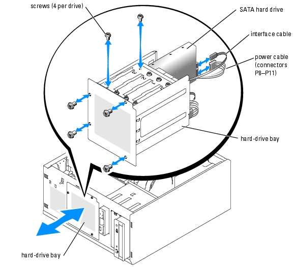
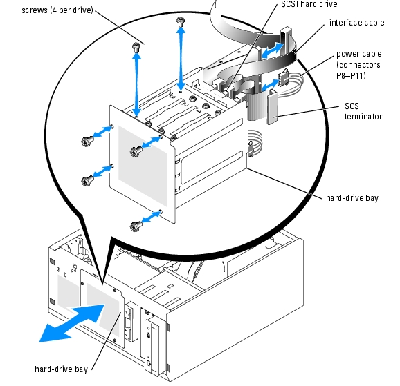
- Remove the hard-drive bay. See Figure 7-5 and Figure 7-6.
- Loosen the four screws that secure the drive bay to the system.
- Slide the hard-drive bay out of the system.
- Remove the drive from the drive bay. See Figure 7-5 and Figure 7-6.
- Remove the screws that secure the drive in the hard-drive bay.
- Slide the drive out of the drive bay.
Figure 7-5. Installing or Removing a SATA Hard Drive
Figure 7-6. Installing or Removing a Cabled SCSI Hard Drive
Installing a Cabled Hard Drive
- Unpack the drive (and controller card, if applicable), and prepare the drive for installation.
For instructions, see the documentation that accompanied the drive.
- Install the hard drive in the hard-drive bay:
- Slide the drive into the drive bay with the back of the drive toward the back of the drive
bay.
- Install the screws that secure the drive in the drive bay.
- Install the hard-drive bay (see Figure 7-5 and Figure 7-6):
- Slide the drive bay into the system until the drive bay contacts the system.
- Install the four screws that secure the drive bay in the system.
|
|
NOTICE: To prevent damage to internal system components, ensure that a connector cap is installed on each available power connector that is not connected to a hard drive. |
- Connect a power cable to each hard drive. See Figure 7-5 and Figure 7-6.
- Connect the hard-drive interface cables to each hard drive.
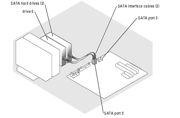
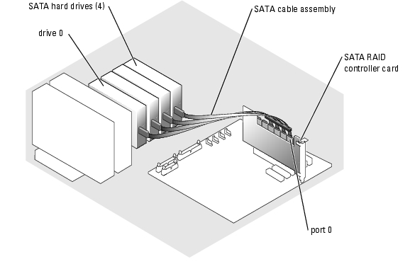
- If you are installing a SATA hard drive, connect the SATA interface cable to the hard drives and to the SATA ports on the system board (see Figure 7-7) or SATA RAID controller board (when available) (see Figure 7-8).
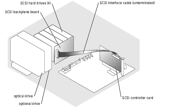
- If you are installing a cabled SCSI drive, connect the SCSI interface cable to the hard drives and to the SCSI controller card. See Figure 7-9.
Figure 7-7. Connecting SATA Hard Drives to the Integrated Drive Controller
Figure 7-8. Connecting SATA Drives to a SATA RAID Controller Card
Figure 7-9. Cabling Four SCSI Hard Drives to the SCSI Controller Card
- Ensure that all cables are firmly connected and arranged so that they will not catch on the
computer cover or block airflow inside the system.
- Install the cooling shroud. See "Installing the Cooling Shroud" in "Installing System
Components."
- Install the cover. See "Replacing the Cover" in "Troubleshooting Your System."
- Stand the system upright.
- Install the bezel. See "Installing the Bezel" in "Troubleshooting Your System."
- Reconnect the system to its electrical outlet and turn the system on, including any attached
peripherals.
- Partition and logically format the hard drive. See the operating system documentation for
more information.
- Install any required device drivers.
- Run the hard drive tests in the system diagnostics to determine whether the drive operates
properly. See "Running the System Diagnostics."
If the drive is connected to a SATA RAID controller card, see the RAID controller card documentation for information on testing the controller.
If the drive is connected to a SCSI controller card, run the SCSI controller tests and the hard-drive tests in the system diagnostics. See "Running the System Diagnostics."
If the hard drive fails the hard-drive tests or does not operate properly, see "Getting Help."
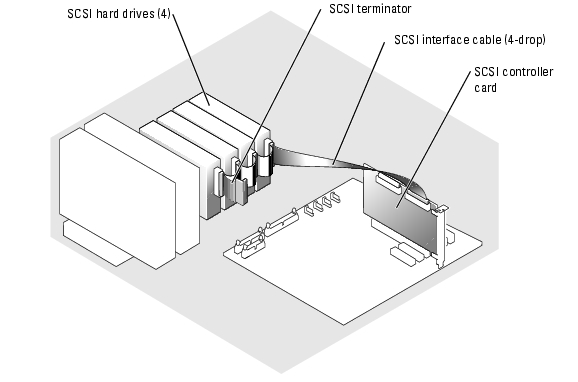
Front-Access SCSI Hard Drives (Non-Hot-Plug)
The drive bays in a system with an optional SCSI backplane board and optional non-RAID SCSI controller card provide space for up to four front-access SCSI hard drives. The hard drives plug into the SCSI backplane board, which is connected to the controller card (see Figure 7-10.) For instructions on installing the optional SCSI backplane board, see "Installing the Optional SCSI Backplane Board."
Figure 7-10. SCSI Hard Drives Connected to a SCSI Controller Card
Removing a Front-Access SCSI Hard Drive (Non-Hot-Plug)
|
|
NOTICE: To prevent data loss, you must shut down the system before removing a SCSI drive carrier, unless a SCSI RAID controller is connected to the SCSI backplane. See "Hot-Plug SCSI Hard Drives" for information on hot-plug drive requirements and operation. |
- Turn off the system, including any attached peripherals, and disconnect the system from the
electrical outlet.
- Remove the bezel. See "Removing the Bezel" in "Troubleshooting Your System."
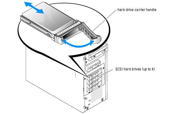
- Open the hard-drive carrier handle to release the drive. See Figure 7-11.
- Slide the hard drive out until it is free of the drive bay.
Figure 7-11. Removing or Installing a SCSI Hard-Drive Carrier
Installing a Front-Access SCSI Hard Drive (Non-Hot-Plug)
- Turn off the system, including any attached peripherals, and disconnect the system from the
electrical outlet.
- Remove the bezel. See "Removing the Bezel" in "Troubleshooting Your System."
- Open the hard-drive carrier handle. See Figure 7-11.
|
|
NOTICE: Do not insert a hard-drive carrier and attempt to lock its handle next to a partially installed carrier. Doing so can damage the partially installed carrier's shield spring and make it unusable. Ensure that the adjacent drive carrier is fully installed. |
- Insert the hard-drive carrier into the drive bay. See Figure 7-11.
- Close the hard-drive carrier handle to lock it in place.
- Install the bezel. See "Installing the Bezel" in "Troubleshooting Your System."
- Reconnect the system to its electrical outlet and turn the system on, including any attached
peripherals.
- Install any required SCSI device drivers.
- Run the SCSI controllers tests and the hard-drive tests in the system diagnostics. See
"Running the System Diagnostics."
If the hard drive fails the hard-drive tests or does not operate properly, see "Getting Help."
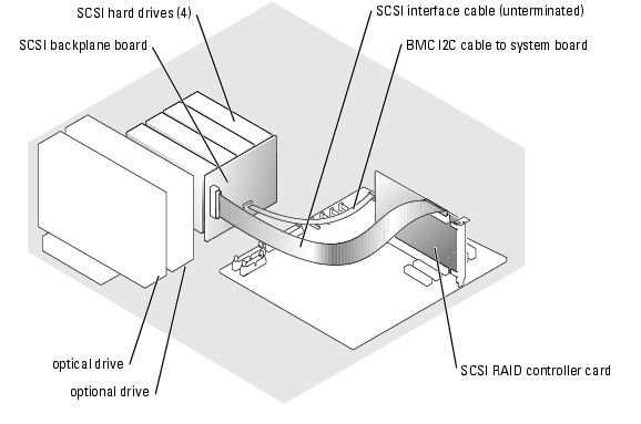
Hot-Plug SCSI Hard Drives
Systems with an optional SCSI backplane board and an optional SCSI RAID controller card support up to four hot-plug hard drives. The hard drives plug into the SCSI backplane board, which is connected to channel A on the optional SCSI RAID controller card (see Figure 7-12). For instructions on installing the optional SCSI backplane board, see "Installing the Optional SCSI Backplane Board."
Figure 7-12. Hot-Plug SCSI Hard Drives Connected to a SCSI RAID Controller Card
Removing a Hot-Plug SCSI Hard Drive
|
|
NOTICE: Not all operating systems support hot-plug drive installation. See the operating system documentation to confirm that the operating system supports this feature. |
- Remove the bezel. See "Removing the Bezel" in "Troubleshooting Your System."
- Take the hard drive offline and wait until the hard-drive indicator codes on the drive carrier
signal that the drive can be removed safely. See Table 2-3 for a list of hard-drive indicator
codes.
If the drive has been online, the drive status indicator will blink green 2 times per second as the drive is powered down. When all indicators are off, the drive is ready for removal.
See your operating system documentation for more information on taking the hard drive offline.
- Open the hard-drive carrier handle to release the drive. See Figure 7-11.
- Slide the hard drive out until it is free of the drive bay.
Installing a Hot-Plug SCSI Hard Drive
- Remove the bezel. See "Removing the Bezel" in "Troubleshooting Your System."
- Open the hard-drive carrier handle. See Figure 7-11.
|
|
NOTICE: Do not insert a hard-drive carrier and attempt to lock its handle next to a partially installed carrier. Doing so can damage the partially installed carrier's shield spring and make it unusable. Ensure that the adjacent drive carrier is fully installed. |
- Insert the hard-drive carrier into the drive bay. See Figure 7-11.
- Close the hard-drive carrier handle to lock it in place.
- Install the bezel. See "Installing the Bezel" in "Troubleshooting Your System."
- Install any required SCSI device drivers.
- Run the SCSI controllers tests and the hard-drive tests in the system diagnostics. See
"Running the System Diagnostics."
If the hard drive fails the hard-drive tests or does not operate properly, see "Getting Help."
Installing the Optional SCSI Backplane Board
The optional SCSI backplane board supports front-access SCSI drives (if an optional SCSI controller card is installed in the system) or hot-plug SCSI drives (if an optional RAID controller card is installed in the system). A new drive cage is supplied with the SCSI backplane.
|
|
CAUTION: See the Product Information Guide for complete information about safety precautions, working inside the computer, and protecting against electrostatic discharge. |
- Turn off the system, including any attached peripherals, and disconnect the system from the
electrical outlet.
- Remove the bezel. See "Removing the Bezel" in "Troubleshooting Your System."
- Lay the system on its right side.
- Remove the cover. See "Removing the Cover" in "Troubleshooting Your System."
- Remove the cooling shroud. See "Removing the Cooling Shroud" in "Installing System
Components."
- Disconnect the SATA or SCSI interface cables from the hard drives.
- Disconnect the wiring harness from power cable connector P3.
- Remove the hard-drive bay from the system. See Figure 7-6.
- Loosen the four screws that secure the drive bay to the system.
Retain the screws to use when installing the new drive cage.
- Slide the hard-drive bay out of the system.
- Slide the new drive cage into the system and secure it with the four Phillips screws you
removed in step 8.
- Install the SCSI backplane:
- Lower the backplane into the system and align the backplane with the retention hooks on
the drive cage, then fit the backplane over the retention hooks.
- Slide the backplane board toward the front fan about 12 mm (0.5 inch).
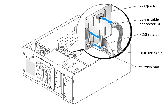
- Secure the backplane with the thumbscrew. See Figure 7-13.
Figure 7-13. Installing the SCSI Backplane Board
- Connect the power cable connector P3 to the power connector on the SCSI backplane. See
Figure 7-13.
- Connect the baseboard management controller (BMC) inter-IC (I2C) cable to the SCSI
backplane. See Figure 7-13.
- Connect the other end of the BMC I2C cable to connector BP_I2C on the system board. See
Figure A-3.
- Install the SCSI controller card.
See "Installing an Expansion Card" in "Installing System Components" for instructions about installing the card.
- Connect the SCSI data cable to the SCSI controller card, and to the SCSI interface
connector on the backplane. See Figure 7-12 and Figure 7-13.
- Install the cover. See "Replacing the Cover" in "Troubleshooting Your System."
- Stand the system upright.
- Install the SCSI drives into the hard-drive bay.
See Figure 7-11.
- Install the bezel. See "Installing the Bezel" in "Troubleshooting Your System."
- Reconnect the system to its electrical outlet and turn the system on, including any attached
peripherals.
- Install any required SCSI device drivers.
- Run the SCSI controllers tests and the hard-drive tests in the system diagnostics. See
"Running the System Diagnostics."
Installing a RAID Controller Card
See "Installing an Expansion Card" in "Installing System Components" for instructions about installing the card.
Back to Contents Page